October 31, 2014
Thesis
Ad-Hoc Context-Driven Changes in a
Busi-ness Process Management System
Wietse Smid
Faculty of Electrical Engineering, Mathematics and Computer Science (EEMCS) Software Engineering
Supervision:
University of Twente:
Dr. Lu´ıs Ferreira Pires
Dr. Eduardo Gonc¸alves da Silva
Capgemini:
Arjan Nieuwenhuis, MSc
A thesis submitted in partial fulfillment for the degree of Master of Science
ABSTRACT
Business Process Management Systems are used to keep track of business processes and the par-ticipation of (among others) employees in them. At the same time, smartphones are more prevalent in our daily lives than ever, bringing with them lots of knowledge about their context.
This available contextual information can be used to automatically change business processes to suit the context of their users better. To achieve this, ad-hoc changes to a business process can be defined in terms of change primitives and adaptation patterns. These changes are enacted through decisions made by a complex event processor, based on the contextual information sent by the em-ployee’s devices.
We design a software architecture that allows for these ad-hoc changes to be applied to the process instances in a Business Process Management System. We then use this architecture to develop a proof of concept implementation, and wevalidate this proof of concept through the application of typical examples of ad-hoc changes.
To improve is to change;
to be perfect is to change often.
PREFACE
As early as I can remember I always liked to solve puzzles. When I was young it would be jigsaw puzzles or building with LEGO, but as I grew older more complex puzzles took my interests, such as chess, illusions and computer games (although some knowledge of these might have been lost to time and/or beer). This combined with the fact that I was good at the exact sciences in school lead to me choosing, unsurprisingly, to study Computer Science at the University of Twente. During my bachelor I grew an interest in solving larger and more abstract puzzles, getting involved into software architecture. This in turn lead to the, again unsurprising, choice to do a masters in software engineering.
This thesis is the result of eight months of work at the University of Twente and Capgemini. After looking for a research topic for a while it dawned on me that I had no real pressing issues that I wanted to research myself. With the help of the folks at Capgemini I stumbled onto the idea of making busi-ness processes less rigid. I had worked with busibusi-ness processes and busibusi-ness process management systems before at my part time jobs, and noticed that improvements could be made. Using contextual information in mobile devices was not my first idea, but when I heard the idea it made sense to me, and I started my research. Eight months later, the result is this thesis.
I would like to thank my supervisors for their support in my research. Lu´ıs, who’s office door I could always barge in, announced beforehand of course, for helping me at the start, putting me on the right path. For always making me think and answer the questions that I had asked him myself only moments before, and for his fast replies in reviewing sections of my thesis, again with lots of”Think about what you really want to say here”-type comments written in the margins, which were always helpful.
I would also like to thank Arjan, for keeping me on track and reminding me that research can also have a value for the industry, not just academics. Discussions with him, specifically in the latter stages when I moved to Utrecht, were always of value and made me look at problems from different angles. I would also like to thank Eduardo, who may have only be involved in the later stages of the game, but provided invaluable feedback from even more different angles.
Besides my daily supervision there are other people that made this thesis possible. My girlfriend Nienke, whom I could always trust to kick my ass whenever I wasn’t working when I should have been. My father Nico, who may not be a computer scientist but is a doctor, for his trove of knowledge of academia in general, and academic English specifically. I could always call and ask for his advice. Christoph Bockisch, for being my track mentor during my masters and helping me with the formalities of writing a masters thesis. And last but not least Paul Sijbers, who was my first point of contact at Capgemini in the early days, for putting his faith in me (multiple times) when standardized tests and unexpected planning issues failed me.
Contents
1 Introduction 3
1.1 Context in Mobile Devices . . . 3
1.2 Business Process Management . . . 4
1.3 Synergies . . . 4
1.4 Goal . . . 5
1.4.1 Research Question and Objectives . . . 5
1.5 Report Structure . . . 5
2 Background Information 7 2.1 Context-Awareness . . . 7
2.1.1 What is Context? . . . 7
2.1.2 Context Types . . . 8
2.1.3 Defining Context-Awareness . . . 10
2.2 Contextual Information in Mobile Devices . . . 12
2.2.1 Sources . . . 12
2.2.2 Collection . . . 14
2.3 Complex Event Processing . . . 14
2.3.1 Event Processing Language . . . 15
2.3.2 Stream Processors . . . 16
2.4 Business Process Management . . . 17
2.4.1 Business Process Management Life-cycle . . . 17
2.4.2 Business Process Modeling Notation . . . 18
2.4.3 Business Process Management System . . . 21
2.5 Contextual Information in a BPMS . . . 21
2.6 Conclusion . . . 22
3 A BPMS for Ad-hoc changes 25 3.1 Ad-hoc changes . . . 25
3.1.1 Structure . . . 25
3.1.2 Constraints . . . 26
3.2 BPMS Components . . . 29
3.3 High-level Architecture . . . 34
3.4 Examples . . . 34
3.5 Conclusion . . . 37
4 AdHoc BPMS 39 4.1 Scope . . . 39
4.2 System Requirements . . . 40
4.2.1 BPMS Requirements . . . 40
4.2.2 Ad-hoc BPMS Requirements . . . 41
4.3 Use Cases . . . 42
4.3.1 U1: System Startup . . . 42
4.3.2 U2: Starting a Process Instance . . . 42
4.3.3 U3: Logging In . . . 43
4.3.4 U4: Task Completion . . . 43
4.3.5 U5: Context Information Update . . . 44
4.3.7 Relating Requirements and Use Cases . . . 45
4.4 Software Architecture . . . 45
4.5 Implementation . . . 46
4.5.1 Mobile Application . . . 46
4.5.2 Process Engine . . . 48
4.5.3 Stream Processor . . . 50
4.6 Conclusion . . . 53
5 Validation 55 5.1 Example Changes . . . 55
5.1.1 Removing a Node . . . 55
5.1.2 Adding a Node . . . 57
5.1.3 Exclusion of two Nodes . . . 58
5.1.4 Adaptation Pattern (Swap) . . . 59
5.2 Limitations . . . 61
5.3 Conclusion . . . 63
6 Conclusions 65 6.1 Results . . . 65
6.2 Future Work . . . 66
Chapter 1
Introduction
In this chapter we introduce the concepts of Context in Mobile Devices and Business Process Manage-ment, and we show the possibilities for synergy between them. We then define our research goal with accompanying research question and objectives. Finally a structure for the remainder of the report is given.
1.1
Context in Mobile Devices
In today’s world more and more people have a smartphone. Smartphone penetration is expected to reach 1.75 billion in 2014, rising to 2.5 billion as soon as 2017 [1]. How we use our smartphones has been the subject of research for some time. It has been shown that the time we spend using our smartphones already exceeds the time we spend online on our desktop computers [2]. We use our smartphones when we are at work, to read and reply to email, to make calls, to take notes and to keep our schedule close and up-to-date. As a result, our smartphones have access to a lot of information, which can be used for lots of different applications.
When a device has knowledge about itself and its surroundings it can use this information to react to a situation, as well as adapt to it if necessary. This type of systems are normally calledContext-Aware Systems (CAS). A CAS can have knowledge of this type of information about their users, the devices
they run on, as well as their surroundings [3]. They can make decisions and take actions based on that information. Some examples of CAS’ are: an automatic sliding door (a very simple context-aware system) and a car with Lane-Assist technology that warns the driver when he is leaving a lane.
artificial intelligence may be utilized for the decision making. However, most often CAS react and adapt to their environment because of a change in that environment. When multiple changes occur in the environment simultaneously, one might infer that something larger is happening. For example, if the level of light detected is dropping, we would not directly be able to determine its cause, but combining this with the information that there is no more GPS signal could lead us to infer the possible cause, namely that we walked in-doors. A technology that can assist in these situations is calledComplex
Event Processing(CEP), namely by combining multiple sources of information about a changing context
to reach decisions [4].
1.2
Business Process Management
Business Processescapture the way a company does its business, often as a combination of tasks and
transitions between tasks. Data may also be exchanged as a part of these transitions. The tasks in a business process then require only a transition to be chosen to reach the next task(s) [5]. To accurately keep track of these business processes they are defined in aBusiness Process Model. This exact defi-nition of a business process, together with a record of its executions, allows for analysis and comparison.
Companies are constantly trying to optimize their business processes with respect to various factors.
InBusiness Process Management (BPM), the business processes that a company uses can be
main-tained in aBusiness Process Management System (BPMS) [6]. A BPMS keeps track of the business processes and all the relevant factors, such as progression through the process and documents asso-ciated to a business process, throughout time. A BPMS also supports analytical methods that use this information to allow iterative improvement of business processes in theBusiness Process Management Life Cycle.
1.3
Synergies
The fact that we use our smartphones increasingly often in our daily lives opens up increasing possibili-ties to make use of this contextual information they have access to. Combining contextual information in mobile devices with complex event processing allows one to infer situations and take decisions based on the context captured by these devices.
that are temporary, or some that might be needed directly, can thus be realized without having to go through the iterative process. These changes can be done in an ad-hoc manner to allow the BPMS to change processes instances directly based on current contextual information.
1.4
Goal
The goal of this research is:To identify and demonstrate the benefits of combining Context-Awareness in Mobile Devices with Business Process Management, and design an architecture that can use these
benefits to apply ad-hoc changes to Business Processes.
1.4.1
Research Question and Objectives
To help achieve the goal of this research we have set out a research question and two research objec-tives:
RQ: What is the state of the art in the fields of Context-Awareness in mobile devices and Business Process Management, and how can they be combined?
RO1: Design a software architecture for a BPMS that can use these benefits to apply ad-hoc
changes.
RO2: Implement a Proof of Concept and validate the developed architecture.
To answer the research question we have performed a literature study of the relevant fields leading to a conclusion how they can be combined. The first objective asks for the design of a software archi-tecture, the answer to the research question will allow us to develop this architecture. For the second objective, we used the designed architecture to implement a proof of concept, with which we can vali-date the architecture.
The primary goal of this research is then achieved through the design and evaluation of an archi-tecture for a BPMS that supports the application of ad-hoc changes driven by contextual information from user mobile devices. To show the viability of such an architecture we have built a simple proof-of-concept.
1.5
Report Structure
Chapter 2
Background Information
This chapter gives the necessary background information for our research. We discuss the concept of context-awareness, contextual information in mobile devices, complex event processing and business process management. We conclude this chapter with a discussion on how these areas of research have been combined, and can be combined in the future.
2.1
Context-Awareness
When using the termContext-Aware Systems (CAS), the meaning of the word Context should be de-fined. This section investigates how most authors define Context, which kinds of context exist in Infor-mation and Communication Technology (ICT) and how such contextual inforInfor-mation can be represented in a computer system. We then discuss our definition of the term Context-Awareness and how context-aware systems make use of sensors to build a representation of their context.
2.1.1
What is Context?
In ICT, context plays an important role in case devices are designed to make autonomous decisions, because such autonomous decisions are often based on the context of the device. Several definitions of context exist. Schilit [3] defines context as:location, nearby people, hosts and devices, and changes to those things over time. Thus, context is all about the information that is relevant to the application.
Because context is can be complex, real world context is always transformed into a digital repre-sentation. This representation might be only accurate to a specified degree, and such partial accuracy might even result in the representation of the context being fundamentally different from the actual con-text [8]. When talking about concon-text we thus always have to take into account that the device is dealing with a constructed representation or model of the context and not the actual context. Furthermore, this representation is tailored to the application it is used for, and other contextual information irrelevant to the application is normally not considered.
2.1.2
Context Types
The concept of Context may be taken in a very broad sense. While the location of a device is relevant for many applications in terms of contextual information, some other forms of context might not be as easy to recognize. The categories given by Schilit and Ryan as listed in the last section can be extended. Dey et al. [9] divide context into 4 different categories: location, identity, activity, and time. These categories loosely correlate with other categorizations reported in similar research, such as physical, user, computing and time [10]. Below we discuss these four categories defined by Dey et al.
Location Context: The location of device can be important information for decision making. Knowing where a device is allows us to decide what can be done there. Furthermore, the location allows us to infer information about the physical things around us. By knowing which room we are in, we can infer what other items are present, all of which might influence our behavior. A location might be familiar to us or not, and different locations may elicit different responses.
Identity Context: Who we are, and what is around us can also be a part of context. Knowing that there are books on the table is often not enough, we might also want to know which books they are and maybe even who owns them. There are important differences between specific instances of objects. If we see our own cup of coffee on the table, picking it up and taking a sip is an option, but when it is not our cup our reaction might be different. We also want to react differently to different actors, and whether we know someone personally or not will affect our interactions too. Objects thus have an identity and are not by definition necessarily humans. Furthermore, more than one identity can be associated with an object, and we assume that each object has at least one identity associated with it.
de-pending on what some other actor is doing. The difference between speeding up or slowing down while driving a car towards someone is quite important when trying to decide which action has to be taken in order to avoid a collision.
Another example can be seen in smartphones, where multiple programs can be run at the same time. The fact that other programs are running can be important contextual information. For example, when a call comes in and the music player is running, an action can be taken to pause or mute the music player and let the call come through.
Temporal Context: Some things happen at predetermined times. A meeting, for example, might be scheduled from 1:00 pm to 2:30 pm. It is therefore important to know what the current time is if we want to make decisions based on things relative to time. This is most likely the local time, UTC or some other coordinated timeframe. A system that records lectures should only be active while a lecture is being given. This can be derived from the lecture time schedule, and the knowledge of the current timeframe relative to that schedule. Another example of temporal context being used, is when the automatic doors to an office only open during working hours.
Primary and Secondary Context
The context types discussed in this section can be mapped, respectively, to the questions Where?,
Who?, What?andWhen?. We call these types of context information primary context [9]. This
contex-tual information is retrieved through context sources; which are sub-systems that give access to context information. We can precisely define any context as a combination of these primary contexts. Further-more, if we have a central system where information is stored, then we can use these primary contexts as anchor points to retrieve more information, and we can infer secondary context from known primary context [9]. This secondary context entails other information related to primary context, for example, the e-mail address and job related to an identity. We can also infer primary contextual information about other entities. For example, by knowing the location of a device we can infer the other identities of other entities (people or objects) known to be in the same location.
Contextual Representation
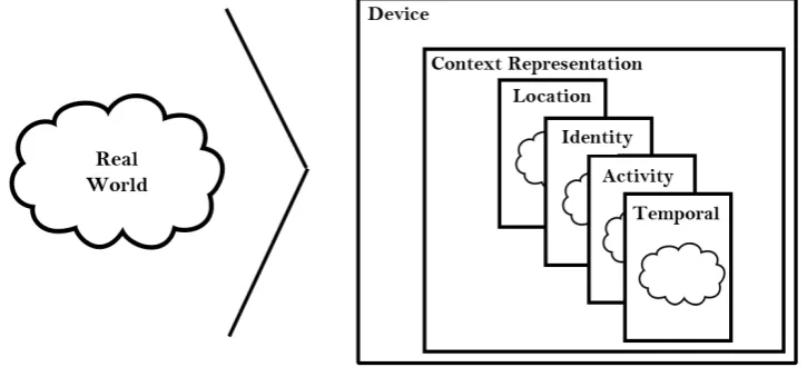
[image:19.595.105.468.278.452.2]Reasoning about context with computers presupposes a digital representation. This representation is only a model or an approximation of reality for two reasons. In the first place, our sensors have limited capabilities, such as speed and accuracy. This introduces a difference between the actual context and its representation. Secondly, it would not be feasible to build a completely accurate representation of the world, since there is simply too much information. We thus restrict ourselves to the information that is relevant to the application. This means that any reasoning about a contextual representation by necessity has to take into account that this information may be both incomplete and inaccurate. Figure 2.1 shows the duality between the real world, and the internal contextual representation.
Figure 2.1: A device with the real observable world and its internal representation
2.1.3
Defining Context-Awareness
Schilit et al. [3] defined Context-Aware Systems as systems that adapt according to their context. A lot of different definitions of context-awareness have been given by various authors. Dey et.al. discuss the various definitions of context [9], first defining the difference between using context and adapting to context. When using context, various inputs are used (human, sensory) to gain information about the context, and this information is then used as input for the application. In adaptation, the contextual information is used to perform actions that change the state of the application, such as changing the graphical interface of a program or opening an automatic door.
Dey et al. define context-awareness as follows:
A system is context-aware if it uses context to provide relevant information and/or services
This definition stresses the importance of the duality of using context and adapting to it: when pro-viding information, a system only utilizes the context, and when propro-viding services, a system performs actions based on the context. Furthermore, the definition stresses the relevance of the context to the task at hand. A context-aware system thus reacts and adapts to the context in a way that is useful to the user, and therefore being aware of context that is irrelevant to the task at hand does not comply with our definition of context-awareness. The relevance of a piece of contextual information, however, might change during operation.
Sensor Types
To obtain information about the context a system needs sensors, since sensors allow measurements of some form to be done about the context. Each type of context maps to one or more different types of sensors [11]. In this view, sensors are not restricted to hardware devices like microphones, but they can also be some software or even a service, such as, for example, a database of all postal codes and geographical locations.
For thelocation context, the most popular sensor is GPS, which allows location tracking with an ac-curacy of up to 5 meters [12]. Other techniques augment and improve GPS and increase its acac-curacy. Example of this augmentation are WLAN-based location that uses nearby WLAN access points with known location as references, as well as cell tower based location that uses the cellular network towers. Most of these techniques are less effective indoors because of physical barriers that block radio signals. Different techniques can then be used to infer the user’s position, such as an accelerometer to count steps and an internal compass to determine orientation, as well as specifically placed base stations to allow triangulation.
To establish theidentity context and find the identity of different objects, we can also rely on several sensors. In most wireless communications, identity is established by each communicating party. This is true for Bluetooth and WLAN, and to some extent also for RFID. One can also use the camera to determine object identities indirectly, possibly with the use of QR-codes [12]. Identification via audio, such as voice recognition, can also be used to determine if a specific person is nearby to some location.
Theactivity context defines what changes are happening and what is being done at the moment,
The system clock is the basic mechanism concerning thetemporal context. Through synchronization via the cellular network we can know the current time with reasonable accuracy. To know the relative times of different context changes, offsets to a fixed time, called timestamps, can be used. Timestamps identify the point in time that a change in context has occurred or will occur. This allows us to reason about these changes afterwards, and also to anticipate on changes in the future.
2.2
Contextual Information in Mobile Devices
Context-aware computing applications have been in use for a long time. Most of the existing applica-tions center around the use of ubiquitous sensing, where a large array of devices and sensors work together to gain information about the context of a situation and whereupon another set of devices and actuators act accordingly [3][13]. These networks of sensors normally have a fixed location, but might spread over a larger geographical area, allowing for a context-aware system to cover, for example, an entire building. An example is an indoor navigation system comprised of stationary displays and user
Radio-Frequency Identification(RFID) cards [14].
Another idea is to use the contextual information that is available on mobile devices to implement context-aware systems [11]. Although the reach of a distributed sensor network is not attainable with a single mobile device, other information sources are available. A mobile device can provide a wealth of contextual information that allows context-aware systems to adapt to the situation. For example, from the changing location (location context), a music player and aGlobal Positioning System(GPS) tracker being active (both activity context), a context-aware system may infer that the user is jogging or running. This information can then be used to adapt the system, for example by not allowing phone calls to go through, with perhaps the exception of some predefined phone numbers. This section discusses which concrete information, that may be acquired by mobile devices, is useful for decision making.
2.2.1
Sources
To consider the kind of information available to a mobile device we first discuss what sources are avail-able on a mobile device such as a smartphone. We refer to the sensor types from Section 2.1.
Applications
1. Calendar application Our schedule largely dictates our working life. Where we are, and with whom we are engaging in activities can provide us information about our availability.
2. Time sheet application When the hours that are spent working are logged in a time sheet applica-tion, information about spent time and available time can be inferred. This allows decisions to be made in terms of planning and preventing overtime working.
3. Employee information application When a company has an application that keeps track of all its employees’ information, then this information can be obtained. Simple things like their place of residence, but also more complex and secondary contextual information such as qualifications or temporary certifications can be obtained.
All these applications expose information. Calendar applications provide activity context, temporal context and maybe even locational context, for example, where a meeting is held. Time sheet and em-ployee applications provide identity and temporal context, telling us more about the emem-ployee himself, in terms of availability and capabilities.
Because the software on a mobile device can be as diverse as any software, there are endless possibilities for context information to be accessed by a mobile device, even more so with internet connectivity. To give a more specific example: any information about the person is contextual identity information. Theoretically, an application could do an automated web search for this kind of information. This shows that there are different levels of accessibility when it comes to contextual information, and care must be taken to specify the relevance of different sources of contextual information.
Locational
1. GPS: The Global Positioning System can provide a position almost anywhere on earth.
2. Wi-Fi: When locations of wireless networks are known a location can be determined based on which wireless networks are in range.
3. RFID: Using RFID and fixed receiver beacons we can derive a location for the device.
Other Sensors
Other sensors exist on a mobile device: camera’s, temperature sensors, microphones and more. How-ever, all these have limited effect on a business process, although examples can be thought of. For example, a temperature sensor can alter a business process to check for frozen railway switches more often. But such precisely localized temperature information is seldom required for business processes. Thus, while such sensors can in fact be used, their effective uses are limited.
2.2.2
Collection
The contextual information that all these sources generate, has to be aggregated to be useful for de-cision making. A separate piece of software is needed to retrieve all the relevant information, and to make it available for use.
There are two major ways to structure the retrieval of this information: polling and events, although a combination is also possible [15]. With polling, sensors are queried periodically for information, time be-tween information points is fixed, but the value might not change. With events, sensors report changes when they occur, timing differs, but there is always a change in value reported.
We argue that the simplest way is also the most effective: every change in value of some contextual information source should correspond to an event-notification. Because a small change might be of no informational value in continuous sensors, for example, the changing of the GPS position by 1 meter, we can define limits within which sensor values can fluctuate without triggering a change notification event. Simpler and discrete sensors, such as a calendar application, already have their own discrete events and those can therefore be collected. These streams of events can then be used in context-aware applications.
2.3
Complex Event Processing
the pitfalls associated with an approximation.
This section discusses how the information in event streams can be queried via Event Processing Languages (EPLs), and what their properties are. It further discusses how a stream processor uses event streams and queries in an EPL to automatically reach a decision about those event streams.
2.3.1
Event Processing Language
To understand and manipulate event streams, an Event Processing Language (EPL) is often used [16]. Such a language defines how events are described, and how they should be processed. Several of such languages exist, and examples are the SASE language that is specifically designed to analyze real-time streams of RFID readings [16] as well as the EP-SPARQL that combines on-the-fly analysis of streams with background knowledge and reasoning [17].
EPLs define rules according to the Event-Condition-Action (ECA) paradigm: ”on Event when
Con-dition do Action” [18]. These rules describe on which events and under what conditions an action has
to be taken. This type of rule can be extended with extra attributes, such as the time, a post condition or some complex term that can be evaluated or executed at a later time. In Listing 2.1 an ECA rule is given in the syntax of Paschke et. al. that describes that every 10 seconds a check is done to determine whether a service is requested by a customer. If this request is detected, then a server is searched, and if the server is found, the service is loaded. No particular post condition is given, and the notification op-eration here is enacted if the server cannot be found, in which case a message is sent to the customer [18].
eca (
every10Sec ( ) , % t i m e d e t e c t ( r e q u e s t ( Customer , S e r v i c e ) , T ) , % eve nt f i n d ( S e r v e r ) , % c o n d i t i o n l o a d ( Server , S e r v i c e ) , % a c t i o n ! , % p o s t c o n d i t i o n n o t i f y ( Customer , ” S e r v i c e r e q u e s t t e m p o r a r i l y r e j e c t e d ” ) . % complex term
}.
Listing 2.1: an ECA-type rule showing a service availability check
and SASE a form of query language is used to match events, albeit with some differences [16][17].
EP-SPARQL and SASE both use selectors to retrieve certain information from a matched event, event clauses to describe which events are to be matched, and condition clauses to filter events based on certain conditions. The event clauses enable the matching of sequential events, conjunction, disjunc-tion or absence of events, and concepts such as nonoccurrence of events between two other events. SASE also has an explicit construct to filter for time ranges.
In Listing 2.2 a simple example of a SASE rule definition is given that checks if the patient ’John’ has taken an overdose of antibiotics in the last four hours, by matching two MEDICINE-TAKEN events in se-quence and applying filters to check if the situation has occurred [16]. SASE was specifically designed to match events on real-time event streams. The action is therefore not defined in the SASE language itself but is left as an external construct [16].
EVENT SEQ( MEDICINE−TAKEN x , MEDICINE−TAKEN y ) WHERE [ name= ’ John ’ ] ∧ [ medicine = ’ A n t i b i o t i c s ’ ] ∧
( x . amount + y . amount ) > 1000 WITHIN 4 hours
Listing 2.2: a SASE rule checking for a medicine overdose of a certain patient
2.3.2
Stream Processors
A Stream Processor is a component that processes event streams. It takes event streams as input, together with rule definitions in an EPL, and then enacts the rules defined on the input streams. De-pending on the EPL, the decisions can be defined in the rules themselves or can be given in another format to allow separation of event matching and decision making. [16][17].
Figure 2.2: Interactions of a Stream Processor
2.4
Business Process Management
Many companies try to improve their business processes by using Information Technology. Business
Process Management (BPM) is an area that studies a company’s internal business processes. These
are identified and represented in process descriptions, and subsequently managed and optimized in a continuous monitoring and reviewing cycle [6]. Business Process Management states that business processes are characterized by a number of activities that are performed by computing systems, hu-mans, or their collaboration [19].
In this section we discuss how these business processes are continuously improved through the BPM life-cycle as well as show ways of representing and managing business process models.
2.4.1
Business Process Management Life-cycle
The BPM life-cycle is used to govern the process of designing, enacting, managing and analyzing of operational business processes. The phases of the BPM life-cycle might overlap, but are sequential, and the whole process is iterative [20]. The four BPM life-cycle phases are:
1. Process Design In this phase a model of either a current process or a desired process is produced. To be able to model all aspects of a process, this model can have several different perspectives, such as control-flow, data-flow, organizational and operational perspectives. In this part of the life-cycle, the model is changed according to knowledge about how the process works in practice.
can keep track of the execution of that model. Models are often constructed in an editor, as a result they can often be used as input to automatically create such a system configuration.
3. Process Enactment During this phase, the created system is actually used to manage the instances of the process model. Users can connect and interact with the system to complete tasks from the process model and advance it. Information about the executed process instances is stored in the system for later use.
4. Diagnosis The information gained during the enactment phase is analyzed in this phase. Here it may be decided whether the process model needs to be changed, based on the information about the executed process instances stored in the system. This phase therefore leads to a new Process Design phase, and the cycle starts over again.
[image:27.595.193.402.369.533.2]Through the Business Process Management life-cycle business processes can be continuously im-proved. The iterative nature of this life-cycle can be seen in Figure 2.3.
Figure 2.3: The BPM Lifecycle by van der Aalst [20]
2.4.2
Business Process Modeling Notation
of business process models, up to technical designs for developers who implement the business pro-cesses.
A BPD consists of several elements, connections and constructs [21]. The BPMN elements are discussed below.
Flow Objects There are three types of flow objects in BPMN:
1. Event An event is represented by a circle and means that something happens. They usually have a cause (trigger) or an impact (result). Events are split into three types: start events, intermediate events and end events.
2. Activity There are two types of activities: task and sub-process. Activities represent the work performed by a company and is shown as a rounded rectangle. A task is a single atomic activity and a sub-process can contain multiple activities, events and gateways connected through flow objects.
3. Gateway A gateway is shown as a diamond and can control the sequence flow through deci-sions, forking, merging and joining of paths.
Connecting Objects The three types of flow objects are connected via three possible connecting ob-jects:
1. Sequence Flow A sequence flow shows which activity is to be performed next, it thus defines the order in which activities occur in a process. It is represented as a solid line with a solid arrowhead.
2. Message Flow The flow of a message between two participants is shown as a dashed line with an open arrowhead. Participants are separate business entities or business roles, and are represented by two separate pools (Swim lanes).
3. Association An association is shown as a dotted line with an open arrowhead. It is used to associate data, text and other artifacts with flow objects.
Swim lanes With swim lanes we can visualize activities together as a region. BPMN has two types of swim lanes:
2. Lane A pool can be subdivided in lanes. Lanes are used to categorize and organize activities. Lanes have their own names.
Artifacts Besides the functional elements, BPMN has a few artifacts that offer the option of annotating the BPD without changing the process it represents. Artifacts can be added to a BPD to pro-vide extra information about the business process that is modeled. BPMN defines the following Artifacts:
1. Data Object Data objects are connected to activities via associations. They represent the data that is required or produced by an activity.
2. Group A group is shown as a rectangle with a dashed border. It can be added for documenta-tion or analysis purposes, but it does not affect the Sequence Flow.
3. Annotation Annotations allow textual comments to be added to the BPD.
[image:29.595.77.524.467.728.2]Figure 2.4 shows an example of a BPD in BPMN for the customer request of a new account for a service. It shows the swimlanes indicating different users, as well as the general processing of the request through events (circles), actions (squares) and gateways (diamonds). They are connected through sequence flows (solid arrows), message flows (dashed arrows) and data flows (dotted arrows). The pool has its own start and end events which are accompanied by message flows with the customer.
2.4.3
Business Process Management System
A Business Process Management System (BPMS) supports the entire BPM life-cycle. A BPMS consists of several software components that support modeling, configuration, enactment and analysis of Busi-ness Processes. A BPMS delivers a consistent process management experience, enabling busiBusi-ness managers to monitor, analyze and refine the execution of a company’s business processes [23].
A Business Process Management System typically consists of the following components:
1. Process Modeling Tools The process modeling tools support the creation and modification of BPD’s that can then be executed by the process engine.
2. Process Engine The process engine allows for the execution of business processes and keeps track of all the running process instances.
3. Business Analytics The business analytics component gives insight to managers about completed and running business process instances. It can show problems, trends and opportunities through reports and dashboards.
4. Content Management The content management system stores electronic documents, images and files relevant to the business processes.
5. Collaboration Tools The collaboration tools allow employees to communicate and collaborate with each other.
2.5
Contextual Information in a BPMS
Some research has been done into using contextual information in a BPMS, and several approaches to the concept have been taken. In this section, we discuss illustrative parts of this research and show the breadth of possibilities for using contextual information in a BPMS.
In broadly defined business processes, multiple routes can be taken from start event to end event. Van der Aalst [24] uses contextual information to navigate through such a business process, feeding the information to a path finding algorithm found in car navigation software as a means to steer the business process execution. Most of the contextual information used is retrieved from event logs of previous executions.
decision. Rather than only using information available in the process, contextual information can be taken into account as well in that decision. Reseman et. al. [25] give an example of an airline check-in process. Multiple routes through the process are defined and a decision to take a specific route is based upon contextual information, such as the availability of an internet connection.
Another approach is to extend the BPMN specification with contextualized elements. These mobility events are designed to be triggered upon the reaching of a position by a participant, possibly supple-mented by an additional condition. This allows for business processes to be sensitive to the contextual location data of its participants [26].
In the research done by Santos et. al. [27] contextual information is gathered during the execution of a process. This information is recorded together with an instance. Using Non-Functional Requirements (NFRs) that define quality and constraints, the authors describe the desired goal of a business process. They then develop a framework where using these NFRs, possible variations in a business process are computed based on contextual information. These variations are then applied to the process model, and new instances be started with these variations on the business process model.
The concept discussed in the research by Santos et. al. [27] can be expanded. The mobile devices of end users of a BPMS have access to contextual information. With this contextual information, we can change the business processes not just automatically every iteration of the business process manage-ment life-cycle, but all the time, and ad-hoc. These ad-hoc change have to be defined in advance, but which actual changes are applied is decided at runtime based on contextual information.
2.6
Conclusion
In this chapter, we discussed what context is, and how it can be viewed as a layered system that can have digital representation. We discussed how devices are aware of their context through sensors, and how context can be viewed with regards to mobile devices. We then discussed how we can use multiple sources of contextual information to make decisions based on patterns.
Chapter 3
A BPMS for Ad-hoc changes
Business Process Management Systems have been around since the early 2000’s, and they have evolved to a point where the basic architecture is generally agreed upon [28]. In this chapter we discuss a technique to represent and apply ad-hoc changes on process instances. We investigate how the current BPMS architecture can be adapted to accommodate for a BPMS in which contextual information can be used to support ad-hoc changes on a process model or a process instance. Finally we present some examples to show the applicability of a BPMS that supports ad-hoc changes.
3.1
Ad-hoc changes
To design an architecture for a BPMS that supports hoc changes we first have to define what ad-hoc changes exactly are and how we can structure and use them. We discuss what types of ad-ad-hoc changes can be applied to a process model and how these changes can be combined and structured. Because we want to prevent changes that might eventually result in unexpected errors, we look at the problems that might arise when changing a process model. We discuss the concepts of soundness, state compliance and dynamic change correctness, and how they can be used to determine which ad-hoc changes can be applied and which cannot.
3.1.1
Structure
Change Primitives
We can effectively change a process model by adding or removing any element of this process model: activities, connections, gateways etc. Because a process model can be viewed as a directed graph, and each element is either a node or an edge, we restrict ourselves semantically to the following Change Primitives:add node,remove node,add edgeandremove edge.
Adaptation Patterns
Because single Change Primitives carry little semantic meaning we use a method to combine them into high-level change operations, such as the insertion, deletion or manipulation of an entire process fragment. We use the termprocess fragmentto describe a connected component of the process graph with a single input and output. High-level changes are thus effectively structured as a series of Change Primitives. Figure 3.1 shows the high-level change operation of parallelizing two sequential activities by adding two gateways. The individual change primitives that were applied to achieve this change are:
Remove Edge Start - Activity A
Remove Edge Activity A - Activity B
Add Node Parallel Gateway (id:par-gate-1)
Add Edge Start - par-gate-1
Add Edge par-gate-1 - Activity A
Add Edge par-gate-1 - Activity B
Remove Edge Activity B - Activity C
Add Node Parallel Gateway (id:par-gate-2)
Add Edge Activity A - par-gate-2
Add Edge Activity B - par-gate-2
Add Edge par-gate-2 - Activity C
High-level changes such as adding a process fragment or removing one can be seen as the building blocks for ad-hoc changes. These recurring changes that can be described in an abstract way are called Adaptation Patterns. Table 3.1 lists the thirteen adaptation patterns for modifying a process model that Reichert and Weber [29] classified, in five categories.
3.1.2
Constraints
Figure 3.1: The high-level change operation to parallelize Activities A and B.
Pattern Category Pattern
Adding or deleting AP1: Insert Process Fragment Process Fragments AP2: Delete Process Fragment Moving or replacing AP3: Move Process Fragment Process Fragments AP4: Replace Process Fragment
AP5: Swap Process Fragment AP14: Copy Process Fragment Adding or removing AP6: Extract Subprocess
Process levels AP7: Inline Subprocess
Adapting control dependencies AP8: Embed Process Fragment in loop AP9: Parallelize Process Fragments
AP10: Embed Process Fragment in conditional branch AP11: Add control dependency
AP12: Remove control dependency Change transition condition AP13: Update condition
Table 3.1: Adaptation Patterns for Changes in Process Models [29].
dynamic change correctness. Together, these ensure that ad-hoc changes have no erroneous side-effects on the process instance and models. Ad-hoc changes shall only be applied when they preserve these properties.
Soundness
[image:36.595.69.490.326.501.2]State Compliance
The state of a process instance includes which activities have been completed, which are enabled, and which are running. Together they form the execution trace for a process instance. When applying an ad-hoc change, we have to make sure that the execution trace of the process instance is compatible with its model, since the record of how the process was executed cannot be modified. To enforce this immutability, we use the definition of State Compliance:
State Compliance”Let I be a process instance with execution traceσI. Further, let T be a process
model. Then, I is state-compliant with T ifσI is reproducible on T.”[29]
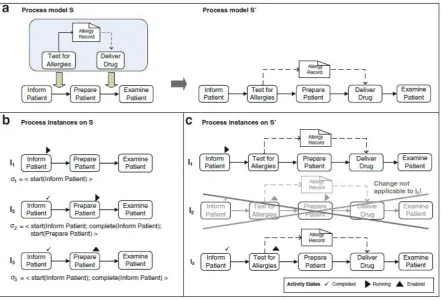
If we only apply ad-hoc changes that adhere to state compliance, then we can ensure that the his-tory of process instances is not changed. In Figure 3.2 we can see the process model of a treatment and its ad-hoc change. It can be seen that in I1 there is no problem as the execution trace can be
executed fine. InI2we see that the injection of the activity ”Test for Allergies” invalidates the execution
trace. Thus resulting in a process that is not state compliant, and therefore the ad-hoc change cannot be executed. Instance I3 has no problem recreating the execution trace and is thus state compliant.
However, the insertion of the ”Test for Allergies” activity means that the ”Prepare Patient” activity is no longer the next activity in line, and thus the collection of enabled activities needs to be changed.
Dynamic Change Correctness
If an ad-hoc change moves activities through a process instance, then we must take care to preserve the soundness of that process instance. In Figure 3.1, if we assume that Activity A was enabled, then after the change, Activity A will be enabled but Activity B will not, leading to a deadlock or a Dynamic Change Bug. Any ad-hoc change can only be applied if the resulting instance is a valid instance of the changed underlying process model. For example, an ad-hoc change cannot be applied to a process instance that has progressed too far, where applying the ad-hoc change would introduce a dynamic change bug. We give below the definition of Dynamic Change Correctness [29]:
Dynamic Change Correctness”Let I = (S,σI) be a process instance running on a sound process
model S and having execution traceσI. Assume further that S is transformed into another sound
process model S’ by applying changeδ, i.e.S[δ > S0. Then:
• δcan be correctly applied to I if I is state compliant with S’.
• Assume I is state compliant with S’. When applyingδto I, correct activity states of I on S’ can be
obtained by applying σI to S’; i.e., by logically replaying the events captured byσI on S’ in their
Figure 3.2: An image showing how an ad-hoc change is enacted or not because of state compliance and. [29]
Dynamic Change Correctness thus ensures that an ad-hoc change can only be executed if the result of that change is a valid state for the underlying changed process model. With these two notions we can make sure that ad-hoc changes will only take effect when they result in valid process instances, preventing run-time errors that disturb the operation of the BPMS.
3.2
BPMS Components
To incorporate the functionality of ad-hoc changes into a BPMS, we look at the different elements of a standard BPMS, and determine if they are affected by this change, and if so, how they are affected. Figure 3.3 shows the architecture of a standard BPMS. We then look at any additional elements that may be necessary to incorporate ad-hoc changes.
Process Modeling Tools
Figure 3.3: The architecture for a standard BPMS
at every point in the execution of a process instance, the BPD should be sound. What changes can happen and under which circumstances can be informed separately to the Process Engine.
In Figure 3.4 we see a screenshot of the Eclipse IDE plug-in from the Open-Source JBoss jBPM BPMS. The simple drag-and-drop interface provides an easy way to construct BPDs. It stores its BPDs as XML files according to the BPMN meta-model defined by the OMG [30]. The interface and standard-ized format suit our needs for a Process Modeling Tool. As a result, no changes are required in the Process Modeling Tool to function with ad-hoc changes.
[image:39.595.72.524.514.729.2]Process Engine
In a standard BPMS the Process Engine spawns new process instances from defined process models and keeps track of their execution. Participants can perform activities and the process advances. When the capability to apply ad-hoc changes on the process instances is added, a few extra requirements arise:
1. Defining Possible Changes To define possible changes we make use of an Event Processing
Language (EPL) as described in Section 2.3. This allows us to define a change and under what circum-stances this change needs to be applied. This is done via the Event-Condition-Action pattern. Listing 3.1 shows an example of an ECA definition of a change in pseudo code.
Therefore we need to add an interface to the Process Engine that executes these changes when called upon. These changes should be stored in a way that facilitates easy comparison and analysis. A suitable way to do this is to store them as incremental changes to the initial BPD.
2. Applying Ad-hoc Changes: To decide when to apply ad-hoc changes to a process instance, a
Stream Processor is added to the BPMS. This Stream Processor uses information streams and the change definitions described in the EPL to decide when a change should be applied. It then calls the Process Engine, which in turn can execute the changes on the relevant process instance(s).
Event :
Calendar ev ent has s t a r t e d C o n d i t i o n :
Employee A i s p r e s e n t a t t h e c a l e n d a r e ven t A c t i o n :
D i s a b l e t h e a c t i v i t y ” Meet w i t h Employee A ”
Listing 3.1: An example ECA rule
Furthermore we have to comply with the principles of soundness, state compliance and dynamic change correctness introduced in Section 3.1. The responsibility of applying ad-hoc changes only when these concepts are not violated lies with the process engine, which must reject any ad-hoc changes that do not comply with these principles.
Business Analytics
Business Analytics tooling. Different traces through process instances that have had the exact same ad-hoc changes applied, and thus have the exact same BPD graph, may still be analyzed as equal processes.
However, this might lead to problems when a business process is defined with many possible ad-hoc changes. As we increase the number ad-ad-hoc changes, the total number of possible unique BPDs resulting from these changes can grow exponentially with the number of ad-hoc changes. Having this many different unique types of BPDs can render the analytics useless, as even in a large organization there might not be enough process instances which a specific BPD to perform meaningful analyses.
There are, however, options for meaningful analyses even when two process instances do not have the same underlying BPD. In Figure 3.5,P1andP2are the result of two different ad-hoc changes
ap-plied toP. Since their BPDs are different, instances ofP1 are not comparable to instances ofP2, and
no analysis can be done. But if we look more closely, then we can see that the first parts of the BPDs of P1 andP2 are the same. As a result we can still perform some analysis on those parts of process
instances that have BPDs that are equal. This requires that the analytics tooling can infer which parts of two instances are equal.
Therefore, the analysis methods used by the Analysis Tools in a standard BPMS are viable for our BPMS with ad-hoc changes. However, more specific methods can be developed to provide even better analysis for process instances with differently changed BPDs.
Content Management System
The requirements for a Content Management System do not change for a BPMS with ad-hoc changes. Files and information are still stored for each process model and process instance when required. We assume that the identity of a process instance does not change, split or merge when executing an ad-hoc change, therefore, we do not require any extra functionality from the Content Management System.
Collaboration Tools
Figure 3.5: A Process P with two possible changed processes P1 and P2.
Stream Processor
A Stream Processor is necessary in a BPMS with the functionality to apply ad-hoc changes. In Section 2.3, we state that the Stream Processor receives streams of events generated by contextual changes. These streams can be supplied by the BPMS itself, but more useful information can be retrieved from other sources, such as the mobile devices of the participants. The Stream Processor uses a predefined EPL description to apply the defined ad-hoc changes to the process engine based on a stream of events.
Device Application
In a regular BPMS there are many ways for the users that are involved in a process to interact with the system. Normally, users interact with the BPMS through an application, which may be through a web interface or in a specially designed mobile application.
3.3
High-level Architecture
Our ad-hoc BPMS has been designed as an extension of a regular BPMS. Figure 3.6 shows that only a few extra components are necessary, and a few components have to be modified (in green), and that the architecture is fully backwards compatible with a regular BPMS (in black).
TheDevice Applicationis situated on the user mobile device. Current BPMS might even have such
an application with an integrated user interface. In our ad-hoc BPMS this application also aggregates and relays the contextual information. The device application can be opened at will to interact with the system and complete tasks. In the background, information is continuously gathered and sent to the system. The ad-hoc BPMS further adds aStream Processor that receives the information streams that
theDevice Applicationsends, and acts according to the given ad-hoc change specification.
The Process Engine is modified to allow for ad-hoc changes of process models and process
in-stances. TheAnalytics Softwareis extended to deal with modified process instances. Since both the
Process Engine andAnalytics Softwareonly add functionality to their regular counterparts, this
[image:43.595.183.413.411.589.2]archi-tecture is a proper extension of the regular BPMS.
Figure 3.6: A high-level architecture for an ad-hoc BPMS.
3.4
Examples
It is not a coincidence that these examples mainly involve the inclusion or exclusion of employees based on contextual information. Mobile devices are user-centric and thus have quite a lot of information about their users and their direct environments.
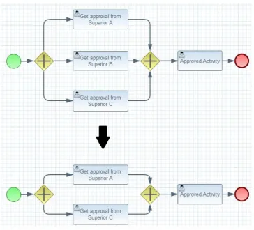
Office Availability
[image:44.595.116.481.320.650.2]In this example an employee has to get approval for some activity by any one of his three superiors. When his request is approved, the employee can continue and carry out that activity. In Figure 3.7 we can see this example where the employee has to get approval from Superior A, B or C. In this case, there might be an ad-hoc change description that describes the deletion of an activity if the relevant superior is not available at the moment. In the case of Figure 3.7, Superior B is unavailable, thus his option is removed from the process instance at runtime.
Figure 3.7: Ad-hoc change for the Office Availability example
Task Assignment
follow a training, allowing him to complete the activity. Figure 3.8 shows an example where we can see that the process instance is modified with an activity for the employee to follow training, after which the process is restored to its original state, and the original activity can be completed.
Figure 3.8: Ad-hoc change for the Task Assignment example
Meeting Location
If a meeting has to take place between two parties to sign a contract, then we could imagine a business process instructing both parties to meet and sign the contract. In the example of Figure 3.9, locational data has shown that both parties that are supposed to meet are far away from each other, and even though the actual signing still has to be done personally, the discussion about the contents of the con-tract might possibly be done via teleconference.
An ad-hoc change can be defined, that offers another separate option to scheduling a meeting and signing the contract. Figure 3.9 shows that an extra path is added by which instead of a meeting to discuss and sign the contract, the discussion is done via teleconferencing. The actual formality of signing is postponed to a later date as a separate action.
Emergency Response Volunteering
Figure 3.9: Ad-hoc change for the Meeting Location example
are called, the location may become too crowded to be effective, and if too few are called, insufficient manpower may be available to support the professional staff. Individual volunteers thus have to be called to the scene, and this can be done manually by phone or automatically via push messages.
Given a number of volunteers, we can construct a business process that requires them all to be called to the scene. We can then define an ad-hoc change that removes any ineligible volunteers based upon contextual information such as location, availability and training. Furthermore we can remove or add as many volunteers as we need to reach a desired number, possibly using margins to overcome unknown variables.
Figure 3.10 shows how such a business process would be transformed to reach the desired out-come. When five volunteers are on record and only 2 are needed, 3 can be eliminated from the process by any number of reasons. In this example, John might be ill, and Maggie and Mike are just not needed at the time.
3.5
Conclusion
Figure 3.10: Ad-hoc change for the Emergency Response Volunteering example
We further looked at the components of a regular BPMS and assessed how they would change when the ad-hoc changes functionality is added to the system. We showed that a regular BPMS can be ex-tended to support ad-hoc changes. Most notably the Process Engine requires an extension to deal with changing process models and instances. Furthermore, to drive these changes, the device application gathers contextual information and sends it to an additional component called Stream Processor. This Stream Processor executes the desired ad-hoc changes on the Process Engine. Finally an extension to the Analytics Engine can be made to improve the possible analysis of execution traces of changed process instances.
Chapter 4
AdHoc BPMS
To validate our approach and high-level architecture, a proof of concept was developed, which we called the AdHoc BPMS. In this chapter we detail the system requirements of the proof of concept implementation, show several use cases and present the architecture of the proof of concept. We show how the individual software components are designed and implemented, and give an example showing how the final system works. We conclude the chapter by presenting some limitations of the developed proof of concept, and argue why these limitations do not pose a problem when a full implementation is considered.
4.1
Scope
Because this proof of concept is developed to validate the concept and architecture of ad-hoc changes in a BPMS, we limit the scope of this proof of concept to those elements that are influenced by ad-hoc changes. Figure 4.1 shows the boundaries of this proof of concept in a blue dashed line.
Contained within this proof of concept are the core components necessary to facilitate the applica-tion of ad-hoc changes to process instances: the mobile applicaapplica-tion, the process engine and the stream processor. Each of these are discussed in more detail in this chapter.
Finally we leave the analytics engine out of the scope of this proof of concept. However, as the recorded information on business process instance execution is fundamentally the same as without ad-hoc changes, any standard business process analysis should be able to do the job. The only caveat is that the data generated by the process engine is delivered in a format that can be imported by the analysis tool of choice.
Figure 4.1: The scope of the proof of concept compared to the complete architecture.
4.2
System Requirements
To develop a proof of concept we first specify the system requirements. Because we are building an extension to a standard BPMS we start by specifying the system requirements for a standard BPMS. We then specify the extra requirements that are necessary to support the ad-hoc changes capabilities.
4.2.1
BPMS Requirements
Figure 4.1 shows the two existing components that we are going to extend in black, namely the process engine and the mobile application. We discuss the functionalities that these two components need to provide and from those we derive the system requirements.
pre-defined business processes. It does this by starting new instances, managing the activities that are possible at any one time, and allowing users to complete activities on instances. We thus come to the following system requirements:
R1: The process engine shall be able to import business processes designed by the
mod-eling tool.
R2: The process engine shall provide a way to start new process instances.
R3: The process engine shall provide an interface to expose actions on running process
instances.
R4: The process engine shall provide an interface to receive actions that are to be enacted
on running process instances.
R5: The process engine shall change the state of a process instance according to the
re-ceived actions.
TheMobile Applicationfunctions as the end user interface to the system. As such it provides a way
to log in to the system. Furthermore, to interact with the system we must be able to receive all activities that are relevant to the user that is logged in from the process engine, as well as being able to enact those activities and send those actions to the process engine. We thus come to the following system requirements:
R6: The mobile application shall provide a way for a user to log in to the system.
R7: The mobile application shall provide a way to retrieve all possible actions relevant to the
logged in user from the process engine, and present them in a graphical user interface.
R8: The mobile application shall provide a way for a user to take an action, and send it to
the process engine.
4.2.2
Ad-hoc BPMS Requirements
We next add the system requirements that are necessary to support context-driven ad-hoc changes. Figure 4.1 shows the components that are needed to do so in green. We therefore have to define extra system requirements for the process engine and the mobile application, and define system require-ments for the stream processor.
To be able to apply ad-hoc changes, the Process Engine needs to be able to change process instances.
The contextual information used to drive ad-hoc changes is collected in the Mobile Application. It needs to periodically collect the contextual information and send it to the stream processor. In this proof of concept we restrict ourselves to calendar and location information.
R10 The mobile application shall be able to aggregate contextual information and send it to
the stream processor.
The Stream Processor receives contextual information from the Mobile Applications of the BPMS
end users. It matches the contextual information to a predefined EPL specification, and sends the ad-hoc changes defined in the EPL to the process engine.
R11: The stream processor shall be able to import an EPL description.
R12: The stream processor shall be able to match incoming contextual information to
ad-hoc changes described in the EPL description.
R13: The stream processor shall be able to send ad-hoc changes to the process engine.
4.3
Use Cases
We define several use cases to further describe the functionality of the system. We loosely followed the format described by Fowler [33], namely: give a description for each use case, a number of steps that dictate the interaction between actors and the system, and a possible list of extension steps. We show a use case diagram, and relate use cases to the requirements specified in Section 4.2.1.
4.3.1
U1: System Startup
Description:At the startup of the system, BPMN and EPL specifications are supplied to the system. The
system starts up the process engine and the stream processor, and populates them with the BPMN and EPL specifications, respectively.
Steps:
1. Administrator User locates the BPMN and EPL files that are necessary for the BPMS.
2. Administrator User starts the system and provides the BPMN and EPL files.
4.3.2
U2: Starting a Process Instance
Description: When the system is started, an administrative user can use the back-end interface to start
Steps:
1. Administrator User opens the interface to the BPMS.
2. Administrator User starts a new instance of the desired process.
4.3.3
U3: Logging In
Description: When an end user starts the Mobile Application, he is prompted for his name, and the
location (IP address and port number) of the BPMS server. After entering the information and sending it to the server, the user is logged in.
Steps:
1. End User opens the Mobile Application.
2. End User enters his name, and the location of the BPMS Server.
3. End User connects to the Server and is logged in.
4.3.4
U4: Task Completion
Description: A logged in user can ask the process engine to list all available activities. He is first
prompted to select a process for which he wants to complete an activity. After choosing a process, all available activities for that process are shown. The user can then select an activity and send a completion request to the process engine. The process engine receives this request and modifies the corresponding process instance accordingly.
Steps:
1. End User opens the Mobile Application.
2. End User selects the desired process from the list.
3. End User confirms the selected process
4. End User selects the desired action from a list.
5. End User confirms the completion of the selected action.
Extension:

![Figure 2.3: The BPM Lifecycle by van der Aalst [20]](https://thumb-us.123doks.com/thumbv2/123dok_us/9896414.490931/27.595.193.402.369.533/figure-bpm-lifecycle-van-der-aalst.webp)
![Figure 2.4: Example of a Business Process Diagram in BPMN-notation [22]](https://thumb-us.123doks.com/thumbv2/123dok_us/9896414.490931/29.595.77.524.467.728/figure-example-business-process-diagram-bpmn-notation.webp)

![Figure 3.4: The jBPM Process Modeling Eclipse plug-in [32]](https://thumb-us.123doks.com/thumbv2/123dok_us/9896414.490931/39.595.183.413.68.249/figure-jbpm-process-modeling-eclipse-plug.webp)