http: //www.cascom.army.mil/ordnance/,
to submit your questions, comments, and suggestions
regarding Ordnance and Missile & Munitions
subcourse content.
If you have access to a computer with internet capability and can
receive e-mail, we recommend that you use this means to
communicate with our subject matter experts. Even if you’re not
able to receive e-mail, we encourage you to submit content
inquiries electronically. Simply include a commercial or DSN
phone number and/or address on the form provided. Also, be sure
Fundamentals of Electricity Course
BASIC ELECTRICITY
PART I
*SUBCOURSE MM0703
US Army Ordnance, Missile and Munitions Center and School
This publication is provided for nonresident instruction only. It reflects the current thought of this school and conforms to published Department of the Army doctrine as closely as possible.
MM 0703
CONTENTS
INTRODUCTION, vi
Supplementary Requirements, vi Credit Hours, vi
Administrative Instructions, vi
Grading and Certification Instructions, vii
LESSON 1: ELECTRON THEORY AND MAGNETISM (TASKS: ANY MISSILE REPAIRER TASK), 1 Electron Theory, 1
Basic Concepts of Matter, 1 Molecules, 1
Atoms, 2
Ions and Ionization, 3 Static Electricity, 3
Conductors and Insulators, 8
Distribution of Charges on Objects, 8 Electrostatic Shielding, 9
Magnetism, 9
History and Definition, 10 Forces Between Poles, 10 Magnetic Fields, 12
Terrestrial Magnetism, 14
Theory of Permanent Magnets, 15 Electromagnetism, 16
REVIEW EXERCISES, 22
LESSON 2: CIRCUITS (TASKS: ANY MISSILE REPAIRER TASK), 27 An Electric Circuit, 27
Terminology, 27 Kinds of Circuits, 28
Electrical Measurements, 28 Coulomb, 28
Ampere, 29
Ohm, 29
Volt, 29
Watt, 29
Electromotive Force, 29 Current, 30
Resistance, 30 Fixed, 30 Adjustable, 31 Variable, 31
Laws, 32 Ohm's Law, 32
Kirchoff's Laws, 34
Power, 38
Special-Case Problem Solving, 39 REVIEW EXERCISES, 44
LESSON 3: DIRECT AND ALTERNATING CURRENTS (TASKS: ANY MISSILE REPAIRER TASK), 49
Definition, 49
Direct Current, 49 Alternating Current, 49 History, 50
Generation of Current and Voltage by an AC System, 60 Principles, 50
Generation of AC Voltage, 52 Graphic Representation of AC, 55
Frequency of AC Voltage and Current Waves, 59 Angular Motion, 60
Amplitude, 61
Determining Amplitude, 61 Effective AC Voltage, 62
Phase, 63
MM 0703
LESSON 4: CAPACITANCE AND INDUCTANCE (TASKS: ANY MISSILE REPAIRER TASK), 72
Capacitance, 72
Measure of Capacitance, 73 Physical Characteristics, 74 Series Connection, 75
Parallel Connection, 76 Capacitive Reactance, 76
Phase Relationship in a Pure Capacitive Circuit, 80 Types of Capacitors, 80
Inductance, 84
Unit of Induction, 87
Phase Relationship in a Pure Inductance, 88 Inductive Reactance, 88
Series and Parallel Connection of Inductors, 90 Factors Determining Size of Inductance, 91 Series Resistive and Capacitive Circuits, 92 Power Dissipation in RC Circuits, 94
Effect of Frequency Change in RC Circuits, 96 Series Resistive and Inductive Circuits, 96 Power Dissipation in RL Circuits, 97
Effect of Frequency Change in RL Circuits, 98 REVIEW EXERCISES, 99
END-OF-SUBCOURSE EXAMINATION, 104 EXERCISE SOLUTIONS, 111
INTRODUCTION
This is the second of three subcourses on basic electricity. The first subcourse is a review of the mathematics necessary for the study of electricity. This subcourse includes the electron theory, magnetism, inductance, capacitance, and alternating and direct currents. The third subcourse includes resonance, filters, generators, motors, and transformers. As a missile repairer, an understanding of basic electricity is a must for doing your job. Whether you are new to missile repair or have been in the field for a while, this subcourse will help you sharpen your skills and increase your knowledge.
Supplementary Requirements
There are no supplementary requirements in material or personnel for this subcourse. You will need only this book and will work without supervision. Credit Hours
Fifteen credit hours will be awarded for the successful completion of this subcourse--a score of at least 75 on the end-of-subcourse examination.
Administrative Instructions
Change Sheets. If a change sheet has been sent to you with this subcourse, be sure you post the changes in the book before starting the subcourse.
Errors on TSC Form 59. Before you begin this subcourse, make sure that the information already typed on your TSC Form 59 (ACCP Examination Response Sheet) is correct. You will find the correct subcourse number and subcourse edition number on the front cover of this book. If any of the information on your TSC Form 59 is incorrect, write to:
The Army Institute for Professional Development (IPD) US Army Training Support Center
Newport News, VA 23628-0001
A new, correctly filled-out form will be sent to you. Do not correct the form yourself or send it to IPD.
Questions, Changes, Corrections. If you have questions about enrollment or other administrative matters, write to IPD. If a change occurs or a correction needs to be made in your status (name, grade, rank, address, unit of assignment, etc.) notify IPD as soon as possible. These kinds of changes or corrections can be sent along on a separate sheet of paper with your completed TSC Form 59.
MM 0703
Grading and Certification Instructions
When you have completed the subcourse, review any of the material covered that you are not sure of. Then take the end-of-subcourse examination. When you have completed the examination in the book, you must transfer your answers to TSC Form 59. The instructions on the form itself tell you how to mark your answers on it. Follow the instructions carefully.
Once you have transferred your answers to the TSC Form 59, fold the form as it was folded when sent to you. Do not staple or mutilate this form! Place the form in the self-addressed envelope provided and mail it to IPD. No postage is needed. TSC Form 59 is the only material that you are required to return to IPD. If you return it as soon as you have completed this subcourse, you will get your next subcourse sooner.
Grading. The highest score possible on the end-of-subcourse examination is 100. The grade structure for all ACCP subcourses is given below:
Superior 95-100 Excellent 85-94 Satisfactory 75-84 Unsatisfactory 0-74
Your TSC Form 59 will be machine graded, and you will be notified of the results. Your grade on the examination will be your grade for the subcourse. No credit is given for grades below satisfactory (75).
Certificates. When you have completed the subcourse successfully, IPD will send you a subcourse completion certificate. Keep it with your other personal copies of personnel material. Subcourse completion certificates can be used to support accreditation and other personnel actions.
* * * IMPORTANT NOTICE * * *
THE PASSING SCORE FOR ALL ACCP MATERIAL IS NOW 70%.
Lesson 1
ELECTRON THEORY AND MAGNETISM
Task. The skills and knowledge taught in this lesson are common to all missile repairer tasks.
Objectives. When you have completed this lesson, you should be able to describe the principles of electron flow, static electricity, conductors, and insulators and discuss basic electrical concepts and principles of magnetism.
Conditions. You will have this subcourse book and work without supervision. Standard. You must score at least 70 on the end-of-subcourse examination that covers this lesson and lessons 2, 3, and 4 (answer 27 of the 38 questions correctly).
ELECTRON THEORY
Basic Concepts of Matter
The electron theory, which is now accepted and used to explain the behavior of electricity, states that electric current consists of electron flow and can be defined as a moving charge. Electricity can be defined, then, as charged matter. Because an electron, even though smaller than the smallest known microscopic organism, has mass and occupies space, it is matter. To understand what an electron is, you need first to understand the structural nature of matter.
Matter is basically composed of two kinds of electricity (positive and negative). The electron is the basic unit of negative electricity and the proton is the basic unit of positive electricity. There is also a neutral particle called the neutron.
Molecules
Matter exists in three states; solid, liquid, and gas. You are familiar with water in each of its three states; ice, water, and steam. Regardless of its state, all matter is composed of small particles known as molecules. Solids, liquids, and gases differ in the spacing and forces between the molecules. You know it takes more force to separate ice than it does liquid water. The molecules in gas (steam) will separate themselves if left alone. Molecules in any state are in constant motion.
MM0703, Lesson 1
Molecules are composed of atoms. A substance which contains atoms of one kind only is called an element, while those containing more than one kind are called compounds or mixtures. When two or more atoms combine, they form a molecule. If these atoms are not all alike, then the substance formed is a compound. Oxygen and hydrogen are both examples of an element. When one oxygen atom and two hydrogen atoms unite, they form a molecule of water. Water is a compound. Atoms
As mentioned above, molecules are composed of even smaller particles known as atoms. According to the present concept, an atom is one or more negatively charged particles called electrons, revolving at great speeds in regular, circular, or elliptical orbits around a positive nucleus. The nucleus is one or more positively charged particles called protons and a number of uncharged particles called neutrons. A typical atom, lithium, is shown in figure 1-1.
Figure 1-1. Atomic Structure as Shown by Lithium.
According to present theory, the nucleus of an atom always has the same number of protons in it as it has electrons outside of it. Uncharged particles, neutrons, are found in the nucleus and add weight to the atom. A proton and a neutron have the same weight, and each is approximately 1,845 times heavier than an electron. The difference between the different atoms is in the number and arrangement of the protons and electrons. Atoms of each of the known elements are of a different weight and size and have distinguishing characteristics. Figure 1-2 shows the three atoms that make up a molecule of water. It consists of two hydrogen atoms and one oxygen atom. In the hydrogen atom, the nucleus contains one proton (+) whose positive charge is balanced by the negative charge of its one electron (-). In the oxygen atom, the nucleus contains eight protons whose positive charge is balanced by the negative charges of the eight electrons.
Figure 1-2. Atoms in a Molecule of Water.
Ions and Ionization
Under normal conditions, atoms are neutral. However, if for some reason a few electrons are torn away from a neutral atom, the atom becomes "charged" and is called a positive ion. Whereas, if the electrons that are torn away from the neutral atom gather on some other neutral atom, that atom becomes negatively charged and is called a negative ion. In other words, an ion is what is left after an electron has been knocked loose from a neutral atom, or what is created after an electron is added to a previously neutral atom.
The process of an atom gaining electrons or losing electrons is called ionization. Any atom or molecule which carries either a positive or a negative charge is ionized.
Some materials, such as table salt and sulfuric acid, become ionized when mixed with water. The solution as a whole, however, remains neutral. Ionization in gases may result from the collision of two gas molecules, by electron bombardment, or by illumination with a certain kind of light.
The protons within an atom are much heavier than the electrons. Therefore, in an atom of gas, the electrons knocked loose when ionization occurs will move much more easily if some electric force is applied than will the much heavier protons. Ionization of gases is important to you because it happens in electronic equipment, such as radio and television receivers. During the study of electron tubes, many of which are similar to those in home radio receivers, you will see that ionization is sometimes desirable and at other times undesirable.
Static Electricity
Although this course is mainly about charges in motion, a good understanding of static fields will be helpful to you.
MM0703, Lesson 1
When static electricity converts to energy, the effects can sometimes be quite startling. Lightning discharges and the crackling sound in a radio receiver are manifestations of static electricity, releasing its stored up energy.
Charged Bodies and the Force Between Them. Bodies can be charged with static electricity various ways. To understand how, you need to know the following. A charged body merely means that the object has more or less than its normal number of electrons. In the uncharged state, each atom has an equal number of electrons and protons; therefore, in order to charge a body positively, it is necessary to remove some of the electrons. When that happens, there will be an excess of protons or positive charges. The electrons, which were removed are now on some other object, causing it to be negatively charged. (Recall both negatively and positively charged atoms are ions.)
It has been proved experimentally that charged bodies act upon each other with a force of attraction when their charges are unlike and a force of repulsion when their charges are like. Thus, the conclusion is that electrons and protons attract each other, that electrons repel other electrons, and that protons repel other protons. This attraction and repulsion may be stated as the following laws:
• Electric charges of like kind repel each other and charges of unlike kind attract each other.
• The forces of attraction and repulsion are directly proportional to the product of the charges and inversely proportional to the square of the distance between them.
While a unit of electrical charge could be taken as the charge associated with an electron or proton, it would not be practical because it is so small. A more practical unit of charge, called a coulomb, is used. It is about equal to a charge of 6.28 x 10¹⁸ electrons. The coulomb derives its name from Charles A. Coulomb, a Frenchman who reduced the two laws above to the following formula or law:
The law (Coulomb's Law) can be expressed algebraically as:
(
)
1 22Hd Q Q dynes
F = ,
where Q1 and Q2 represent the charges in electrostatic units (2.1 x 10⁹
electrons), d the distance in centimeters separating them, and K a constant which depends upon the material separating them. F(dyne) means force in the form of dynes. A dyne is that force which will give an acceleration of 1 centimeter per second, during each second, to a free mass of 1 gram.
In order to visualize the various properties of fields of force and their relation to electrical phenomena, you can represent them by imaginary lines that show the direction and intensity of the field. Since it is impossible to imagine enough lines to represent all the paths through space along which the force acts, only a few are drawn, and those only in one plane. The force direction is indicated by an arrowhead and the field strength (or intensity) is indicated by the density or number of lines per unit area. The direction of force is the direction a small positive test object moves or tends to move when acted on by the force.
To test the direction of an electric field, the test object would have to be either a small positive charge or a small negative charge, because the force of a dielectric field will act on either. Scientists use a small positive charge for determining the direction of a dielectric field, and so, this subcourse does, too. (A dielectric field is a field of force that exists between two charged bodies.) In other words, the field about an isolated positive charge (figure 1-3), is away from the charge because a positive test charge would be repelled. The field about an isolated negative charge (figure 1-3), is toward the charge, because a positive test charge would be attracted. The field between a positive and negative charge is from positive to negative for the same reason.
Figure 1-3. The Fields of Force About Single Charges.
Note in figures 1-4 and 1-5 how lines of force apparently repel each other. In figure 1-4, although the two charges are attracted, the lines of force between the two are not parallel but bulge out at the center as if they were repelling each other. Also note that where they bulge at the center, they are in the same direction; that is, from right to left on the paper.
MM0703, Lesson 1
Figure 1-5. Dielectric Field About Two Like Charges.
In figure 1-5, the lines of force which are in the region between the charges apparently are repelling each other, as you can judge by the direction of their bends. Although you can say, "like charges repel," the law is stated: Dielectric lines of force in the same direction repel each other. In dealing with certain electric phenomena, this rule is very convenient and useful.
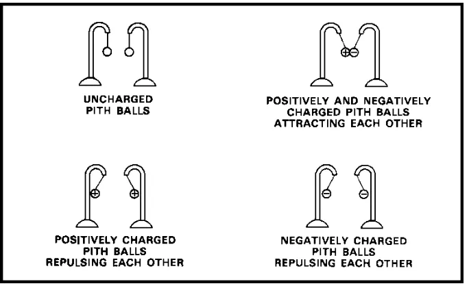
If you briskly rub a rubber rod or comb over a piece of fur or woolen cloth a number of electrons from the fur or cloth adhere to the rubber. If you separate the two immediately, the rubber has an excess of electrons (is negatively charged). If you charge two pith balls oppositely by touching one of them with the rubber and the other with the cloth or fur, they will have an attraction for each other, showing that a force is present. See figure 1-6. You have established a dielectric field. If you allowed the bodies to come together after having been pulled apart, the energy expended in separating them would be regained in the form of force of attraction. This means that energy can be stored in a dielectric field.
Figure 1-6. Pith Ball Experimentation With Dielectric Fields.
both of the pith balls from it. The pith balls would then show a force of repulsion between them, indicating the pressure of a dielectric field.
If you use an external force to bring the two charged pith balls closer together, work is done, and the force of repulsion is increased due to the decrease of the natural distance between the two charged bodies. The energy used in decreasing this distance (recovered when you remove the external force) will be used in returning the pith balls to their original position. Here again, it is shown that energy is necessary to establish a force and that the recovered energy has been stored in the field.
If you isolate one negatively charged pith ball and bring the negatively charged rubber rod toward it from any direction, a force or repulsion will be present. If the pith ball is positively charged, it will have an attraction for a negative charge in any direction. The conclusion is that a dielectric field entirely surrounds a charged body.
The Electroscope. It has been shown experimentally that an electric charge can be detected because it attracts light objects such as pith balls, bits of paper, etc.
Any device used for detecting electric charges is called an electroscope. In its simplest form, an electroscope consists of a pith ball hanging on the end of a silk thread. By touching it with a body of a known charge, you have an instrument that can detect charged bodies and that can indicate the type of charge (polarity). To illustrate, if you touch the pith ball with a glass rod, which has been rubbed with silk, you charge the pith ball positively. Any other charged body that is brought near the pith ball will repel it if the body is positive or attract it if the body is negative. The force of repulsion or attraction indicates the strength of the field surrounding the charged bodies. A better and more sensitive device is the leaf electroscope shown in figure 1-7. It is two thin sheets of metal foil (usually gold or aluminum) called leaves, supported by a wire or stem whose ends pass through a block of sealing wax or insulating material to a metal ball or cap. The leaves are usually sealed in a glass container to prevent air currents and moisture from affecting the instrument. The sensitivity of the instrument depends on several factors, the main two being the thickness and the type of material the leaves are made of.
MM0703, Lesson 1
If the ball receives either a positive or a negative charge, it causes the leaves to spread apart. The leaves spread because like charges repel. When a charge of positive electricity is placed on the leaves, the spread of the leaves will increase when the ball is approached by a positively charged body. On the other hand, a negatively charged body brought near the ball or cap will decrease the spread.
You can place a charge on the leaves by bringing a charged body near, but without making physical contact with, the ball. This is charging by induction. As soon as you remove the charged body, the electroscope is no longer charged unless you provided some means for it to gain or to lose some electrons while the charge was being induced. You can do this by connecting a wire from the electroscope to some neutral conducting object, such as ground. Then, if a charged body is brought near the electroscope, electrons can leave if the charge is negative or enter if the charge is positive. If the wire is disconnected before the charged body is removed, the electroscope will remain charged oppositely to the charge that induced it. This is charging by conduction because the electroscope comes into direct contact with the charged body.
Conductors and Insulators
With certain materials, electrons can be quite readily separated from the atom. In fact, there is much evidence to show that in some metals there are free electrons. Experiments show either that free electrons unattached to atoms do exist or that there is a free interchange of orbital electrons between adjacent atoms. The effect is the same: at any instant, the metal seems full of free electrons. Such material, called a conductor, offers little opposition to the movement of electrons between atoms. While, in general, all metals are good conductors, silver, gold, copper, and aluminum are particularly good.
Materials (such as rubber, glass, silk, fur, mica, and air) which have few free electrons are classed as insulators. Such materials offer great opposition to the movement of electrons between atoms. Materials mentioned previously, on which a charge can be placed by rubbing with a dissimilar material, are insulators. If the center of a long rubber rod is rubbed with a piece of fur, an excess of electrons will locate in the rod's center instead of spreading immediately over the whole surface of the rod.
If, on the other hand, an excess of electrons could be placed at a point on a conductor of uniform cross section, they would immediately spread evenly over the entire surface of the conductor because of the free movement of the electrons.
Since all materials, to some extent, both permit and oppose the movement of electrons, there is no such thing as a perfect conductor or a perfect insulator. Even though there is no sharp dividing line between conductors and insulators, only good conductors are used as conductors and only good insulators are used as insulators.
Distribution of Charges on Objects
Figure 1-8. Distribution of Charges on Different Shaped Objects.
of the charge on the plane, and hence, the charge density of the object. In this way, you would find that the density of the charge on the outside of a sphere is uniformly distributed. On charged objects other than spheres, the greatest density of charge is found on the part which has the greatest curvature or sharpest point. Thus, if a tear-drop-shaped object were charged, the intensity of the electric field would be greatest in the region of the sharp point. The sharper the point, the lower the breakdown voltage for a given separation and the sooner a spark will jump across the gap. That's why lightening rods and some spark gaps are shaped the way they are.
Electrostatic Shielding
If you were to take a hollow spherical conductor with a hole in it, you would find that, regardless of the amount of charge on the outer surface, there would be no charge on the inner surface. You could prove this statement by inserting a proof plane into the charged sphere, making contact with the inner surface, removing the proof plane, and testing it with an electroscope. If any charge were present on the inner surface, a part of it would be transferred to the proof plane and the electroscope would show the presence of the charge. This experiment has always shown no measurable charge.
This property of a closed conductor is the basis of electrostatic shielding, that is, enclosing circuit elements in metal cans to isolate them from outside electric fields.
MAGNETISM
MM0703, Lesson 1
History and Definition
The knowledge of magnetism is very old. The early Greeks knew that certain stones (lodestones), found in the district of Magnesia in Asia Minor, had the apparent magic property of attracting small bits of iron. The reason was the ore in these stones, Fe3O4, called magnetite for the region magnesia. Soon any
substance that possessed the property of attracting bits of iron was called a magnet. Attracted substances are known as magnetic substances. The phenomenon associated with magnets and magnetic materials is known as magnetism.
Magnets can also be man-made. You do it by stroking a steel bar with one end of a lodestone or a magnet or by placing a steel bar in a coil of wire through which an electric current is passed.
Forces Between Poles
If iron filings were sprinkled over a permanent magnet, the greatest concentration of filings would be seen near the end of the magnet (as shown in figure 1-9) with practically none near the center. The regions near the ends of the bar are called the poles of the magnet, and the line joining the two poles is known as the magnet's magnetic axis.
Figure 1-9. Poles of a Magnet.
If a bar is suspended horizontally by a string or mounted on a pivot, it will line up in roughly a north-south direction. Because one end of the bar magnet will always point north, the pole that tends to seek the magnetic north is called the north pole (N). The other, which tends to seek the magnetic south, is called the south pole (S). Thus, the ends of all bar magnets may be marked as north poles or south poles.
Figure 1-10. Repulsion and Attraction of Poles.
scale, he was able to determine how much mechanical torque had to be applied to hold the needle in its zero position when another long magnetic needle was brought near it. Coulomb determined that the force of repulsion between two north poles was inversely proportional to the square of the distance between them. By experimenting with various magnets, he was able to demonstrate that different magnets, when at the same distance, from the suspended magnet, produced different forces. He was able to assign to each magnet a definite pole strength, relative to a standard magnet. He then expressed the results of his investigation as:
2 2 1 2
2 1
d m m
d m m X 1 F
µ = µ
=
where m1 and m2 are the strengths of the poles of the two magnets, d is the
distance between poles, and u a constant, which depends mainly on the medium between the poles. The quantity µ is called the permeability of the medium. When the medium is air, µ is usually considered to be 1. Therefore, µ is left out of the calculations and the formula resolves to:
2 2 1
MM0703, Lesson 1
As an illustration, compare the forces acting on two bar magnets 15 cm long with their north poles 10 cm apart as shown in figure 1-11. Assume the pole strength of each magnet to be 400 units.
Figure 1-11. Forces of Repulsion and Attraction.
Solution:
Force of repulsion between north poles equals
( )
10 1,600dynes. )400 ( ) 400 (
2 =
Magnetic Fields
Characteristics. From the preceding discussion, you have seen that forces act on bar magnets and magnetic materials brought into the surrounding region of another bar magnet. Remember this as you learn the concept of a magnetic field, which is a region wherein magnetic forces act.
A magnetic field surrounds a bar magnet and permeates it. You can see this by placing a glass plate over a bar magnet and sprinkling iron filings on the glass. By tapping the glass, the iron filings will align themselves with the field and will form chains between the north and south poles of the magnet. The chains, referred to as magnetic lines of force, are lines indicating the direction along which a small magnetic compass tends to align itself. Also, it can be seen that the concentrations of iron filings are greatest where the magnetic field is most intense. They have a definite direction and may be thought of as leaving the north pole and reentering the south pole, and then continuing through the magnet from the south pole to the north pole as shown in figure 1-12.
Another interesting effect appears when other magnets are brought into the magnetic field of the first magnet. The alignment of iron filings along the magnetic lines of force between various magnetic pole combinations is shown in figure 1-13.
Although magnetic lines of force are intangible, they have the following six properties:
1. They are continuous and always form closed loops.
Figure 1-12. Magnetic Field About a Bar Magnet.
MM0703, Lesson 1
3. They never cross one another.
4. They are conducted by all materials.
5. When from like poles, they tend to push one another apart when the poles are brought near each other.
6. They concentrate in magnetic materials.
Strength of Magnetic Fields. If you place a magnetic pole of strength in a magnetic field, then from the definition of a magnetic field, a force will act upon the pole. The magnitude and direction of this force will vary from point to point, which means that the magnetic field must have a definite direction and magnitude at each point in space. The direction of a magnetic field is that of the force acting upon an isolated north pole.
The intensity of the magnetic field at any point is defined as the force that would be exerted upon a unit north pole if situated at that point. The intensity of a magnetic field in which a unit magnetic pole experiences a force of one dyne is defined as an oersted (after Hans C. Oersted, a Danish physicist). From this definition, if at any point in a magnetic field a pole strength of M units has a force of F dynes acting upon it, the field intensity H at that point in oersteds will be:
. oersteds M
F H=
Thus, if an isolated pole of 40 units strength, placed at some point in a magnetic field, is acted upon by a force of 240 dynes, the field intensity at that point is:
. oersteds 6 40 240 M F
H= = =
Flux density is a measure of the lines of force per unit of area. The unit of flux density, represented by a letter B, is the gauss. One line of force is known as a maxwell. One maxwell per square centimeter represents a flux density of one gauss. All of these terms will occur again in your study of electricity. Terrestrial Magnetism
A suspended magnet, in orienting itself in a particular direction at every point on or near the earth, shows that the earth is surrounded by a magnetic field. You could think of the distribution of this field as being produced by a huge bar magnet within the earth, located about 17ø away from the earth's axis and having a length much less than the earth's diameter. See figure 1-14.
Since the magnetic pole is away from the geographic north pole, the compass will not point true north (geographic north) over most of the earth's surface. The angle the compass makes with the geographical meridian is called the variation of the compass (declination).
Figure 1-14. Earth's Magnetic Field.
The earth's magnetic field does not remain the same year after year. There are daily, annual, and secular (a period of 960 years) changes. Much work has been done in attempting to explain terrestrial magnetism, but too little is known about the magnetic sources within the earth and atmospheric currents to establish a satisfactory theory of the earth's magnetism.
Theory of Permanent Magnets
If you took a piece of unmagnetized steel and stroked it with a magnet, it would become a permanent magnet. Careful investigation of the process would reveal that no material had been transferred to the bar of steel. The effect apparently takes place upon something already in the steel bar.
Again, if we took a magnetized steel bar and cut it in two pieces, we would then have two magnets (see figure 1-15), and if the process were continued until molecular dimensions were approached, each resulting particle would be a magnet.
[image:23.612.145.549.473.675.2]MM0703, Lesson 1
From this you should be able to assume a working hypothesis that the steel bar, even in its unmagnetized condition, possesses magnetic particles of molecular dimensions distributed throughout the bar randomly. The presence of a magnetic field has the effect of aligning these magnetic particles. This is illustrated in figure 1-16 where you can see the difference between an unmagnetized bar, and a permanent magnet. That poles of a magnet are surface effects reflecting internal conditions is called the molecular theory of magnetism. Recent experimental work in atomic structure assigns the magnetic properties of iron to a large magnetic domain within the atom.
Figure 1-16. Molecular Theory of Magnetism.
Two other terms commonly used in the discussion of magnetic theory are permeability, which is a measure of the relative ease with which magnetic lines of force travel within a material, and reluctance, which is the property of a medium to resist the passing of lines of force. Reluctance corresponds to resistance in an electrodynamic circuit.
Electromagnetism
The discovery by Hans C. Oersted in 1820, that a compass needle is deflected when placed near an electric current was of fundamental importance in that it immediately suggested a connection between electricity and magnetism. The magnet (needle) returned to its original position as soon as the current was zero, or the needle was deflected in the opposite direction if the current was reversed. Since, by definition, a magnetic field is a region where forces act on magnets, you can imply that a magnetic field surrounds the current-carrying conductor. The magnetic field may be represented by line of force as previously mentioned. As with permanent magnets, you can indicate the nature of the field about any shaped conductor with iron filings.
By exploring the field around a very long conductor with a tiny compass needle, you will find that the lines of force are circles with their centers in the wire (see figure 1-17A). A convenient method of remembering the direction of the field about a wire is to recall the left-hand rule. If you mentally grasp the wire with the left hand, holding the extended thumb in the direction of the electron flow, your fingers circle the wire in the direction of the magnetic field.
Figure 1-17. Left-Hand Rule for Magnetic Fields.
MM0703, Lesson 1
The magnetic field of a solenoid is shown in figure 1-19. A solenoid can be made by winding an insulated wire on a cylinder. On exploring the field, either by a compass needle or with iron filings, you will find that the field is quite uniform at the center but, near the ends, the lines of force diverge. Each line of force, however, is a closed loop. The similarity between the field produced by a solenoid and that of a permanent magnet is striking. In fact, a permanent magnet can be replaced by a suitable solenoid as far as exterior magnetic effects are concerned. The best material for solenoids used to make electromagnets is soft iron.
Figure 1-19. Magnetic Field in a Solenoid.
On the basis of experimental data, the following important generalization can be made: Regardless of its origin, a charge in motion will invariably give rise to a magnetic field.
In the discussion of permanent magnets, you learned that the force between magnets was from an interaction between their fields. Hence, if a current has its own magnetic field, there will be a force acting on a conductor carrying a current when it is placed in a magnetic field. This can be illustrated by the following experiment. A solenoid is freely suspended as shown in figure 1-20. A magnet is hung near one end of the solenoid. The magnet is held rigidly, and a current is sent through the solenoid. The solenoid moves toward the magnet. If the current through the solenoid is reversed, the solenoid moves away from the magnet. A force is acting on a conductor carrying current when placed in a magnetic field.
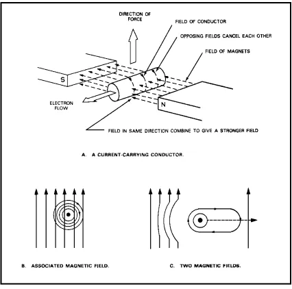
Figure 1-21A shows a useful way for determining the direction of the force exerted on a current-carrying conductor in a magnetic field. Figure 1-21B indicates a current flowing toward you, out of the paper, with its associated magnetic field, superimposed upon a uniform magnetic field. Figure 1-21C shows the effect of the two magnetic fields upon each other. Since the two fields are traveling in the same direction on the left, the resultant field is strengthened. On the right, the two fields are opposing each other and the resultant field is weak-ended. In this case, the net effect is that the conductor will tend to move toward the weaker part of the field.
MM0703, Lesson 1
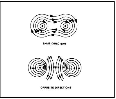
[image:28.612.66.465.163.504.2]Two parallel current-carrying conductors are shown in figure 1-22. The direction of the magnetic lines of force is given by the left-hand rule. If the currents are in the same direction, the two fields cancel in the area between the two conductors. The conductors tend to move in the direction of the weaker magnetic field, and there is attraction between the wires. If the currents are in opposite directions, the two fields add between the wires. The conductors tend to move in the direction of the weaker magnetic field, and there is repulsion.
Figure 1-22. Fields Surrounding Two Adjacent Conductors.
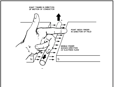
If a conductor is forced to move through a magnetic field, a current is produced in the conductor. There is an easy way to determine the direction of this induced current. Figure 1-23 shows the relationship between the direction of a magnetic field, the direction of motion of a conductor, and the direction on the induced current. It is called the left-hand rule for induced current.
From the foregoing, the following rules can be formulated:
• Conductors carrying current in the same direction tend to be drawn together; conductors carrying current in opposite directions tend to be repelled from one another.
MM 0703, Lesson 1
REVIEW EXERCISES
Circle the letter of the correct answer to each question.
1. What charge will the atom assume if electrons are torn away from a neutral atom?
a. Negative. b. Positive. c. Zero. d. Neutral.
2. What is a substance, the basic component of which is a molecule of unlike atoms?
a. An element. b. A mixture. c. Oxygen. d. A compound.
3. In which direction will the current-carrying conductor in figure 1-24 move?
a. Left. b. Right. c. Up. d. Down.
4. What is an electric current? a. Moving electrolyte. b. Moving electrodes. c. Moving electrolysis. d. Moving electrons.
5. What action will cause current flow through the conductor in to the page in figure 1-25?
a. Move field to right. b. Move conductor to left. c. Move field up.
d. Move conductor up.
6. If conductor X is fixed, in figure 1-26, W will move in what direction? a. Right.
Figure 1-24. Figure 1-25. Figure 1-26.
7. How is the magnetic field around a current-carrying conductor described? a. Permanent and natural.
b. Temporary-artificial. c. Permanent-artificial. d. Temporary and natural.
8. What represents the angle that the compass makes with the geographical meridian?
a. Inclination. b. Accident. c. Declination. d. Incident.
9. What position do electric circuits tend to take so that their currents will satisfy what conditions?
a. Be perpendicular and flow in opposite directions. b. Be parallel and flow in the same direction.
c. Be parallel and flow in opposite directions. d. Be perpendicular and flow in the same direction.
10. A bar magnet with a cross section area of 2 sq cm contains 1,000 lines of magnetic force. What is the flux density of the magnet?
MM 0703, Lesson 1
11. What is the direction of the resultant magnetic field at point P in figure 1-27?
a. ↑ b. → c. ↓ d. ←
Figure 1-27.
12. A magnetic pole of 50 unit poles strength exerts a force of 200 dynes upon a second pole 5 cm distance in the air from the first pole. What is the strength, in UP (unit poles), of the second pole?
a. 200. b. 198. c. 100. d. 6.
13. Assume that the magnetic poles are concentrated at the ends of the magnets. What force exists between the south poles? See figure 1-28. a. 4,000 dynes attraction.
b. 4,000 dynes repulsion. c. 100 dynes attraction. d. 100 dynes repulsion.
14. What is the force of repulsion, in dynes, between the two north poles in figure 1-29? (Do not consider forces exerted by the south poles.) Pole strength of each magnet is 800 units.
a. 25,600. b. 25,824. c. 12,784. d. 6,327.
Figure 1-29.
15. What is the smallest component into which a compound can be subdivided by physical means?
a. An electron. b. A proton. c. A molecule. d. An atom.
16. How is the resultant field affected by lines of force in the same direction in a magnetic field?
a. Reinforced. b. Canceled. c. Attenuated. d. Neutralized.
17. What material is normally used as an insulator? a. Zinc.
MM 0703, Lesson 1
18. What difference exists between balanced atoms of various elements? a. Number and arrangement of electrons and protons.
b. Number and size of electrons and protons. c. Number and weight of electrons and protons. d. Number and polarity of electrons and protons. 19. What is the unit of measure of magnetic field intensity?
a. Dyne. b. Gauss. c. Coulomb. d. Oersted.
20. What is the resulting action when a conductor is moved rapidly through a continuous magnetic field?
a. The magnetic field will be canceled. b. The magnetic field will be neutralized. c. Current will flow in the conductor. d. Current will not flow in the conductor.
Lesson 2 CIRCUITS
Task. The skills and knowledge taught in this lesson are common to all missile repairer tasks.
Objectives. When you have completed this lesson, you should be able to explain what an electric circuit is, define the standard electrical units of measure, and explain and use Ohm's and Kirchoff's laws.
Conditions. You will have this subcourse book and work without supervision. Standard. You must score at least 75 on the end-of-subcourse examination that covers this lesson and lessons 1, 3, and 4 (answer 29 of the 38 questions correctly).
AN ELECTRIC CIRCUIT
Before discussing direct current and the laws which apply to it, you need to understand the elements of a direct or alternating circuit as well as electromotive force and resistance. An electric circuit is formed when a source of electrical potential is connected to an electrical device by means of a conductor. Figure 2-1 shows a simple circuit with circuit components.
Terminology
Electrical Potential. The potential (in this case, a battery) provides the driving force for the circuit. Since the negative terminal of the battery has
MM0703, Lesson 2
an excess of electrons, as compared to the positive terminal, the electrons move from the negative to the positive terminal when there is a completed path.
Conductor. The item which provides this path for the electrons is the conductor. The phenomenon which allows this conduction is at the atomic level. Electrons are not readily separated from an atom because they are maintained within the atom by the attraction force of the positive nucleus. However, electrons are known to exist in a free state apart from the atom. Such electrons are called free electrons. Some substances such as copper, silver, gold, and aluminum contain great quantities of these electrons and are good conductors. Although all conductors offer some opposition to current flow, you can assume this opposition is negligible here.
Electrical Device. In order to use the electrons flowing in the conductor, an electrical device must be inserted. As the electrons pass through the device, they activate the device. In figure 2-1, the electrical device is a lamp.
Switch. A switch allows you to start and stop the flow of electrons. When you close the switch (start electron flow), a closed circuit is formed, and when you open the switch (stopping current flow), an open circuit is formed.
Fuse. If the electron flow in a circuit is too great, it may damage the electrical device or excessively heat the conductors. To prevent this, a fuse can be inserted. Excessive electron flow produces sufficient heat to melt the fuse and open the circuit, turning it off. A fuse may be considered as an automatic safety switch.
Kinds of Circuits
Series. Series circuit provides only one path for current to flow. So the current flows through the first resistor, then the second, etc. in series.
Parallel. In a parallel circuit, the current has parallel paths through which it can flow. Each resistor has one end connected to the battery, and the other end is connected to the other end of the battery. The line current or total current leaving the battery must equal the sum of the currents entering the parallel branches.
ELECTRICAL MEASUREMENTS
In order to learn any more about electrical phenomena, you need to learn the five basic electrical quantities and to specify the units by which they are measured. Other definitions will be added as the need arises.
Coulomb
6,280,000,000,000,000,000 (6.28 X 10 ) free electrons on a single charged body. Although this large unit is seldom used in calculations, it is important because it is the basis for the definition of other units.
Ampere
The unit of electron flow is called the ampere (amp). If one C of charge passes a given point on a wire in 1 second, then 1 amp is said to flow. In other words, the ampere is a special name given to a C per second. This electron flow is called current and is represented by the symbol I, which is an abbreviation for "intensity of flow."
Ohm
The practical unit of resistance to electric current flow is called the ohm. It is that resistance in which 1 volt will maintain a current of 1 amp. The symbol for ohms is Ω, which is the Greek letter omega.
Volt
The unit of electromotive force (pressure) is the volt. It is the force that will cause 1 amp to flow through a resistance of 1 Ω. Voltage is represented by the symbol V or E.
Watt
The unit of electrical power is the watt (W). There is one watt of power in a 1-Ω resistor in which a current of 1 amp is flowing. The basic formula is P = IE.
Practical Values of Electrical Terms
Because it is difficult to visualize the size of these units from the definitions, the following information may be helpful. You can get a better idea of the size of the C by imagining that, if a charge of 6.8 millionths of a C were placed 1 ft from a similar charge, there would be a repelling force of 1 lb. acting between them. A 100-W light takes about 1 amp of current. The resistance of an electric toaster or flat iron is about 25 Ω.
ELECTROMOTIVE FORCE
MM0703, Lesson 2
Figure 2-2. Electromagnetic Force.
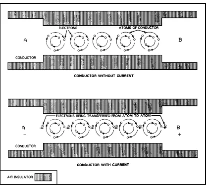
CURRENT
To understand the electron flow produced by an EMF, consider the behavior of electrons in a copper wire. At any instant, the copper wire has free electrons drifting about within the wire. These electrons are attached to the positively charged body and repelled by the negatively charged body. The movement of these free charges through the copper wire makes an electric current. Current flow, as visualized in the electron theory, is illustrated in figure 2-3. AB is a conductor, composed of atoms (enlarged many, many thousands of times in the illustration), each of which is made up of electrons revolving about its center (including free electrons around the outer orbits). When an EMF is impressed across AB, electrons tend to transfer from atom to atom, from the A end to the B end. This electron movement is current and can be defined as a moving charge.
RESISTANCE
Resistance is produced by any device in a circuit which offers a continuous opposition to current flow. Energy in some form is dissipated when the EMF overcomes this resistance and causes current to flow. In many cases, resistance is added in a circuit, not to dissipate useful energy, but to improve overall operation. These types of resistors are classified as wire-wound or carbon. The wire-wound variety is made of resistance wire such as nichrome, German silver, or manganin. Carbon resistors are made by mixing powdered carbon with some suitable binder. The mixture is molded into the proper shape. Resistors, can be fixed, adjustable, or variable.
Fixed
Figure 2-3. Electron Behavior.
Adjustable
Adjustable resistors are used to adjust the value of the resistance in a circuit to compensate for changes in resistor values due to age. The adjustable resistor is usually wire-wound and has one or more sliding collars which may be moved along the resistance element to the desired resistance value. It is then clamped into place and remains fixed until the value changes when it must be readjusted.
Variable
MM0703, Lesson 2
requirements, variable resistors are either carbon or wire-wound. The resistance element of the variable resistor is usually circular. The sliding tap (arm), which makes contact with it, has a knob and a shaft with which the resistance can be smoothly varied. Variable resistors are called rheostats or potentiometers. LAWS
Kirchoff's Laws used with Ohm's Law makes the solutions of many problems very simple. Application of Ohm's Law is the same for any circuit. Application of Kirchoff's Laws is shown for all three kinds of circuits; series, parallel, and series-parallel.
Ohm's Law
Ohm's Law states; The current in a circuit is directly proportional to the applied potential (voltage) and inversely proportional to the resistance. It is written mathematically as follows:
R E I=
where I = current in amps, E = EMF in V,
R = resistance in Ω.
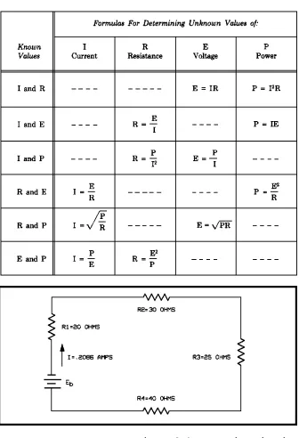
This law is based on the findings of George Simon Ohm in 1827. It shows that the amount of current that flows in a circuit increases if the potential applied is increased and decreases if the resistance is increased. It also shows that current decreases when the potential applied decreases, and increases if the resistance decreases. To further understand Ohm's Law, you have to understand the relationships between current, voltage, resistance, and power. Review the paragraph, Electrical Measurements, if you are unsure. Table 2-1 shows Ohm's Law as applied to direct current (DC) and alternating current (AC) circuits. The next lesson is on AC and DC.
The following are some applications of Ohm's Law.
Look at figure 2-4. The EMF is 24 V and the resistance is 60 Ω. Solve for current.
Step one--copy formula for I:
R E I=
Step two--substitute known values:
Ω =
60 V 24 I
Step three--perform indicated division: I = .4 A.
Table 2-1. Ohm's Law.
Figure 2-4. A Series Circuit.
Suppose in figure 2-4, the I is .4 A and the EMF is 24 V. Solve for resistance. Ω
= =
= 60
A 4 .
V 24 I E R
MM0703, Lesson 2
When current flows through a resistor, a voltage is developed across the resistor. The voltage developed on a resistor is often called a voltage drop. Ohm's Law applies to this voltage drop. Here are some examples.
Suppose R1 = 20Ω and IR1 = .4 A. Solve for ER1, the voltage drop on R1.
ER1 = IR1 X R1 = .4A X 20 Ω = 8V.
Suppose ER2 = 60V, and R2 = 30 Ω. How much is I2?
A 2 30 V 60 R E I 2 2 2 = Ω = =
Suppose ER3 = 20 V and IR3 = 2A. How much is R3?
Ω = = 10 A 2 V 20 R3 Kirchoff's Laws
Kirchoff's Laws are also used to solve for voltages, currents and resistances. Current. Kirchoff's Law for current is that the sum of the currents entering a point is equal to the sum of the currents leaving a point.
In a series circuit there is only one path for current to flow, so IT = IR1 = IR2 = IR3 etc.
In figure 2-4, if the total current flowing is .4 A, then IR1, the current flowing in R1, is .4A; IR2, the current flowing in R2, is .4 A; and IR3, the current flowing in R3, is .4A.
In figure 2-5 is a parallel circuit. In it, according to Kirchoff, IT = IR1 + IR2.
Let
IR1 = .2A and
IR2 = .6A. Then
IT = .2A + .6A = .8A.
In the series-parallel circuit, shown in figure 2-6, R3 is a series resistor. R1 is in parallel R2. R3 is called a series resistor because it is the only path through which line current (total current) can flow into the circuit. R1 and R2 make up a parallel combination. The current leaving R3 enters R1 and R2, two parallel paths for current to flow. That is, I3 = IT and I1 + I2 = IT. In figure 2-6,
let
Figure 2-5. A Parallel Circuit.
Figure 2-6. A Combination Series-Parallel Circuit.
Then let I1 = .3A and
I2 = .2A. Then
IT = I1 + I2 = .3A + .2A = .5A
MM0703, Lesson 2
For the series circuit in figure 2-4: ER1 + ER2 + ER3 = Eb (EA or EMF). For example,
let
ER1 = 8V, ER2 = 12V, ER3 = 4V. Then
EA = ER1 + ER2 + ER3 = 8V + 12V + 4V = 24V.
For the parallel circuit in figure 2-5: ER1 = EA because R1 is the only resistor in its loop. Likewise ER2 = EA for R2 is the only resistor in its loop. So EA = E1 = E2.
For example, let
EA = 24V. Then
ER1 = 24V, and
ER2 = 24V.
For the series-parallel circuit of figure 2-6: ER3 + ER1 = EA because R3 and R1 are the only resistors in their loop. Likewise ER3 + ER2 = EA.
For example, let
ER3 = 15V and
ER2 = 30V. Then
EA = ER3 + ER2 = 15V + 30V = 45V.
Resistance. Kirchoff's Laws for resistance follow from the laws for current and voltage. Actually Kirchoff stated only two laws, one for voltage and one for current. The principles for resistance are mathematical derivations from Kirchoff's Laws for voltage and current.
In a series circuit, total resistance equals the sum of the individual resistances. That is, in figure 2-4, RT = R1 + R2 + R3.
For example in figure 2-4, let
R1 = 20Ω, R2 = 30Ω, and
R3 = 10Ω. Then
In a parallel circuit, the total resistance equals the reciprocal of the sum of the reciprocals of the resistors. (Recall that the reciprocal of a number is one divided by that number.)
So, in figure 2-5, . R 1 R 1 1 R 2 1 T + =
This is called the reciprocal formula for total resistance of resistors in parallel.
For example in figure 2-5, let
R1 = 120Ω and
R2 = 40Ω Then 120 3 120 1 1 40 1 120 1 1 R 1 R 1 1 RT 2 1 = = = = + = 30 4 120 4 120 X 1 120 4 1
RT= = = =
If there are only two resistors in parallel, then the reciprocal becomes : here shown as R R R R 2 1 2 1 + × 2 1 1 2 2 1 1 2 1 2 2
1 R R
R R 1 R R R R R R 1 R 1 R 1 1 RT × + = × + × = + = 1 2 2 1 1 2 2 1 R R R R R R R R 1 RT + × = + × × =
This is known as the product-over-the-sum formula for two resistances in parallel.
If all the resistors in parallel are equal, the reciprocal formula becomes RT = R1 Rn, where R1 is value of one resistor, and Rn is number of resistors.
Proof: In figure 2-5 if R1 = R2, then the reciprocal formula . R 1 R 1 1 R 1 R 1 1 1 1 2 1 + = + Now 2 R 2 R 1 R 2 1 R 1 R 1
1 1 1
1 1 1 = × = = +
MM0703, Lesson 2
Series-parallel circuit resistance is found by adding resistance of series resistors to the equivalent resistance of combinations. Combinations may be resistors in parallel or in series with each other but not with the battery. The symbol for the equivalent resistance of the combination of R1 and R2 in parallel with each other may be Req1, 2 or Rc1, 2 or Rpar 1, 2. The tags of schematic numbers may be omitted if there is only one combination in the circuit.
In figure 2-6, let
R1 = 100Ω, R2 = 150Ω, and
R3 = 30Ω. Then
RT = R1 + Req2,3 (Kirchoff's Law). Now, ) sum the over product ( R R R R q Re 2 1 2 1 3 ,
2 − − −
+ × = Substituting Ω = = + × = 60 250 000 , 15 150 100 150 100 q
Re 2,3
So,
RT + RC + 60Ω = 90Ω.
POWER
Power is work done. Power is a product of voltage and current. The formulas for power are
P=EI P=I2R
R E P
2
=
The most commonly used are EI and I2R. I2R losses is a term commonly used by electric power companies transferring power through miles of wire from the generator on a dam to a city.
The basic unit of measurement of power is the watt. Standard units are kilowatt (kW), megawatt (MW), milliwatt (mW), and microwatt (µW).
Power dissipated is power used (consumed) by resistance. It may be in the form of heat, as in a toaster, oven, or iron. The power ratings of components in electrical circuits are often 2-1/2 times as much as would be dissipated in the circuit.
SPECIAL-CASE PROBLEM SOLVING
Ohm's law, as previously stated, is Where: I is the current in amperes,
E is the EMF in volts,
R is the resistance in ohms, P is the power in watts,
EI P then , IR E , I E R , R E
I= = = =
Problem 1. Find the total resistance of the circuit in figure 2-7. Solution:
RT = R1 + R2 + R3 = 20 + 30 + 10 = 60Ω
Problem 2. Find the total current flowing in the circuit in figure 2-7. Given:
Eb = 24V RT = 60Ω Solution:
R E I=
amp 4 . 60 24 IT= =
Problem 3. Find the voltage drops across each resistor in the circuit in figure 2-7.
Solution: E = IR
Solving for ER1, E = .4 x 20 = 8 V. Solving for ER2, E = .4 x 30 = 12 V. Solving for ER3, E = .4 X 10 = 4 V.
Assuming Eb = 24 V, Eb = ER1 + ER2 + ER3 = 8 + 12 + 4 = 12 V.
MM0703, Lesson 2
Problem 4. Find the value of R3 in the circuit of figure 2-8. Given:
E = 24V I = .5 amp
With E and I known, you can solve for RT. Solution:
I E R=
Ω =
= 48
5 . 24 RT
Then,
R3 = RT - R1 - R2 = 48 - 10 = 8Ω.
Problem 5. Prove that Eb in the circuit in figure 2-8 equals 24 V. Given:
I = .5 amp R = 48Ω Solution:
E = IR
Eb = .5 X 48 = 24V
Problem 6. Find the total resistance in the circuit of figure 2-9. Given:
E = 24V I = 6 amps Solution:
I E R=
Ω =
= 4
6 24 RT
applied voltage are all known values. Referring to Kirchoff's law (current coming out of a branch is equal to the current entering the branch), at point A there are 6 amps of current and at point B there must be this same 6 amps of current. Notice at point A there are three paths for current flow. The same voltage (potential) is felt across each path.
Given: where
IT = IR1 + IR2 + IR3, Solution: amp 4 . 2 10 24 IR1= =
amp 2 . 1 40 24 IR2 = =
Then,
IR3 = IT - IR1 - IR2 = 6 - 2.4 - 1.2 = 2.4 amp. Ω = = 10 4 . 2 24 3 R or 20 5 1 20 2 20 1 20 2 1 10 1 20 1 10 1 1 3 R 1 2 R 1 1 R 1 1 RT = + + = + + = + + = Ω = × 4 5 20 1
Problem 8. Find the total power consumed in the circuit of figure 2-9; Solution.
P = 1E
PT = IT = 6 X 24 = 144W, or
PT = I2R = 36 X 4 = 144W,
[image:49.612.60.553.91.713.2]or , W 144 4 576 R E PT 2 = = =
MM0703, Lesson 2
Problem 9. Find the total resistance of the series-parallel circuit in figure 2-10. The first problem is to find the equivalent resistance of R2 and R3, which are in parallel. Once you find this value, the resistance of the branch is referred to as RA then,
Solution: Ω = = + × = + × = 10 40 400 20 20 20 20 3 R 2 R 3 R 2 R RA
With the value of RA known, the circuit can be handled as a series circuit in calculating the total resistance:
RT = R1 + RA + R4 = 10 + 10 + 20 = 40Ω.
Problem 10. Find the current flowing in the circuit of figure 2-10; Solution: R E I= amp 6 . 40 24 R E I T b
T = = =
Problem 11. Find the voltage drop across each resistor or branch in the circuit of figure 2-10;
Solution:
E = IR.
[image:50.612.65.415.368.615.2]ER1 = .6 X 10 = 6V ERA = .6 X 10 = 6V ER4 = .6 X 20 = 12V
Problem 12. Find the current flow through R2 and R3 (figure 2-10). Given:
IT = .6 amp ERA = 6V Solution:
R E I=
amp 3 . 20
6 2 R
I = =
amp 3 . 20
6 3 R
I = =
MM0703, Lesson 2
REVIEW EXERCISES
Circle the letter of the correct answer to each question. 1. What is the basic power formula?
a.
E I P=
b.
A E P=
c. P = IE. d. P = EA.
2. What is the unit of electrical power? a. The ampere.
b. The gauss. c. The volt. d. The watt.
3. What symbol represents current? a. R.
b. I. c. P. d. A.
4. What is the unit of electromotive force? a. The coulomb.
b. The ampere. c. The watt. d. The volt.
5. What is the total resistance of the parallel circuit containing resistors of 10 Ω and 15 Ω?
MM0703, Lesson 2
6. What is the electrical resistance formula?
a.
I W R=
b.
E I R=
c.
I E R=
d.
W I R=
7. What is the total resistance of a parallel circuit containing five 40-Ω resistors?
a. 8. b. 16. c. 32. d. 64.
8. A circuit consumes 5 W of power from a potential of 50 V. What is the resistance, in Ω, of this circuit?
a. 25. b. 250. c. 500. d. 5,000.
9. What potential, in V, will cause .2 amps of current to flow through 1,000 Ω of resistance?
a. 30. b. 200. c. 300. d. 2,000.
10. What is the total resistance in Ω in figure 2-11? a. 40.
Figure 2-11.
11. How much current, in amps, will flow in the circuit in figure 2-11? a. .05.
b. .5. c. 5. d. 50.
12. How much power in W, is consumed in the circuit in figure 2-11? a. 2.5.
b. 5.5. c. 25. d. 55.
13. How many V are dropped across resistor R1 in figure 2-11? a. 30.
b. 32. c. 40. d. 42.
14. How much power, in W, is dissipated across resistor R1 in figure 2-11? a. 5.
b. 10. c. 15. d. 20.
15. How much power, in W, is dissipated across resistor R3 in figure 2-11? a. 5.5.
MM0703, Lesson 2
16. What is the total resistance in Ω in figure 2-12? a. 2.5.
b. 5. c. 7.5. d. 10.
17. How many amps of current flow through resistor R1 in figure 2-12? a. .1.
b. 1. c. 2. d. 4.
18. How much power, in W, is dissipated across resistor R3 in figure 2-12? a. 10.
b. 20. c. 30. d. 40.
19. What is the total power, in W, consumed by the circuit in figure 2-12? a. 40.
[image:56.612.58.544.63.599.2]b. 60. c. 80. d. 100.
20. What is the Ohms Law formula for computing current?
a.
R E I=
b.
E R I=
c.
V E I=
d.
E V I=
MM0703, Lesson 3
Lesson 3
DIRECT AND ALTERNATING CURRENTS
Task. The skills and knowledge taught in this lesson are common to all missile repairer tasks.
Objectives. When you have completed this lesson, you should be able to explain the characteristics of direct and alternating currents; the generation of a sine wave of voltage or current; vector representation of a sine wave; and peak, average, and effective values of alternating current.
Conditions. You will have this subcourse book and work without supervision. Standard. You must score at least 70 on the end-of-subcourse examination that covers this lesson and lessons 1, 2, and 4 (answer 27 of the 38 questions correctly).
DEFINITION Direct Current
A direct current (DC) exists when a number of electrons move in one direction only, from a point of low potential to a point of high potential. For example, when the circuit of a flashlight is completed by the switch, electrons continue to move from the negative terminal toward the positive terminals through the filament of the bulb, as long as the switch is on.
Alternating Current
In an alternating-current (AC) circuit, the electrons move through the circuit in one direction for a short period of time, and then move back in the other direction for a like period of time, changing direction at definite intervals. It is this characteristic that gives it its name. The electrons also move toward a point of higher potential, but this point changes from one side of the circuit to the other. In other words, the polarity of the applied alternating voltage changes causing the direction of current flow to change. The two systems are illustrated in figure 3-1.
History
In the beginning of the electrical age, only DC existed. It worked well because energy was consumed relatively close to where it was generated. However, as the demand for electric energy increased, energy had to be transmitted over greater distances. Because power is lost in long-distance lines, DC had to be improved upon.
The solution to the problem came on August 31, 1831, when Michael Faraday wound two separate coils of wire upon an iron ring. The ends of one coil were connected to a battery and switch. The ends of the other coil were joined by a long wire, which passed over a compass needle. When the switch was closed completing the battery circuit, the compass needle moved, then oscillated back and forth, and finally stopped in its original position. When the switch was opened, the needle again moved, in the opposite direction, oscillated, and came to rest. This momentary flow of current was completely unexpected, and Faraday had difficulty explaining it. Later he showed that magnetic and electrical actions were reciprocal because it is necessary for electricity to move before a magnetic effect is produced, and it is necessary for magnetism to move (or change) before an electrical effect is produced. Based on this discovery, AC systems were soon developed that greatly reduced this power loss during transmission. Alternating current systems work so well, they are now used almost exclusively in powerlines.
All forms of communications are based upon variations in the AC transmitting medium that can, for instance, mirror the variation in sound waves your voice produces. In order to communicate by telephone or radio, sound waves must be made to cause electrical variations in the transmitter and receiver. Alternating currents can accommodate these electrical variations. Thus can the intelligence in the sound waves be transmitted electrically.
Direct current is simple, but the generation and characteristics of AC are complex. The rest of this lesson is on AC.
GENERATION OF CURRENT AND VOLTAGE BY AN AC SYSTEM Principles
An AC generator converts mechanical energy into electrical energy. It does this by the principle of electromagnetic induction. A review of this principal follows.