Comparative Study on Finite-Precision Controller Realizations
in Different Representation Schemes
Jun Wu , Sheng Chen
and Jian Chu
National Key Laboratory of Industrial Control Technology Institute of Advanced Process Control
Zhejiang University, Hangzhou, 310027, P. R. China
Department of Electronics and Computer Science University of Southampton, Highfield
Southampton SO17 1BJ, U.K.
Abstract
: A computationally tractable finite word length (FWL) closed-loop stability measure is derived which is applicable to fixed-point, floating-point and block-floating-point representation schemes. Both the dynamic range and precision of an arithmetic scheme are considered in this new unified measure. For each arith-metic scheme, the optimal controller realization prob-lem is defined and a numerical optimization approach is adopted to solve it. Two examples are used to illustrate the design procedure and to compare the optimal con-troller realizations in different representation schemes.Keywords — digital controller, finite word length,
arith-metic scheme, closed-loop stability, optimization.
1
Introduction
In recent years, there has been a growing interest in dig-ital controller implementation which reduces the FWL effects on closed-loop stability. It is well known that a control law can be accomplished with different realiza-tions and that the parameters of a controller realization are represented by a digital processor of finite bit length in a particular format, namely fixed-point, floating-point or block-float-point format. Previous works [1]–[4] have derived some FWL closed-loop stability measures for these three formats, respectively, and defined the corre-sponding optimal controller realization problems based on these measures. However, all these previous measures are only linked to the precision bit lengths of the respec-tive representation schemes used and do not consider the dynamic range bit lengths. Arguably, a better approach is to consider some measure which has a direct link to the total bit length required. The main contribution of this paper is to derive a unified FWL closed-loop
J. Wu and S. Chen wish to thank the support of the UK Royal So-ciety under a KC Wong fellowship (RL/ART/CN/XFI/KCW/11949). J. Wu and J. Chu wish to thank the support of National Natural Sci-ence Foundation of China (Grant Ref.60174026), Zhejiang Provincial Natural Science Foundation of China (Grant Ref.699085) and Doctor Degree Programs Foundation of China (Grant Ref.1999033571).
bility measure that can accommodate both the dynamic range and precision requirements and is applicable to all the three schemes.
2
Number Representation Schemes
When is represented in the fixed-point scheme of
bit length
, the bits are assigned as
fol-lows: one bit for the sign, bits for the integer part and
bits for the fraction part. Assuming that no overflow
occurs, which means that
, is perturbed to
Æ Æ
(1)
Any can be expressed uniquely as
, where is the sign of ,
is the mantissa of ,
is the
exponent of ,denotes the set of integers and the floor
function is the closest integer less than or equal to .
When is stored in the floating-point format of bit length
, the bits consists of three parts: one
bit for,
bits for
and
bits for
. Letandbe
the lower and upper limits of the exponent, respectively.
Clearly,
. Denote the set of integers
as . Assuming that no underflow or
overflow occurs, which means that the exponent of is within
, is perturbed to
Æ
Æ
(2)
In the block-floating-point format, a set of real numbers
is first divided into some blocks. For an illustrative
purpose, consider the case of dividing into the two
non-empty and non-overlapped subsets and . Let be the element in that has the largest absolute
value, and
be the element in
that has the
largest absolute value. Then, any can be expressed
uniquely as
, where is the
block mantissa of , and the block exponent of is
When all the elements in are presented in the
block-floating-point format of bit length
,
the bits are assigned as follows: bit for the sign,
bits for which is represented in fixed-point with the two’s complement system, and
bits for
. Letand
be the lower and upper limits of the block exponent,
respectively. Obviously,
. Denote
(4)
Assuming no underflow or overflow, i.e. the block expo-nent of is within
, is perturbed to
Æ
Æ
(5)
For the notational conciseness, we introduce the “gen-eralized” dynamic range bit length and precision bit
length
for the three representation schemes. It is
un-derstood that ,
or
and
,
or
,
depending on which format is actually used.
3
Problem Statement
The discrete-time linear time-invariant plant is
de-scribed by
(6)
with
,
and
; and the generic digital controlleris described by
(7)
with
,
,
,
and
. Let
with the command input . Then and form
a closed-loop control system. Assume that a
realiza-tion
of has been designed. It
is well-known that the realizations ofare not unique.
All the realizations ofform the realization set
(8)
where
is any nonsingular matrix. Let
, wheredenotes the column
stack-ing operator, and ,
,
,
,
,
,
,
and
be similarly defined. Denote
(9)
where and
is the trans-pose operator. We also refer toas a realization of.
The stability of the closed-loop system depends on the eigenvalues of the matrix
(10)
All the different realizations have the same set of
closed-loop poles if they are implemented with infinite precision. Since the closed-loop system is designed to be stable, the eigenvalues
(11) Define
(12)
and the indexof representation formats adopted
fixed-point format
floating-point format
block-floating-point format
(13)
The controller realization is implemented in format
of dynamic range bits,
precision bits and one
sign bit. In the remainder of this paper, it is assumed that ifis stored in the block-floating-point format, it is
divided into “natural” blocks of ,
,
,
and
. Let
be the element in
which has the
largest absolute value. The elements ,
,
and
are similarly defined. Denote
(14)
4
Optimization of an FWL
Closed-Loop Stability Measure
Firstly, the dynamic range bit length of bits must be
large enough to accommodate. We define a dynamic
range measure for realizationin formatas
Û
Û
ÞÛ
ÞÛ
(15)
Proposition 1 The realization can be represented in
the fixed-point format of integer bits without
over-flow, if
; can be represented in the
floating-point format of
exponent bits without
under-flow or overunder-flow, if
Û
Û
; can
be represented in the block-floating-point format of
block exponent bits without underflow or overflow, if
ÞÛ
Let
be the smallest dynamic-range bit length that, when used to implement with format , does not
cause overflow or underflow.
can
eas-ily be computed by:
when ,
when and
when , where the ceiling function denotes
the closest integer greater than or equal to . Note
that the measure defined in (15) provides an
es-timate of as (16)
It can easily be seen that
and, when the fixed-point format is adopted,
.
For a vector , let be the vector of the same
dimen-sion whose elements are alls and denote
(17)
For two vectors
and
of the same
dimension, define the Hadamard product of andas
Æ
. When the dynamic range of
represen-tation formatis sufficient, according to the results of
Section 2,is perturbed to Ædue to the
effect of finite where (18)
Each elementÆ of
is bounded by
, that is,
. With the perturbation ,
is moved to
Æ. If
an eigenvalue of Æ is outside the
open unit disk, the closed-loop system, designed to be stable, becomes unstable with the finite-precision imple-mented in format. It is therefore critical to know
when the FWL error will cause closed-loop instability. From a first-order approximation,
Æ Æ ¡¼ Æ (19)
For the derivative ¡ Æ , define Æ (20) Then Æ ¡¼ (21)
This leads to the following precision measure for real-izationin format
¡ ¡¼ (22)
Obviously, if , then
Æ which means that the closed-loop
remains stable under the FWL error. In other words,
for a given implemented in format with a
suffi-cient dynamic range, the closed-loop can tolerate those
FWL perturbations whose norms are less
than . It is easy to see that
¡¼ Æ (23)
and from the results of [2], it can be shown that the value of can be computed explicitly.
Under the condition that the dynamic range is sufficient,
that is,
, the perturbation and
there-fore the precision bit length
determines whether the
closed-loop remains stable. Let
be the smallest precision bit length that, when used to implementwith
format, guarantees the closed-loop stability. From the
precision measure , an estimate of is given as (24)
Define the minimum total bit length required in the im-plementation ofwith formatas
(25)
Clearly,implemented with a bit length
can guarantee a sufficient dynamic range and closed-loop
stability. Combining the measures and
results in the following true FWL closed-loop stability measure for the given realizationwith format
(26)
An estimate of
is given by as
(27)
The measure provides the FWL characteristics
of a realizationin a given format. The optimal
con-troller realization problem in formatis formally
Define the following optimization criterion in format:
Æ
Û
(29)
The optimal realization problem (28) can then be posed as the following optimization problem:
Ì
Ì
(30)
Given
, the optimal realization
can
readily be computed. By setting ,and,
respec-tively, in the optimization problem (30), we can attain the optimal fixed-point realization
, the optimal
floating-point realization
and the optimal
block-floating-point realization
.
5
Two Design Examples and Result
Comparison
In Example 1, the closed-loop system contained a plant with and a reduced-order observer-based
con-troller with . Based on the proposed unified FWL
closed-loop stability measure, the optimization problem (30) was formed. Using the MATLAB routine
fmin-search.m, this optimization problem was solved for
, and, respectively, to obtain the optimal
realiza-tions
,
and
. In Example 2, the
closed-loop system contained a plant with and
a output-feedback controller with . Using the
same procedure for Example 1, the optimal realizations
,
and
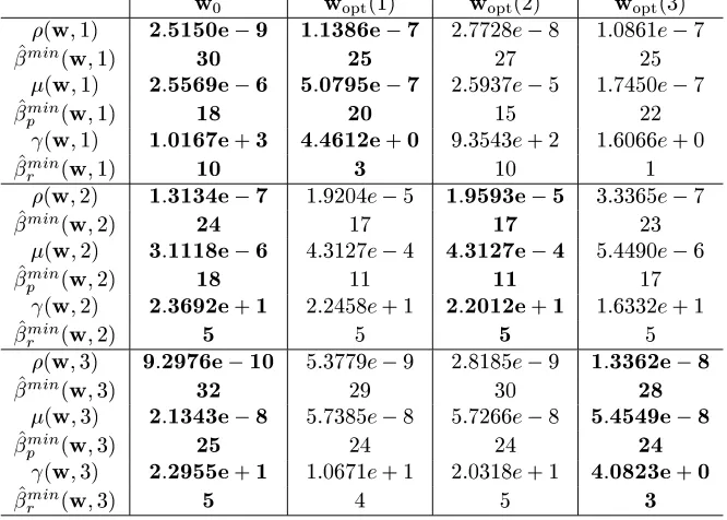
were obtained. Table 1
lists the values of the measures,andin the three
different representation schemes together with the cor-responding estimated minimum bit lengths for
and
of Example 1. Table 2 does the same thing for
Example 2. As far as the robustness of FWL closed-loop stability is concerned, given an arbitrary realiza-tion, floating-point representation is not necessarily bet-ter than fixed-point or block-floating-point one. For ex-ample, floating-point is the best format to implement the initial realization
of Example 1 while fixed-point is
the best format to implement
of Example 2.
How-ever, as expected, the optimal floating-point realization
implemented in floating-point format is always
the best in terms of robustness to FWL errors. Also the results in Table 1 show that fixed-point format is better than block-floating-point format to implement
of Example 1 for , while the results of
Ta-ble 2 indicate that the opposite is true for Example 2. This simply confirms the fact that the performance of block-floating-point scheme critically depends on how
to divideinto blocks. With a proper division,
block-floating-point scheme should beat fixed-point scheme in terms of robustness to FWL errors. Table 3 compares the true minimum required bit lengths
,
and
of
implemented in the three different schemes
with those of fixed-point implemented
,
floating-point implemented
and block-floating-point
im-plemented
of Example 1, respectively. Table 4
does the same thing for Example 2.
6
Conclusions
We have proposed a design procedure for optimal con-troller realizations in different representation schemes. The procedure provides designer with useful quantita-tive information regarding robustness to FWL errors and estimated minimum bit length for guaranteeing closed-loop stability. This allows designer to choose an opti-mal controller realization in an appropriate representa-tion scheme to achieve best computarepresenta-tional efficiency and closed-loop performance.
References
[1] G. Li, “On the structure of digital controllers with finite word length consideration,” IEEE Trans.
Au-tomatic Control, Vol.43, No.5, pp.689–693, 1998.
[2] J. Wu, S. Chen, G. Li, R.S.H. Istepanian and J. Chu, “An improved closed-loop stability related measure for finite-precision digital controller real-izations,” IEEE Trans. Automatic Control, Vol.46, No.7, pp.1162–1166, 2001.
[3] J.F. Whidborne and D. Gu, “Optimal finite-precision controller and filter realizations us-ing floatus-ing-point arithmetic,” Research Report
EM2001/07, Department of Mechanical
Engineer-ing, King’s College London, U.K., September 2001.
!
"
" !!!
" !
"!
!
"" "
"
!!
!
[image:5.612.62.395.32.270.2]
Table 1: Measures and estimated minimum bit lengths of example 1.
!
"!!
" "!
! !! !
"!
"! !"
!!! "" !
" !
Table 2: Measures and estimated minimum bit lengths of example 2.
Realization Format
fixed 23 12 10
fixed 22 18 3
floating 16 10 5
floating 12 6 5
block 28 22 5
block 23 20 2
Table 3: True minimum bit length results of example 1.
Realization Format
fixed 31 21 9
fixed 19 10 8
floating 33 29 3
floating 13 8 4
block 33 30 2
[image:5.612.70.394.328.572.2]
block 16 12 3
[image:5.612.314.524.628.717.2]