warwick.ac.uk/lib-publications
Original citation:
Rodrigues, M., McGordon, Andrew, Gest, G. and Marco, James (2017) Developing and
testing of control software framework for autonomous ground vehicle. In: IEEE International
Conference on Autonomous Robot Systems and Competitions (ICARSC), Coimbra, Portugal,
26-28 May 2017
Permanent WRAP URL:
http://wrap.warwick.ac.uk/88385
Copyright and reuse:
The Warwick Research Archive Portal (WRAP) makes this work by researchers of the
University of Warwick available open access under the following conditions. Copyright ©
and all moral rights to the version of the paper presented here belong to the individual
author(s) and/or other copyright owners. To the extent reasonable and practicable the
material made available in WRAP has been checked for eligibility before being made
available.
Copies of full items can be used for personal research or study, educational, or not-for profit
purposes without prior permission or charge. Provided that the authors, title and full
bibliographic details are credited, a hyperlink and/or URL is given for the original metadata
page and the content is not changed in any way.
Publisher’s statement:
© 2017 IEEE. Personal use of this material is permitted. Permission from IEEE must be
obtained for all other uses, in any current or future media, including reprinting
/republishing this material for advertising or promotional purposes, creating new collective
works, for resale or redistribution to servers or lists, or reuse of any copyrighted component
of this work in other works.
A note on versions:
The version presented here may differ from the published version or, version of record, if
you wish to cite this item you are advised to consult the publisher’s version. Please see the
‘permanent WRAP url’ above for details on accessing the published version and note that
access may require a subscription.
Developing and Testing of Control Software
Framework for Autonomous Ground Vehicle
Mr Maradona Rodrigues
WMG, University of Warwick Coventry, CV4 7AL, UK [email protected]
Dr Andrew McGordon
WMG, University of Warwick Coventry, CV4 7AL, UK [email protected]
Dr Graham Gest
Tata Motors European Technical Centre Plc Coventry, CV4 7AL, UK
Dr James Marco
WMG, University of Warwick Coventry, CV4 7AL, UK [email protected]
Abstract—Automation in ground vehicles has been gaining
momentum in recent years highlighted by the significant number of public demonstrations in the last two decades. This momentum has created an urgency within research organizations, vehicle manufacturers and academia to solve existing problems with autonomous vehicle technology to make it usable in the real world. As autonomous ground vehicles operate in close proximity to one another, the margin of error for navigation is smaller than in other domains such as aerospace and marine application. The real-world driving scenarios for the autonomous ground vehicle can sometimes be predictable and unpredictable at other times, demanding different behaviours from the autonomous vehicle for successful navigation. To satisfy such as requirement, the autonomous vehicle should exhibit the capability to adapt to through deliberative planning in predictable environments and reactive planning in unpredictable environments. In this paper, we describe a hybrid control software framework designed to incorporate behaviour planning algorithms that are capable of both deliberative and reactive planning. The paper describes the development of this novel adaptive autonomous control software framework and validates it through both virtual testing and real world testing environments.
Keywords— Path Planning, Motion Control, Behaviour Planning, Trajectories, Situation Awareness.
I. INTRODUCTION
An autonomous ground vehicle should be capable of operating in different environments, such as city driving, rural driving and highway driving. All these driving environments create different path planning challenges for the autonomous vehicle, depending on the type of road layouts (crossroads, T-junction, roundabouts etc.) as well as the traffic situation (dense/sparse traffic). The planning challenges in these scenarios are also very specific, i.e. each of these scenarios demand a specific type of behaviour responses from the autonomous vehicle. The capability of the autonomous vehicle to organise and make sense of the known information and being able to intelligently adapt to the scenario plays a key role in successful autonomous navigation.
The real-world driving scenario can either be predictable or unpredictable at different times and for an autonomous vehicle to be successful in generating a collision free motion plan, it
[image:2.595.307.559.539.666.2]needs an autonomous control software framework that is capable of both deliberative and reactive planning to avoid collision with other actors in the scene. At a high-level, the autonomous control software consists of three main areas: Perception, Path Planning and Motion Control. Perception involves localisation (knowing where the vehicle is in the environment) and situation awareness (knowing what is around the vehicle). Path Planning is a process by which the autonomous vehicle continuously generates traversable motion trajectories for the vehicle. Motion Control is a process of generating the necessary vehicle steering and acceleration/braking actuation to follow the planned motion trajectory. The specific focus of this paper is the development and testing of the adaptive control software framework, which is expected to facilitate the future development of path planning algorithms. Although the Perception and Motion Control algorithms discussed in the following sections were implemented as part of this work, they were only intended as supporting software algorithms for testing of the path planning algorithms within the adaptive autonomous control software framework. This framework described in Fig 1 was derived through a comprehensive review of the autonomous vehicle control literature [1].
Fig. 1. Hybrid Autonomous Vehicle Control Software Framework[1].
area as showcased in a successful demonstration of autonomous vehicle technologies [2]–[10]. Although the progress made in all the three main areas of the control software framework was significant, these projects did not explore the full breadth of real-world complexity. The tests were also carried out in controlled conditions i.e., they were either with a human supervisor on the autonomous vehicle [8]–[10] or monitored remotely with the capability to stop the vehicle in unpredictable scenarios [11]. To be able to operate without human supervision the autonomous vehicle should be capable of intelligently adapting its behaviours in complex and dynamically changing scenarios.
[image:3.595.37.289.355.436.2]The proposed hybrid control software framework describes the integration of the three main areas: The Perception, Path Planning and Motion Control. All these are briefly discussed in section II, with a specific focus on the development of path planning algorithms. This capability was validated through both simulation and real-world tests. The vehicle platform used for the real world tests was a Tata ACE Electric vehicle shown in Fig 2, which was equipped with a high precision positioning system for establishing the vehicle location in the environment and an IBEO LIDAR sensor suite for obstacle detection.
Fig. 2. Tata ACE autonomous vehicle platform showing LIDAR sensors.
This paper focuses on validating a three level path planner control software framework for autonomous ground vehicle application with a simplified behaviour planner. The ultimate goal is to use this validated framework and incorporate a tactical behaviour planner for adaptive autonomous vehicle decision making [1]. The rest of this paper is organised as follows, section II briefly describes the designed control software framework along with the description of the path planning algorithms, section III gives a selection of the simulation and real-world test results, before concluding with section VI.
II. ALGORITHMDESCRIPTION
[image:3.595.305.558.367.495.2]Matlab was used as a control development platform for this work, and the control software framework was designed as modular structure as shown in Fig 3.
Fig. 3. Autonomous Vehicle Control Software Framework.
A. The Perception Implementation
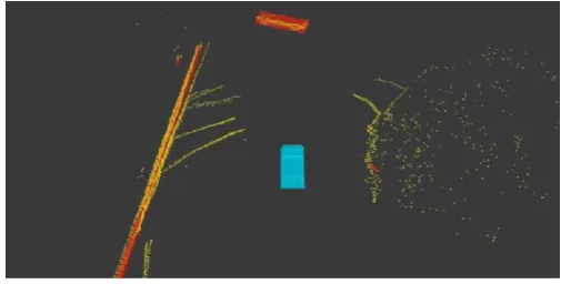
Depending on the test scenario the level of perception required can vary and involves processes such as data filtering, sensor data fusion, object classification etc. to generate the necessary knowledge of the vehicle location and its surroundings. It is also limited to the sensor suite on the vehicle as different sensors such as camera, LIDAR, RADAR etc. have their own advantages and limitations, and very often a combination of them all is required to generate the necessary coverage and confidence of the perceived environment. The perception system implemented for the Tata ACE vehicle involved ‘localisation’ through the use of a high precision GPS-IMU integrated system and the knowledge of the surrounding was built through the use of the IBEO Lidar system. The IBEO LIDAR system had inbuilt fusion and classification algorithms, which provided the processed surrounding information to the vehicle in the relative local coordinate system. PolySync core was used as a runtime and development infrastructure for the perception system which allowed for easy integration of the sensors information to form a world representation around the vehicle [12]. Fig 4 is a snapshot of the LIDAR sensor fusion output on the Tata ACE, with the ACE vehicle marked in blue and the obstacle when detected through point cloud and classified, are marked by red bounding boxes.
Fig. 4. The Lidar snapshot showing detection of obstacles using point cloud.
B. Motion Control Implementation
Motion control involves generating the necessary steering and acceleration-brake actuation commands for enabling the autonomous vehicle to follow a planned trajectory by the path planner. Therefore, the motion controller is tasked with controlling the vehicle's lateral and longitudinal motion[13]. The motion control implementation in our control software framework was designed through two separate but mutually influencing control functions, for lateral and longitudinal control of the vehicle. The lateral motion control function takes the vehicle trajectory as a reference and generates the real-time steering actuation commands to steer the front wheels of the vehicle using the vehicle current position and wheel angle feedback. The longitudinal motion control function takes the vehicle speed demand from the reference trajectory and generates in real-time the acceleration and brake actuation commands using the vehicle measured speed feedback. A well designed and tuned PID control technique was used in this work for both the lateral and longitudinal control functions. The
[image:3.595.38.290.641.728.2]capability of the two functions was tuned to the acceptable level of performance through back-to-back vehicle tests.
C. Path Planning Implementation
[image:4.595.341.526.129.219.2]A three-level hierarchical path planning framework was developed to facilitate the development of an adaptive control capability for the autonomous vehicle. Fig 5 describes the schematic of the path planning scheme with its three planner functions.
Fig. 5. Hierarchical Path Planning function block diagram.
The global planner is the first of the three planners and is designed with the objective of planning a global path for the autonomous vehicle connecting its present location to the final desired destination[14]. The global path which is generated in the form of sparsely separated waypoints forms the reference path for the vehicle to follow. This path is then used by the behaviour planner and the local planner to be able to continuously generate motion trajectories in real-time to arrive at the desired final destination. The algorithm flow for the global path planner is described through a pseudo-code shown in Table I, where the subject vehicle is the autonomous vehicle.
TABLE I. THE PSEUDOCODE FOR GLOBALPATHPLANNER.
While (subject vehicle has not reached its final destination)
1. Determine the set of global position nodes that connect to form an optimal path according to the selected objective (shortest travel time, shortest travel distance, maximum fuel economy).
2. Generate a discretised path waypoint for the optimal set of nodes to form a global path output.
In the current implementation only a single path was chosen, therefore only the second part of the global path planning function was used.
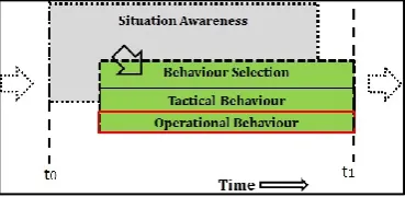
The second type of planner in the path planning solution is the behaviour planner, which is designed to generate high-level vehicle behaviours using the global path as a reference and with the information gathered by the perception system. The planner functions are modelled using the methodology described in our previous publication [1]. In the current implementation, the behaviour prediction function is not included and therefore it this work assumes that the behaviours of the other actors as predictable. Fig 6 describes the planning time slice, at each iteration of the behaviour planner execution. The behaviour planner consists of a tactical behaviour decision function for deliberative decision making and an operational behaviour
function for reactive decision making. The planner selects the appropriate motion behaviours with the knowledge of its surroundings through its Situation Awareness (SA) function.
Fig. 6. Behaviour Planner information flow time slice.
The developed behaviour planner can plan behaviours within the sensor range of the vehicle. In the current implementation, this range was limited to 50m in the ACE vehicle, which subsequently limited the top speed of the vehicle to 20kph. This sensor range, and hence the vehicle top speed will be improved in future trials. The algorithm flow for the behaviour planner is shown in Table II.
TABLE II. THE PSEUDOCODE FOR BEHAVIOUR PLANNER.
While (subject vehicle has not reached its final destination)
1. Determine the actors of interest in the scene (Situational Awareness).
2. Predict the behaviour of the actors of interest (Behaviour Prediction).
3. Select the tactical (follow-on / stop) and operational (accelerate/decelerate/cruise) behaviours for the vehicle.
The current implementation had limited tactical behaviour implementation, which was sufficient for the scenario used for testing. Further behaviours modes such as overtaking, merging etc. will be added to give the planner capability to handle other real world scenarios.
The third and the final planner in the path planning solution is the local path planner. The local planner is designed with the objective to generate traversable, obstacle free, look-ahead trajectories in real-time[15]. To enable the generation of the look-ahead trajectory, the local planner uses the information of the environment such as the road boundaries, the curvature of the road, the speed limits and information of obstacles within the vicinity of the subject vehicle. The local planner uses the selected tactical and operational behaviours by the behaviour planner to generates a generate the motion trajectory. The algorithm flow for the local path planner is shown in Table III
TABLE III. THE PSEUDOCODE FOR LOCAL PLANNER.
While (subject vehicle has not reached its final destination)
1. Determine the trajectory length using the vehicle current speed.
2. Create candidate trajectories for the vehicle to follow global waypoints and the selected vehicle behaviours from the current vehicle position.
[image:4.595.42.285.194.308.2]III. SIMULATIONANDEXPERIMENTALRESULTS This section is split into two parts, with the first part describing the simulation set-up and testing of the path planning and motion control algorithms in a virtual environment, and the second part covers the real world testing on the vehicle platform Tata ACE.
A. Algorithm Testing in Simulation
[image:5.595.314.550.227.415.2]The path planning and motion control algorithms described in section II were programmed in Matlab Simulink and tested in a simulation platform called PreScan. PreScan is an environmental modelling software that enables generation of artificial test scenarios for testing of ADAS and autonomous vehicle control algorithms [16]. The building a test scenario in PreScan is illustrated through a 4-step process in Fig 7.
Fig. 7. The development process of Virtual Testing Environment.
PreScan allows for the integration of custom developed control systems, and also allows for integrating vehicle dynamic plant model through its Matlab Simulink environment. Fig 8 describes the integration of the control software (path planning and motion control algorithms) and vehicle dynamic plant model in PreScan.
Fig. 8. Simulation set-up of autonomous vehicle software testing in PreScan.
In this work the vehicle plant model of Tata Ace Electric vehicle was built within Matlab Simulink and using the data collected from on-road testing, the model parameters were tuned to generate dynamic responses that represented the real
[image:5.595.50.276.262.434.2]vehicle. This model allowed the vehicle responses to be simulated in the virtual environment and therefore allow initial testing of the algorithms in a safe setting. A virtual test scenario was built in PreScan consisting of straight sections of the road and three roundabouts as shown in Fig 9 (a). A scenario with roundabouts was chosen as it represented a good test case for evaluating both vehicles lateral and longitudinal motion performance. The path planning output is depicted in Fig 9 (b), where the global path is described by the major plot and the local path planning which involves generating the trajectories and selecting the best trajectory is shown in the enlarged section of Fig 9(b).
Fig. 9. (a) Picture of the test scenario, (b) The path planning output from the of Global Path Planner and the Local Path Planner [enlarged]
The behaviour planner selected the tactical and operational behaviours for the motion of the subject vehicle. Fig 10 describes the time series mapping of the behaviour plans.
Fig. 10.Behaviour planner request mapping for the selected scenario.
The virtual test scenario was built without any moving actors, which meant the tactical behaviour planner demanded the “follow-on” behaviour for most of the travel distance until the autonomous vehicle approached its final destination. The
[image:5.595.307.562.495.665.2] [image:5.595.38.294.541.674.2]operational behaviour showed a consistent shift of operation behaviour modes, depending on the road layout and the existing scenarios conditions. When approaching the three roundabouts the operation behaviour demanded the vehicle to slow its speed due to the impending high curvature road layout, it also demanded the vehicle cursing behaviour when travelling within the three roundabout and finally it accelerated to achieve the desired road speed by demanding acceleration mode in the straight sections of the road.
The autonomous vehicle motion control performance was evaluated in simulation by comparing the vehicle lateral and longitudinal command to the response from the vehicle model. Fig 11 shows a close matching of the vehicle speed response which was used to qualify the vehicle longitudinal motion control performance and the steer angle response which validates the vehicle lateral motion control performance.
Fig. 11.Vehicle Lateral and Longitudinal control perfomance.
B. Algorithm Testing in the Vehicle.
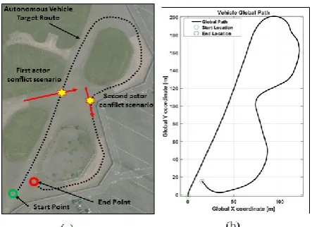
[image:6.595.323.545.81.242.2]After having tested the control framework in a virtual environment, the algorithms were then auto-coded into a real-time controller platform, Speedgoat. The controller was then used on the Tata ACE vehicle, which was equipped with the necessary calibrated sensing units. The test scenario used for the real-world testing is shown in Fig 12(a), which describes the vehicle going around two bends which had two crossroads intersections. In the real-world test, a human driven vehicle was used as a moving actor in the scene, and two crossroad intersection scenarios were emulated to check the vehicle tactical and operational behaviour performance. The Global path planning was carried out in Cartesian coordinate system, and the global position converted to patrician using the Universal Transverse Mercator system. For dealing with smaller coordinate numbers the vehicle starting point was used as the global zero reference. Fig 12(b) describes the creation of the global path plan for the autonomous Tata ACE vehicle in the current test scenario.
Fig. 12.(a) Annotated google map extract of the real-world test scenario, (b) Global Path plan for the Autonomous ACE vehicle.
[image:6.595.37.292.287.484.2]The situation awareness function of the behaviour planner evaluates the vehicle surroundings for determining the surrounding obstacle criticality and conflict with the subject vehicle motion path. The situation awareness function of the behaviour planner module generated a flag to indicate when the moving obstacle (human-driven vehicle) was in conflict with the vehicle path. This phenomenon is described by in Fig 13.
Fig. 13.Situation Awareness function output for behaviour planning.
The behaviour planner then generated the tactical and operational behaviours plans for the given scenario, which are described through a time series plot shown in Fig14. The behaviour planner output shows consistent behaviour planning by both the tactical and operational behaviour planning functions for the existing scenario. The tactical behaviour planning function demanded the vehicle to stop twice on the planned global path when the situation awareness function estimated that the motion of the other actor in the scene was in conflict with the host vehicle motion path. The operational behaviour responded according to the chosen tactical plan to decelerate to a safe stop.
[image:6.595.307.559.366.526.2]Fig. 14.Behaviour Plans for the Real-world Test Scenario.
[image:7.595.35.319.362.716.2]The autonomous motion control performance in real-world tests was then evaluated by comparing the controller lateral and longitudinal control command with the vehicle response as shown in Fig 15 and Fig 16 respectively.
Fig. 15.Tata ACE vehicle Lateral Motion Control Perfomance.
Fig. 16.Tata ACE vehicle Longitudinal Motion Control Perfomance.
The errors in the steering response and the speed response highlighted the need to improve the current implementation of the motion controller. However, the current performance did suffice to test the hybrid control software framework which was the prime focus of this study.
IV. CONCLUSION
In this paper, we described the design, implementation and testing of a modular hybrid autonomous vehicle control software framework, which is capable of deliberative and reactive planning. This development of the control framework involved the integration of the perception, path planning and motion control algorithms that were implemented in Matlab Simulink. The control software framework was then validated by first testing in a virtual testing environment-PreScan, by building an artificial test scenario. The simulation set-up developed in this work gives a robust testing environment for testing the algorithms in safe virtual setting, which also reduced the time required for real-world tests. Once the performance of the planning and motion control algorithms were deemed to be satisfactory, they were then auto-coded on the vehicle real-time controller for real-world testing. The resulting performance evaluation in both simulation and real-world testing showed the acceptable level of performance while also highlighting the areas of improvement.
Crucially the control software framework is designed with the aim of it being scalable to accommodate future development of the behaviour planner algorithms. The next phase of the development is to develop, integrate and tests adaptive tactical behaviour planner described in [1], within the control software framework.
REFERENCES
[1] M. Rodrigues, A. McGordon, G. Gest, and J. Marco, “Adaptive tactical behaviour planner for autonomous ground vehicle,” in 2016
UKACC 11th International Conference on Control (CONTROL),
2016, pp. 1–8.
[2] U. Chris, A. Joshua, B. Drew, B. Christopher, B. Robert, N. C. M, D. John, D. Dave, G. Tugrul, G. Chris, G. Michele, H. Sam, H. Martial, M. H. Thomas, K. Sascha, K. Alonzo, L. Maxim, and F. Dave, “Autonomous Driving in Urban Environments: Boss and the Urban Challenge,” IFAC Proc. Vol., vol. 7, no. February, pp. 81–86, 2007. [3] M. Montemerlo, J. Becker, S. Bhat, H. Dahlkamp, D. Dolgov, S.
Ettinger, D. Haehnel, T. Hilden, G. Hoffmann, B. Huhnke, D. Johnston, S. Klumpp, D. Langer, A. Levandowski, J. Levinson, J. Marcil, D. Orenstein, J. Paefgen, I. Penny, A. Petrovskaya, M. Pflueger, G. Stanek, D. Stavens, A. Vogt, and S. Thrun, “Junior: The stanford entry in the urban challenge,” Springer Tracts Adv. Robot., vol. 56, no. October 2005, pp. 91–123, 2009.
[4] J. Bohren, T. Foote, J. Keller, A. Kushleyev, D. Lee, A. Stewart, P. Vernaza, J. Derenick, J. Spletzer, and B. Satterfield, “Little Ben: The Ben Franklin Racing Team’s entry in the 2007 DARPA Urban Challenge,” Springer Tracts Adv. Robot., vol. 56, pp. 231–255, 2009. [5] C. Reinholtz, D. Hong, A. Wicks, A. Bacha, C. Bauman, R. Faruque, M. Fleming, C. Terwelp, T. Alberi, D. Anderson, S. Cacciola, P. Currier, A. Dalton, J. Farmer, J. Hurdus, S. Kimmel, P. King, A. Taylor, D. Van Covern, and M. Webster, “Odin: Team VictorTango’s entry in the DARPA Urban Challenge,” J. F. Robot., vol. 25, pp. 125– 162, 2008.
[6] S¨. Kammel, J. Ziegler, B. Pitzer, T. Gindele, D. Jagzent, J. Schr, and F. Von Hundelshausen, “Team AnnieWAY’s Autonomous System for the DARPA Urban Challenge 2007,” J. F. Robot., vol. 25, pp.
360–391, 2008.
[7] J. Ziegler, T. Dang, U. Franke, H. Lategahn, P. Bender, M. Schreiber, T. Strauss, N. Appenrodt, C. G. Keller, E. Kaus, C. Stiller, and R. G. Herrtwich, “Making Bertha Drive — An Autonomous Journey on a Historic Route,” vol. 6, no. 2, pp. 8–20, 2014.
[8] A. Broggi, P. Medici, P. Zani, A. Coati, and M. Panciroli, “Autonomous vehicles control in the VisLab Intercontinental Autonomous Challenge,” Annu. Rev. Control, vol. 36, no. 1, pp. 161– 171, 2012.
[9] A. Broggi, P. Cerri, S. Debattisti, M. C. Laghi, P. Medici, M. Panciroli, and A. Prioletti, “PROUD-public road urban driverless test: Architecture and results,” IEEE Intell. Veh. Symp. Proc., no. Iv, pp. 648–654, 2014.
[10] Google, “Google Self-Driving Car Project,” 2015.
[11] B. Martin, I. Karl, and S. Sanjiv, The DARPA Urban Challenge.
2009.
[12] J. J. Hartung, J. Lamb, D. P. Miller, and R. D. Hambrick, “Autonomous Vehicle Interface System.” Google Patents, 2015. [13] A. Khodayari, A. Ghaffari, S. Ameli, and J. Flahatgar, “A Historical
Review on Lateral and Longitudinal Control of Autonomous Vehicle Motions,” no. Icmet, 2010.
[14] S. Kolski, D. Fergusont, M. Bellino, and R. Siegwart, “Autonomous Driving in Structured Unstructured Environments,” in Intelligent
Vehicle Symposium, 2006, pp. 558–563.
[15] X. Li, Z. Sun, D. Liu, Q. Zhu, and Z. Huang, “Combining Local Trajectory Planning and Tracking Control for Autonomous Ground Vehicles Navigating along a Reference Path,” 2014.
![Fig. 1. Hybrid Autonomous Vehicle Control Software Framework[1].](https://thumb-us.123doks.com/thumbv2/123dok_us/9451621.452364/2.595.307.559.539.666/fig-hybrid-autonomous-vehicle-control-software-framework.webp)
![Fig. 9. (a) Picture of the test scenario, (b) The path planning output from the of Global Path Planner and the Local Path Planner [enlarged]](https://thumb-us.123doks.com/thumbv2/123dok_us/9451621.452364/5.595.38.294.541.674/picture-scenario-planning-output-global-planner-planner-enlarged.webp)