warwick.ac.uk/lib-publications
Original citation:
Lan, Rong, Cowin, Peter I., Sengodan, Sivaprakash and Tao, Shanwen. (2016) A perovskite
oxide with high conductivities in both air and reducing atmosphere for use as electrode for
solid oxide fuel cells. Scientific Reports, 6. 31839.
Permanent WRAP URL:
http://wrap.warwick.ac.uk/81328
Copyright and reuse:
The Warwick Research Archive Portal (WRAP) makes this work of researchers of the
University of Warwick available open access under the following conditions.
This article is made available under the Creative Commons Attribution 4.0 International
license (CC BY 4.0) and may be reused according to the conditions of the license. For more
details see:
http://creativecommons.org/licenses/by/4.0/
A note on versions:
The version presented in WRAP is the published version, or, version of record, and may be
cited as it appears here.
www.nature.com/scientificreports
A perovskite oxide with high
conductivities in both air and
reducing atmosphere for use as
electrode for solid oxide fuel cells
Rong Lan
1, Peter I. Cowin
2, Sivaprakash Sengodan
1& Shanwen Tao
1,3Electrode materials which exhibit high conductivities in both oxidising and reducing atmospheres are in high demand for solid oxide fuel cells (SOFCs) and solid oxide electrolytic cells (SOECs). In this paper, we investigated Cu-doped SrFe0.9Nb0.1O3−δ finding that the primitive perovskite oxide SrFe0.8Cu0.1Nb0.1O3−δ
(SFCN) exhibits a conductivity of 63 Scm−1and 60 Scm−1 at 415 °C in air and 5%H2/Ar respectively. It is believed that the high conductivity in 5%H2/Ar is related to the exsolved Fe (or FeCu alloy) on exposure to a reducing atmosphere. To the best of our knowledge, the conductivity of SrFe0.8Cu0.1Nb0.1O3−δ in a reducing atmosphere is the highest of all reported oxides which also exhibit a high conductivity in air. Fuel cell performance using SrFe0.8Cu0.1Nb0.1O3−δ as the anode, (Y2O3)0.08(ZrO2)0.92 as the electrolyte and
La0.8Sr0.2FeO3−δ as the cathode achieved a power density of 423 mWcm−2 at 700 °C indicating that SFCN is a promising anode for SOFCs.
Solid oxide fuel cells (SOFCs) are electrochemical devices used to convert chemical energy into electricity with a very high efficiency1. Symmetrical fuel cells have the potential application to be used as reversible SOFCs, which
can operate in both fuel cell and electrolyser modes. In a recent report, it was found that a much better stability can be achieved by SOFCs which operate in both SOFC and solid oxide electrolytic cell (SOEC) modes (reversible SOFC)2. For reversible SOFCs, the use of a symmetrical electrode such as (La
0.75Sr0.25)Cr0.5Mn0.5O3−δ (LSCM)
would be an ideal solution3–5. An essential requirement of the electrode material is that it must exhibit a high
conductivity in both air and fuel conditions at the fuel cell operating temperature. Therefore, electrode materials exhibiting high conductivities in both oxidising and reducing atmospheres are in high demand for solid oxide fuel cells (SOFCs) and solid oxide electrolytic cells (SOECs), particularly for symmetrical SOFCs.
There are plenty oxide materials which exhibit high conductivity in air. The real challenge is to identify a good stable oxide anode material exhibiting high conductivity in a reducing atmosphere5,6. Several redox stable mixed
oxide-ion electronic conductors have been developed as ceramic anode materials for SOFCs, such as (La0.75Sr0.25)
Cr0.5Mn0.5O3−δ (LSCM)7, Sr2MgMoO6−δ (SMMO)8, La4Sr8Ti11Mn0.5Ga0.5O37.5 (LSTMG)9, La0.8Sr0.2Sc0.2Mn0.8O3−δ
(LSSM)10, La
0.7Ca0.3CrO3−δ11, Sr2Fe1.5Mo0.5O6−δ12,13; Pr0.8Sr1.2(Co,Fe)0.8Nb0.2O4+δ/CoFe alloy14, PrBaMn2O5+δ15,
La0.33Sr0.67Ti0.33Mn0.67O3−δ (LSTM)16, Ce0.6MN0.3Fe0.1O2-La0.6Sr0.4Fe0.9Mn0.1O3 (CMF-LSFM)17. All of these oxides
or composite anodes are redox stable or redox reversible. However, except for La-doped SrTiO3, the conductivity
at the anode is typically below 30 S/cm. The anode conductivity needs to be further improved, particularly for tubular SOFCs with a long pathway for electrons. The conductivity of La-doped SrTiO3 in a reducing
atmos-phere is high if pre-reduced at a high temperature. However, the conductivity of doped SrTiO3 in air is generally
less than 0.1 S/cm6,9,18. In reported perovskite oxides, besides LSCM, The double perovskite Sr
2Fe1.5Mo0.5O6−δ
(SFMO), was demonstrated to be a good electrode for symmetrical SOFCs12,13. However, the conductivity of
SFMO under the SOFC anode environment is not very high thus further improvements are required13. On the
other hand, a promising family of redox stable anodes for SOFCs is B-site doped SrFeO3−δ. It has been reported
that SrFe1-xTixO3−δ where x = 0.3, 0.4 combined with Ce0.9Gd0.1O2−δ performs well as an anode for SOFCs19. It was
found that SrFe0.9Ti0.1O3−δ is redox stable with a conductivity of 2.53 S/cm at 600 °C in a reducing atmosphere20.
1School of Engineering, University of Warwick, Coventry CV4 7AL, UK. 2Department of Chemical and Process Engineering, University of Strathclyde, Glasgow G1 1XJ, UK. 3Department of Chemical Engineering, Monash University, Clayton, Victoria 3800, Australia. Correspondence and requests for materials should be addressed to S.T. (email: [email protected])
received: 20 April 2016 Accepted: 26 July 2016
www.nature.com/scientificreports/
Anikina et al. investigated the conductivity of SrFe1−xNbxO3−δ, where x = 0.05, 0.1, 0.2, 0.3, 0.4 and it was found
SrFe0.9Nb0.1O3−δ exhibits the highest conductivity in a reducing atmosphere. However, the conductivity is still
below 1 S/cm at temperatures below 800 °C21. In this study, we re-investigated the conductivity of SrFe
0.9Nb0.1O3−δ
finding that its conductivity in a reducing atmosphere was ~30 S/cm which is much higher than the reported values. It was also found that partial replacement of Fe by Cu in SrFe0.9Nb0.1O3−δ can further increase the
con-ductivity in a reducing atmosphere. The perovskite oxide SrFe0.8Cu0.1Nb0.1O3−δ (SFCN) exhibits a conductivity of
63 Scm−1 and 60 Scm−1 at 415 °C in air and 5%H
2/Ar respectively. To the best of our knowledge, the conductivity
of SrFe0.8Cu0.1Nb0.1O3−δ in a reducing atmosphere is the highest among reported oxide anodes for SOFCs which
also exhibit a high conductivity in air. A SOFC using SrFe0.8Cu0.1Nb0.1O3−δ as the anode and La0.8Sr0.2FeO3−δ as
the cathode has been fabricated with a good performance in hydrogen achieved at temperatures below 700 °C.
Structure of New Oxides SrFe
0.9−xCu
xNb
0.1O
3−δ(x =
0–0.4)
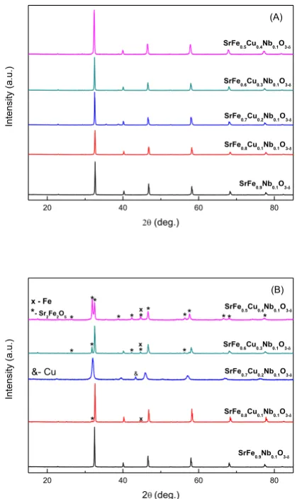
X-ray diffraction of SrFe0.9−xCuxNb0.1O3−δ (x = 0–0.4) showed that it exhibited a single phase cubic perovskite
structure (SG: Pm-3m) for all compounds (Figure S1). The XRD pattern of the SrFe0.8Cu0.1Nb0.1O3−δ sample is
shown in Fig. 1A. The increase in the copper content significantly reduced the sintering temperature of the mate-rial, with the formation of a single phase perovskite structure that was not observed for SrFe0.4Cu0.5Nb0.1O3−δ.
Reitveld refinement of the structure using GSAS22 demonstrated a pseudo-linear increase in the lattice
param-eters with increased copper doping up to SrFe0.6Cu0.3Nb0.1O3−δ (Figure S3 and Table S2). The increase in lattice
parameters with increasing copper content can be attributed to the larger ionic radius of copper compared to iron (Cu2+0.73 Å, Fe3+0.645 Å, Fe4+0.585 Å)23. Samples SrFe
0.6Cu0.3Nb0.1O3−δ and SrFe0.5Cu0.4Nb0.1O3−δ exhibit similar
lattice parameters whilst no impurity peaks can be observed on the XRD patterns, this is thought to be due to the proximity of the solid solution limit. Therefore the limit for achieving single phase in the SrFe0.9−xCuxNb0.1O3−δ
series lies at x ≤ 0.5. The SEM picture of SrFe0.8Cu0.1Nb0.1O3−δ prepared by the solid state reaction method is
shown in Fig. 2A.
Thermogravimetric analysis of SrFe0.9−xCuxNb0.1O3−δ (x = 0–0.4) in air showed a minor total loss in weight for all
[image:3.595.152.362.43.396.2]compounds, between 0.2 wt% and 0.5 wt%, with no observable trend on increasing the dopant level, (Figure S3A). Accelerated weight loss was observed for all compounds on heating between 500 and 800 °C, with the weight loss noted to be reversible upon cooling. This acceleration in weight loss is likely to be the result of oxygen loss
Figure 1. Room temperature X-ray diffraction patterns of SrFe0.9−xCuxNb0.1O3−δ (x = 0–0.4) (x = 0–0.4) after
www.nature.com/scientificreports/
through high temperature reduction. Differential scanning calorimetry, Figure S3B, exhibits a reversible transi-tion for all copper doped compounds, between 600 °C and 670 °C on heating and between 670 °C and 590 °C on cooling which could be related to high temperature phase transition24.
Conductivity of New Oxides SrFe
0.9−xCu
xNb
0.1O
3−δ(x =
0–0.4) in Air
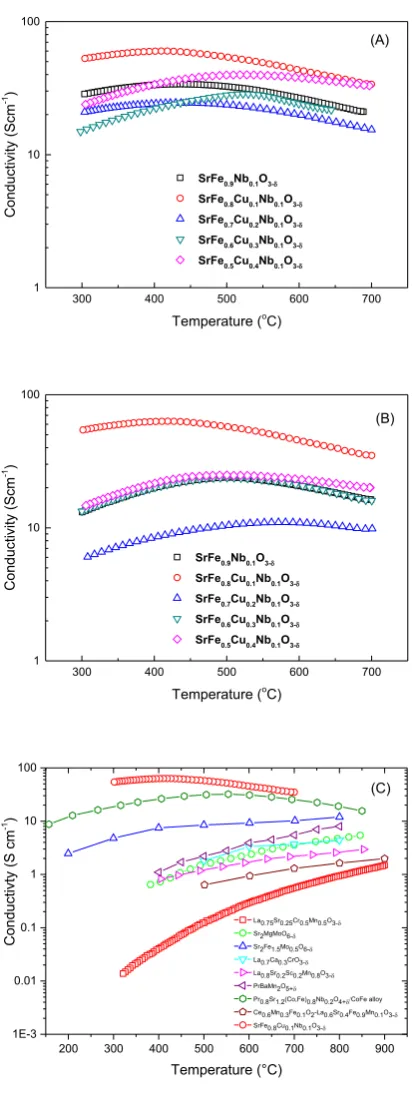
The conductivity of the electrode materials is a key parameter to consider when evaluating their use in SOFCs. Whilst minimal copper doping, forming SrFe0.8Cu0.1Nb0.1O3−δ, elicits a significant increase in conductivity in air
over SrFe0.9Nb0.1O3−δ, additional copper doping is observed to reduce the conductivity of the materials, although
increasing dopant levels do not elicit a linear response in the reduction in conductivity (Fig. 3A). The intro-duction of Cu2+ dopant is expected to increase the average charge of iron in the sample with the proportion of
Fe4+ ions, increasing the number of charge carriers and thus, in theory, increasing the conductivity25. Assuming
that the copper dopant does not directly contribute to electronic conduction, the increase in the charge carrier concentration is only proportional to the iron content of the compound, which reduces with increasing Cu2+
dopant concentration. Thus at higher Cu2+ dopant concentrations the increase in charge carriers through the
average charge of iron increasing is outweighed by the reduction in charge carriers through the reduction of the iron content leading to reduced conductivity. On the conductivity curves, a semiconductor-metal transition was observed for all compounds, with an increase in the transition temperature noted with increasing copper dopant levels (Fig. 3A). This transition has been observed previously for strontium ferrites, with Poulsen et al.26
suggesting that compound reduction at high temperature, resulting in a reduction in the charge carriers, was the cause of the transition. A pseudo-linear reduction in the oxygen content of strontium ferrite in air above 400 °C with increasing temperature, which would appear to confirm compound reduction at these temperatures, was observed previously27. The increase in the conductivity with increasing temperature was determined by Patrakeev et al. to be offset by the reduction in charge carrier concentration, causing an overall reduction in the electronic conductivity with increasing temperature, resulting in the pseudo-metallic behaviour28.
Stability of New Oxides SrFe
0.9−xCu
xNb
0.1O
3−δ(x =
0–0.4)
In order to investigate the stability of SrFe0.9−xCuxNb0.1O3−δ (x = 0–0.4) in a reducing atmosphere, STA analyses
in 5%H2/Ar was carried out on the samples. The observed weight loss upon reduction of SrFe0.9−xCuxNb0.1O3−δ
(x = 0–0.4) varies between 2.6% and 3.3%, with no observed trend with increasing dopant concentration (Figure S4A). Differential scanning calorimetry exhibits non-reversible transitions on heating for all compounds between 600 °C and 670 °C, associated with cationic reduction (Figure S4B)20. With the increase of copper dopant, the
exo-thermic peaks happened at lower temperature indicating the reduction at lower temperature thus they are likely less stable, this has been confirmed by the XRD study (Fig. 1B). After reducing in 5%H2/Ar at 700 °C for 10 hours,
it was found that the Cu-free sample SrFe0.9Nb0.1O3−δ was redox stable. For sample SrFe0.8Cu0.1Nb0.1O3−δ, the
majority of the phase is perovskite whilst an extra peak at ~45 degree was observed which belongs to the strongest (110) peak of α -Fe (PDF: 6–696) after the reduction at 700 °C29. The formation of a Fe-rich FeCu alloy cannot be
ruled out but the Cu content must be very low otherwise the peak should shift to a higher d-spacing. The exso-lution of metal particles is further confirmed by SEM observation where a small particle of iron was exsolved on the surface after the reduction (Fig. 2B). The very weak peak at ~32.5° could be a peak for a solid solution based on Sr2Fe2O5+δ parent phase30. When x is increased to 0.2, the majority of sample SrFe0.7Cu0.2Nb0.1O3−δ is
[image:4.595.160.475.47.253.2]possibly Sr2Fe2O5+δ solid solution while an extra peak at ~43° was observed which could be the strongest peak
Figure 2. SEM pictures of sample SrFe0.8Cu0.1Nb0.1O3−δ powders after obtained in air (A); after further
reduction in 5%H2/Ar at 700 °C for 10 hours (B); after further xoidise in air at 1300 °C for 15 hours then reduce
at 700 °C in 5%H2/Ar for 10 hours (3 cycles with final step of reoxidation) (C) and futher reduction in 5%H2/Ar
www.nature.com/scientificreports/
of Cu (Fm-3m)31. Again, formation of a Cu-rich FeCu alloy is also possible with the presence of Fe at the B-site
of the perovskite phase. At x = 0.3, 0.4, Sr2Fe2O5+δ based solid solution is the major phase with the Fe or Fe-rich
alloy also present. The exsolution of metal seems strongly related to the composition, which will require further investigation. To exam whether the exsolution of metal is reversible, the reduced SrFe0.8Cu0.1Nb0.1O3−δ sample was
re-oxidised in air at 1300 °C for 15 hours then further reducing in 5%H2/Ar at 700 °C for 10 hours and stop at the
re-oxidation stage after 3 cycles. It was observed that the exsolved metal was ‘adsorbed’ back after re-oxidation ii air at high temperature (Fig. 2C) while it was exsolved out after further reduction in 5%H2/Ar at 700 °C for
[image:5.595.155.363.38.590.2]10 hours (Fig. 2D). This indicate the process for exsolved metal is reversible as observed in other oxides32,33.
Figure 3. Conductivity of SrFe0.9−xCuxNb0.1O3−δ (x = 0–0.4) in air (A) 5% H2/Ar (B) and comparison of
www.nature.com/scientificreports/
Conductivity of New Oxides SrFe
0.9−xCu
xNb
0.1O
3−δ(x =
0–0.4) in 5%H
2/Ar
To measure the conductivity in a reducing atmosphere, the SrFe0.9−xCuxNb0.1O3−δ pellets were coated with
sil-ver electrodes on both sides then reduced in 5%H2/Ar at 700 °C for 10 hours (Fig. 3B). The conductivity was
measured in 5%H2/Ar on cooling. The highest conductivity for the samples measured was found to be for the
SrFe0.8Cu0.1Nb0.1O3−δ sample with a conductivity of about 30–60 S/cm, in a reduced atmosphere. This is
pos-sibly due to the presence of exsolved Fe particles leading to increased electronic conductivity thus the total conductivity was also high. The lowest conductivity was observed for sample SrFe0.7Cu0.2Nb0.1O3−δ, due to the
Sr2Fe2O5+δ based solid solution being the major phase. This indicates that the conductivity of Sr2Fe2O5+δ based
solid solution is lower than the primitive perovskite oxide based on SrFeO3−δ. When x increased to 0.3 and 0.4,
the intensity of the peak at ~45 ° which represents the exsolved Fe is obviously stronger than that for sample SrFe0.8Cu0.1Nb0.1O3−δ (Fig. 1B) even though the major phase was the Sr2Fe2O5+δ based solid solution. The
conduc-tivity of SrFe0.6Cu0.3Nb0.1O3−δ is comparable to that for the Cu-free sample SrFe0.9Nb0.1O3−δ whilst the conductivity
of sample SrFe0.5Cu0.4Nb0.1O3−δ is slightly higher (Fig. 3B) due to higher concentration of exsolved Fe (or Fe-rich
alloy). In the investigated oxides, in terms of both redox stability and conductivity, sample SrFe0.8Cu0.1Nb0.1O3−δ
is the best.
For comparison, the conductivity of sample SrFe0.8Cu0.1Nb0.1O3−δ in a reducing atmosphere is plotted together
with the reported best oxide anodes for SOFCs (Fig. 3C). It is the highest among the reported materials with rea-sonably high conductivity in air and a conductivity two times greater than that of the Pr0.8Sr1.2(Co,Fe)0.8Nb0.2O4+δ/
CoFe alloy14. The conductivities of all other reported oxide anode materials in a reducing atmosphere are lower
than 30 S/cm. This is clearly shown when the conductivity is plotted at absolute value (Figure S5). High conductiv-ity is very important for SOFCs due to some designs involving long pathways for electrons at the electrode. Both SFCN and Pr0.8Sr1.2(Co,Fe)0.8Nb0.2O4+δ/CoFe alloy have exsolved metal under reduction indicating that designing
a material with exsolved metal under reduction will help to achieve a high conductivity in a reducing atmosphere. The exsolved metal may also improve the catalytic activity under the fuel cell operating conditions34,35.
Fuel Cell Performance when SrFe
0.8Cu
0.1Nb
0.1O
3−δWas Used as the Anode
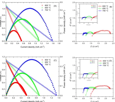
Solid oxide fuel cells with a SrFe0.8Cu0.1Nb0.1O3−δ anode, YSZ electrolyte and La0.8Sr0.2FeO3−δ cathode were
fab-ricated. The performance and the corresponding A.C. impedance spectra of hydrogen/air fuel cell at different temperatures are shown in Fig. 4A,B. Good fuel cell performance with a power density of 423 mW/cm2 was
observed at 700 °C. The total polarisation resistance of the electrode at 700 °C was only 0.25 Ω cm2 indicating
SrFe0.8Cu0.1Nb0.1O3−δ performs well as an anode for SOFCs. However, a small amount of Ru/CeO2 was
intro-duced to improve the catalytic activity. For comparison, a SOFC with the same electrolyte and cathode was assembled with the Cu-free anode SrFe0.9Nb0.1O3−δ used instead of the Cu doped anode. As shown in Fig. 4C,D,
the highest power density at 700 °C was 372 mW/cm2 which was slightly lower than that for a SOFC with
SrFe0.8Cu0.1Nb0.1O3−δ anode. The total electrode polarisation was 0.30 Ω cm2 at 700 °C. The series resistance was
0.54 Ω cm2 which is also slightly higher than that of the cell where the SrFe
0.8Cu0.1Nb0.1O3−δ anode was used
(0.50 Ω cm2) (Fig. 4B,D). This indicates that the high conductivity of SrFe
0.8Cu0.1Nb0.1O3−δ reduces both series and
electrode polarisation resistances leading to high fuel cell performance. It should be noted that the exsolved Fe (or Fe rich FeCu alloy) at the SrFe0.8Cu0.1Nb0.1O3−δ anode may also improve the anode catalytic activity resulting
in lower electrode polarisation resistance. The Arrhenius plot area-specific resistances (ASRs) for non-ohmic resistance of SrFe0.9Nb0.1O3−δ and SrFe0.8Cu0.1Nb0.1O3−δ anodes are shown in Figure S6. At 600 °C, the ASR for the
two oxide anodes are similar but the ASR for SrFe0.8Cu0.1Nb0.1O3−δ is much lower at 650 and 700 °C indicating
better catalytic activity. Copper, copper alloy and iron alloy has been widely studied as excellent anode catalysts in SOFCs6,36–39. In an early reported, it was found that FeCo alloy was exsolved from Pr
0.4Sr0.6Co0.2Fe0.7Nb0.1O3−δ
anode while excellent fuel cell performance has been achieved although the conductivity of this material was not presented40.
Conclusions
In this work, a conductive perovskite oxide SrFe0.8Cu0.1Nb0.1O3−δ has been identified which exhibits the highest
conductivity in a reducing atmosphere for oxides which also exhibit a high conductivity in air. This high conduc-tivity is probably related to the exsolution of Fe (or Fe-rich FeCu alloy) during the high temperature reducing pro-cess. After the reduction, besides the exsolved metal, the major phase is that of the perovskite. Good performance at intermediate temperatures in solid oxide fuel cells using the SrFe0.8Cu0.1Nb0.1O3−δ based anode indicates that
it is a promising anode for SOFCs. This study indicates that the conductivity of the oxides with exsolved metal is significantly high. This provides a strategy to identify a good material with high conductivity in both air and reducing atmospheres, i.e., starting from an oxide material with high conductivity in air, followed by introduc-ing transition elements such as Fe, Co, Ni, Cu in the lattice which may be exsolved from the lattice on reduction therefore resulting in high conductivity in a reducing atmosphere.
Methods
Synthesis of oxides.
SrFe0.9−xCuxNb0.1O3−δ (x = 0–0.4) were synthesised by a sol-gel process, similar topre-viously reported processes20. A stoichiometric amount of C
4H4NNbO9·xH2O (99.9%, Sigma Aldrich) was
dis-solved in distilled water. H2O2 was added to the niobium solution until a colour change was elicited. Citric acid
(99+%, Alfa Aesar), in a 2:1 molar ratio to the metal ions in the final product, was added and heated till a
solu-tion was formed. Stoichiometric amounts of Sr(NO3)2 (98%, Alfa Aesar), Fe(NO3)3·9H2O (98%, Alfa Aesar) and
Cu(NO3)2·2.5 H2O (ACS grade, Alfa Aesar) were dissolved in distilled water. The solutions were mixed first then
www.nature.com/scientificreports/
Analytical Procedures.
X-ray data was collected on a PANanalyticalX’Pert Pro in the Bragg-Brentano reflection geometry with a Ni-filtered Cu Kα source (1.5405 Å), fitted with a X’Celerator detector and an Empyrean CuLFF xrd tube. Absolute scans in the 2θ range of 5–100° with step sizes of 0.0167° were used during data collection. GSAS22 software was used to perform a least squares refinement of the lattice parameters of allthe samples.
Thermal analysis was conducted using a Stanton Redcroft STA 1500 Thermal Analyser on heating from room temperature to 800 °C and on cooling from 800 °C to room temperature in air, with a heating/cooling rate of 10 °C/min, and in 5% H2/Ar, again with a heating/cooling rate of 10 °C min−1, and with a flow rate of 5% H2/Ar
of 50 mLmin−1.
Scanning electron mircroscopy (SEM) measurements were carried out on a ZEISS SUPRA 55-VP Field Emission Scanning Electron Microscope. The densities of the pellets were determined from the measured mass and volume. Theoretical densities were calculated using experimental lattice parameters and the chemical for-mula SrFe0.9−xCuxNb0.1O3−δ (x = 0–0.4). The relative density of the pellets was 80–90% for all compounds.
Conductivity Testing.
The pellets (ø ≈ 13 mm × 2 mm) were coated on opposing sides using silver paste for all samples. The conductivity of the samples was measured primarily in air between 300 °C to 700 °C. Secondary measurements over the same temperature range were conducted in 5% H2/Ar following an equilibration step of10 hours at 700 °C in 5% H2/Ar. Measurements were conducted using a pseudo four-terminal DC method using a
SolartronCell 1470E electrochemical interface controlled by CellTest software with an applied current of 1 - 0.1 A.
[image:7.595.157.554.43.395.2]Fuel Cell Fabrication and Testing.
The electrolyte support cell used in this study was prepared through a tape casting process, with the outer two layers having pore formers. A dense YSZ slurry was prepared by mixing YSZ powder with methyl ethyl ketone and ethanol, and along with binders (polyvinyl butyral and polyethylene Glycol). Porous YSZ was prepared by adding YSZ powder with methyl ethyl ketone and ethanol, binders (pol-yvinyl butyral and polyethylene Glycol) and graphite (UCP-2 grade, Alfa Aesar) sequentially. The resultant two slurries were tape-casted separately. The porous–dense–porous YSZ structure was prepared by laminating three green tapes, followed by sintering at 1500 °C for 4 h, after which the porosity was approximately 65%. The final thicknesses of the dense electrolyte and porous electrode were ~100 μ m and 45 μ m, respectively. The diameter ofwww.nature.com/scientificreports/
the porous YSZ region was 0.67 cm. To prepare composites of SFN-YSZ and SFCuN-YSZ electrolyte supported cell, the precursor solutions were firstly prepared by dissolving nitrate salts of Sr, Fe, Cu, and Nb in distilled water with the addition of quantitative amounts of citric acid. The SFCuN -YSZ anode was prepared by infiltrating the precursor aqueous solution into the anode side of the three-layered YSZ backbone. SFCuN was infiltrated into then porous YSZ backbone by a multi-step process followed by heating at 450 °C to decompose nitrates and citric acid. The infiltration process was repeated until 40 wt% loading of the oxide was achieved. Finally, SFCuN-YSZ anode wafers were calcined in air at 1000 °C. The LSF (La0.8Sr0.2FeO3−δ)-YSZ cathode was fabricated by infiltration
using an aqueous solution of nitrate salts of La, Sr and Fe on a porous YSZ backbone opposite the anode layer. This was then calcined in air at 850 °C. 2 wt% Ru and 10 wt% ceria were also infiltrated into the anode and heated in air at 450 °C. For fuel cell performance tests, the cells were mounted on alumina tubes with ceramic adhesives (Ceramabond 552, Aremco). Ag paste and Ag wire were used for the electrical connections to both the anode and the cathode. The entire cell was placed inside a furnace and heated to the desired temperature. V–i polarization curves were measured using a Potentiostat in the temperature range of 700–600 °C. The fuel cell performance was measured by a Solartron 1470e Electrochemical Interface coupled with a Solartron 1455 controlled by electro-chemical software Solartron CellTest. The a.c. impedance was measured in the frequency range between 1 MHz and 0.01 Hz at the amplitude of the a.c. signal 20 mV.
References
1. Steele, B. C. H. & Heinzel, A. Materials for fuel-cell technologies. Nature414, 345–352 (2001).
2. Graves, C., Ebbesen, S. D., Jensen, S. H., Simonsen, S. B. & Mogensen, M. B. Eliminating degradation in solid oxide electrochemical cells by reversible operation. Nature Materials14, 239–244 (2015).
3. Bastidas, D. M., Tao, S. W. & Irvine, J. T. S. A symmetrical solid oxide fuel cell demonstrating redox stable perovskite electrodes.
Journal of Materials Chemistrry16, 1603–1605 (2006).
4. Carlos Ruiz-Morales, J., Canales-Vazquez, J., Pena-Martinez, J., Marrero-Lopez, D. & Nunez, P. On the simultaneous use of La0.75Sr 0.25Cr0.5Mn0.5O3-d as both anode and cathode material with improved microstructure in solid oxide fuel cells. Electrochimica Acta52,
278–284 (2006).
5. Su, C., Wang, W., Liu, M., Tade, M. O. & Shao, Z. Progress and prospects in symmetrical solid oxide fuel cells with two identical electrodes. Advanced Energy Materials5, 1500188 (2015).
6. Cowin, P. I., Petit, C. T. G., Lan, R., Irvine, J. T. S. & Tao, S. W. Recent progress in the development of anode materials for solid oxide fuel cells. Advanced Energy Materials1, 314–332 (2011).
7. Tao, S. W. & Irvine, J. T. S. A redox-stable efficient anode for solid-oxide fuel cells. Nature Materials2, 320–323 (2003).
8. Huang, Y.-H., Dass, R. I., Xing, Z.-L. & Goodenough, J. B. Double perovskites as anode materials for solid-oxide fuel cells. Science
312, 254–257 (2006).
9. Ruiz-Morales, J. C. et al. Disruption of extended defects in solid oxide fuel cell anodes for methane oxidation. Nature439, 568–571 (2006).
10. Zheng, Y. et al. A new symmetric solid-oxide fuel cell with La0.8Sr0.2Sc0.2Mn0.8O3-δ perovskite oxide as both the anode and cathode.
Acta Mater. 57, 1165–1175 (2009).
11. Zhang, Y., Zhou, Q. & He, T. La0.7Ca0.3CrO3-Ce0.8Gd0.2O1.9 composites as symmetrical electrodes for solid-oxide fuel cells. J. Power
Sources196, 76–83 (2011).
12. Liu, Q., Dong, X. H., Xiao, G. L., Zhao, F. & Chen, F. L. A novel electrode material for symmetrical SOFCs. Adv. Mater.22, 5478–5482 (2010).
13. Wright, J. H., Virkar, A. V., Liu, Q. & Chen, F. Electrical characterization and water sensitivity of Sr2Fe1.5Mo0.5O6-δ as a possible solid
oxide fuel cell electrode. Journal of Power Sources237, 13–18 (2013).
14. Yang, C. et al. Sulfur-tolerant redox-reversible anode material for direct hydrocarbon solid oxide fuel cells. Adv. Mater.24,
1439–1443 (2012).
15. Sengodan, S. et al. Layered oxygen-deficient double perovskite as an effcient and stable anode for direct hydrocarbon solid oxide fuel cells. Nature Materials14, 205–209 (2015).
16. Corre, G. et al. Activation and Ripening of Impregnated Manganese Containing Perovskite SOFC Electrodes under Redox Cycling.
Chemistry of Materials21, 1077–1084 (2009).
17. Shin, T. H., Ida, S. & Ishihara, T. Doped CeO2-LaFeO3 composite oxide as an active anode for direct hydrocarbon-type solid oxide
fuel cells. Journal of the American Chemical Society133, 19399–19407 (2011).
18. Kazakevicius, E., Tsekouras, G., Michalow-Mauke, K. A., Kazlauskas, S. & Graule, T. Electronic Conductivity Enhancement of (La,Sr)TiO3 with Nb-Doping on B-Site. Fuel Cells14, 954–960 (2014).
19. Cho, S. et al. Fe-substituted SrTiO3-d-Ce0.9Gd0.1O2 composite anodes for solid oxide fuel cells. Energy Environ. Sci.6, 1850–1857
(2013).
20. Cowin, P. I., Lan, R., Petit, C. T. G. & Tao, S. W. Conductivity and redox stability of perovskite oxide SrFe1−xTixO3−δ (x ≤ 0.3). Solid
State Sciences46, 62–70 (2015).
21. Anikina, P. V., Markov, A. A., Patrakeev, M. V., Leonidov, I. A. & Kozhevnikov, V. L. High-temperature transport and stability of SrFe1−xNbxO3−d. Solid State Sciences11, 1156–1162 (2009).
22. Larson, A. C. & Dreele, R. B. V. “General Structural Analysis System” Los Alamos National Laboratory Report LAUR, 86 (1994). 23. Shannon, R. D. Reised effective ionic-radii and systematic studies of interatomic distances in halides and chalcogenides. Acta
Crystallographica Section A32, 751–767 (1976).
24. Tao, S. W. & Irvine, J. T. S. Phase transition in perovskite oxide La0.75Sr0.25Cr0.5Mn0.5O3−δ observed by in situ high-temperature
neutron powder diffraction. Chemistry of Materials18, 5453–5460 (2006).
25. Tao, S. W., Canales-Vazquez, J. & Irvine, J. T. S. Structural and electrical properties of the perovskite oxide Sr2FeNbO6. Chemistry of
Materials16, 2309–2316 (2004).
26. Poulsen, F. W., Lauvstad, G. & Tunold, R. Conductivity and seebeck measurements on strontium ferrates. Solid State Ionics72, Part 2, 47–53 (1994).
27. Schmidt, M. & Campbell, S. J. In situ neutron diffraction study (300-127K) of non-stoichiometric strontium ferrite SrFeOx. Journal
of Physics and Chemistry of Solids63, 2085–2092 (2002).
28. Patrakeev, M. V. et al. Oxygen nonstoichiometry, conductivity, and seebeck coefficient of La0.3Sr0.7Fe1−xGaxO2.65+δ perovskites.
Journal of Solid State Chemistry167, 203–213 (2002).
29. Xiong, Y. et al. Complexing-reagent assisted synthesis of a-Fe and g-Fe2O3 nanowires under mild conditions. New Journal of
Chemistry27, 588–590 (2003).
www.nature.com/scientificreports/
31. Suh, I. K., Ohta, H. & Waseda, Y. High-temperature thermal-expansion of 6 metallic elements measured by dilatation method and X-ray-diffraction. J. Mater. Sci.23, 757–760 (1988).
32. Li, S. S., Qin, Q. Q., Xie, K., Wang, Y. & Wu, Y. C. High-performance fuel electrodes based on NbTi0.5M0.5O4 (M = Ni, Cu) with reversible exsolution of the nano-catalyst for steam electrolysis. Journal of Materials Chemistry A1, 8984–8993 (2013).
33. Gan, L. Z., Ye, L. T., Tao, S. W. & Xie, K. Titanate cathodes with enhanced electrical properties achieved via growing surface Ni particles toward efficient carbon dioxide electrolysis. Physical Chemistry Chemical Physics18, 3137–3143 (2016).
34. Neagu, D., Tsekouras, G., Miller, D. N., Menard, H. & Irvine, J. T. S. In situ growth of nanoparticles through control of non-stoichiometry. Nature Chemistry5, 916–923 (2013).
35. Neagu, D. et al. Nano-socketed nickel particles with enhanced coking resistance grown in situ by redox exsolution. Nat Commun6,
8120 (2015).
36. Park, S., Vohs, J. M. & Gorte, R. J. Direct oxidation of hydrocarbons in a solid-oxide fuel cell. Nature404, 265–267 (2000). 37. Atkinson, A. et al. Advanced anodes for high-temperature fuel cells. Nat. Mater.3, 17–27 (2004).
38. Tao, S. & Irvine, J. T. S. Discovery and characterization of novel oxide anodes for solid oxide fuel cells. The Chemical Record4, 83–95 (2004).
39. Li, K. et al. Methane on-cell reforming in nickel-iron alloy supported solid oxide fuel cells. Journal of Power Sources284, 446–451 (2015).
40. Zhang, L. et al. Co-generation of electricity and chemicals from propane fuel in solid oxide fuel cells with anode containing nano-bimetallic catalyst. Journal of Power Sources262, 421–428 (2014).
Acknowledgements
The authors thank EPSRC Flame SOFCs (EP/K021036/2), UK-India Biogas SOFCs (EP/I037016/1) and SuperGen Fuel Cells (EP/G030995/1) projects for funding. One of the authors (Cowin) thanks ScotChem SPIRIT scheme for support of his PhD study.
Author Contributions
S.T. conceptualized the study. R.L. P.I.C. and S.T. wrote the paper and all other authors provided feedback. P.I.C. synthesised the materials and measured the conductivity and performed XRD analyses. R.L. collect the SEM pictures and assisted XRD phase analyses. S.S. collected the fuel cell performance data.
Additional Information
Supplementary information accompanies this paper at http://www.nature.com/srep
Competing financial interests: The authors declare no competing financial interests.
How to cite this article: Lan, R. et al. A perovskite oxide with high conductivities in both air and reducing atmosphere for use as electrode for solid oxide fuel cells. Sci. Rep.6, 31839; doi: 10.1038/srep31839 (2016).
This work is licensed under a Creative Commons Attribution 4.0 International License. The images or other third party material in this article are included in the article’s Creative Commons license, unless indicated otherwise in the credit line; if the material is not included under the Creative Commons license, users will need to obtain permission from the license holder to reproduce the material. To view a copy of this license, visit http://creativecommons.org/licenses/by/4.0/