warwick.ac.uk/lib-publications
Original citation:Mu, Mulan, Teblum, Eti, Figiel, Lukasz, Nessim , Gilbert and McNally, Tony (2018) Correlation between MWCNT aspect ratio and the mechanical properties of composites of PMMA and MWCNTs. Materials Research Express, 5 (4). 045305.doi:10.1088/2053-1591/aab82d
Permanent WRAP URL:
http://wrap.warwick.ac.uk/100227
Copyright and reuse:
The Warwick Research Archive Portal (WRAP) makes this work by researchers of the University of Warwick available open access under the following conditions. Copyright © and all moral rights to the version of the paper presented here belong to the individual author(s) and/or other copyright owners. To the extent reasonable and practicable the material made available in WRAP has been checked for eligibility before being made available.
Copies of full items can be used for personal research or study, educational, or not-for-profit purposes without prior permission or charge. Provided that the authors, title and full
bibliographic details are credited, a hyperlink and/or URL is given for the original metadata page and the content is not changed in any way.
Publisher’s statement:
“This is an author-created, un-copyedited version of an article accepted for publication in: Materials Research Express. The publisher is not responsible for any errors or omissions in this version of the manuscript or any version derived from it. The Version of Record is available online at https://doi.org/10.1088/2053-1591/aab82d ”
A note on versions:
The version presented here may differ from the published version or, version of record, if you wish to cite this item you are advised to consult the publisher’s version. Please see the ‘permanent WRAP URL’ above for details on accessing the published version and note that access may require a subscription.
Correlation between MWCNT aspect ratio and the mechanical properties
of composites of PMMA and MWCNTs
Mulan Mu1, Eti Teblum2, Łukasz Figiel1, Gilbert Daniel Nessim2, Tony McNally1*
1International Institute for Nanocomposites Manufacturing (IINM), WMG, University of
Warwick, CV4 7AL, UK.
2Department of Chemistry, Bar Ilan Institute for Nanotechnology and Advanced Materials
(BINA), Bar Ilan University, Ramat Gan, 52900, Israel.
Abstract
The correlation between MWCNT aspect ratio and the quasi-static and dynamic mechanical
properties of composites of MWCNTs and PMMA was studied for relatively long MWCNT
lengths, in the range 0.3mm to 5mm (aspect ratios up to 5 x 10⁵) and at low loading (0.15wt%).
The height of the MWCNTs prepared were modulated by controlling the amount of water
vapour introduced in the reactor limiting Ostwald ripening of the catalyst, the formation of
amorphous carbon and any increase in CNT diameter. The Tg of PMMA increased by up to 4
ºC on addition of the longest tubes as they have the ability to form physical junctions with the
polymer chains which lead to enhanced PMMA-MWCNTs interactions and increased
mechanical properties, Young’s modulus by 20% on addition of 5mm long MWCNTs.
Predictions of the Young’s modulus of the composites of PMMA and MWCNT with the
Mori-Tanaka theory show that future micromechanical models should account for MWCNT
agglomeration and polymer-nanotube interactions as a function of CNT length.
*Corresponding author. E-mail: [email protected] (Tony McNally) Tel: 0044
(0)2476 573256
1. Introduction
Composites based on thermoplastic matrices, such as poly(methyl methacrylate) (PMMA),
polyamide 6, 6 (PA66), polycarbonate (PC), and multifunctional 0D/1D/2D fillers are
promising candidates for lightweight applications [1]. As multi-walled carbon nanotubes
(MWCNTs) display remarkable physical and mechanical properties including high electrical
(>106 Sm-1) and thermal conductivities (>1000 Wm-1K-1) and, Young’s modulus and strength,
that make them ideal candidates as reinforcing fillers for polymers [2, 3]. Moreover, 1D
MWCNTs have favourably large aspect (length-to-diameter) ratios, which can greatly impact
thermal and mechanical properties (enhanced stress transfer with increasing nanotube of
MWCNT-reinforced polymers [4]. Because of the importance of NT aspect ratio in
determining composite properties, experimental studies are critical to elucidating the effect NT
length has on the properties listed above. However, detailed studies on this topic have been few
due the limitations of the synthesis methods employed to date to produce MWCNTs where
precise control over length and diameter is challenging.
To date, work by Abbasi et al.[5], on composites of low density polyethylene (LDPE) and different MWCNTs: long CNTs (LCNTs, aspect ratio 375); COOH modified CNTs
(MCNTs, aspect ratio 375) and short CNTs (SCNTs, aspect ratio 31) were prepared by melt
mixing. Mechanical testing of LCNTs samples showed significantincreases in yield strength,
ultimate (tensile) strength, and Young’s modulus of the composites, at all loadings (from 0.2
wt% to 5 wt%). However, there was no influence on strain to failure and toughness compared
to pure LDPE. The effect of aspect ratio of MWCNTs on toughening and solid-lubrication
efficiency of ultra-high molecular weight polyethylene (UHMWPE)-matrix was studied by 3
Kumar et al. [6]. Higher aspect ratio (HAR, AR=900) CNTs were found to be more effective in improving hardness and modulus of UHMWPE than those of lower aspect ratio (LAR,
AR=75). HAR CNTs also showed improved interfacial bonding with the matrix, due to their
morphological similarity to the polymer chains, as compared to LAR CNT.
Wu et al. [7] prepared composites of poly(lactide)(PLA) and MWCNTs with HAR (500-5000) and LAR (25-200) also by melt mixing. The PLA composites filled with HAR CNTs
showed a higher modulus than those with LAR CNTs at identical loading levels, as one might
expect from classical composite theory. Composites of PMMA with MWCNTs of varying
aspect ratio and carboxylic acid functionality were prepared by McClory et al. [8] via melt mixing. MWCNTs having higher aspect ratio, i.e. above 500, formed rheological percolated
networks with thresholds, determined from a power law relationship, as equal to around 1.52
and 2.06 wt%, respectively.Verma et al. [9] produced polypropylene random copolymer (PPC) composites with l-MWCNTs (AR=1356-1937) and s-MWCNTs (AR=158) using a micro twin
screw extruder. Composites with 15 wt% l-MWCNTs and s-MWCNTs showed 52% and 60%
improvement in modulus and, 20% and 18% improvements in tensile strength, compared with
the unfilled matrix. Dubnikova et al. [10] prepared composites of poly(propylene) and MWCNTs with different CNTs having different dimensions and surface modifications by
grafting of aliphatic chains onto the MWCNT surface. Transmission electron microscopy
(TEM) and very cold neutron (VCN) scattering showed that both as-received and surface
modified MWCNTs; (1) with diameter d<10 nm and AR=500-1500 exhibits a strong tendency
to bundle or cluster together in the polymer melt compared to both MWCNTs; (2) d=40-60,
AR=20-40 and (3) d=40-60, AR=100-300. In particular, MWCNTs (3) had a higher fraction
of isolated nanotubes and were more aligned within the polymer, identified as the more rigid
and thick MWCNTs (3) with AR=100-300. The static tensile and dynamic mechanical results
revealed that both MWCNTs (3) (AR=100-300) and thin MWCNTs (1) (AR=500-1500) 3
exhibited similar reinforcing effects, because the effective aspect ratio of the thin and flexible
MWCNTs (1) was drastically decreased after melt compounding with the polymer matrix.
Composites of cyclic olefin copolymer (COC) and two types of MWCNTs with different
aspect ratios (AR=160 and AR>4500) were prepared by Chen et al. [11]. No appreciable differences in glass transition temperatures (Tg) were observed between the pure COC and its
composites, irrespective of the MWCNT aspect ratio. However, addition of CNTs did
significantly improve the thermo-oxidative stability of COC. The nanocomposites displayed a
significant delay in the onset of degradation, resulting in a degradation temperature of around
40 °C higher than that of unfilled COC for a 1 wt% MWCNT loading.
Further, Guo et al. reported that the storage moduli of composites of poly(carbonate)(PC) and MWCNTs were independent for two aspect ratios, AR=313 and AR=474 [12], although
these AR are relatively similar. Evidence presented from TEM images suggested that the shear
stress applied during melt mixing reduced the higher AR MWCNTs to that similar of the lower
AR MWCNTs. The rheological properties of composites of PC and MWCNTs as a function of
CNT aspect ratio and surface functionalization with epoxide-terminated groups was carried out
by Duncan et al. [13]. Addition of nanotubes with smaller aspect ratios (ranging from an AR of 100 to 199) led to a broadening of the loss modulus peak as a function of frequency but, no
effect of MWCNT aspect ratio on the Tg of PC was observed.
Ayatollahi et al. studied the relationship between the aspect ratio of MWCNTs (AR from 455 to 1000, by changing nanotube diameter) on the mechanical properties of composites of
an epoxy and MWCNTs [14]. The authors reported that Young’s modulus, tensile strength and
fracture toughness all increased with increasing aspect ratio, behaviour attributed to the
increased load transfer from the matrix to the MWCNTs with increasing aspect ratio. However,
strain at break decreased with increasing aspect ratio. The authors stated that this result was a
consequence that for a constant weight fraction of MWCNTs and, as the tube diameter 3
decreased the total number of MWCNTs increased which in turn reduced the mobility of
polymer chains resulting in a more brittle material. Hernandez-Perez et al. arrived independently at a similar conclusion for composites with two different types of MWCNTs
[15]. The impact resistance, fracture toughness, Tg and storage moduli were greater for the
composites prepared with higher aspect ratio MWCNTs. However, the MWCNT aspect ratios
used were not specified in their work. Prolongo et al. investigated the effect of geometry, purity, structure and functionalisation of MWCNTs on the mechanical and electrical behaviour of
epoxy/MWCNT composites [16]. These workers reported that the composites reinforced with
the longest MWCNTs (2 µm) resulted in the highest modulus and electrical conductivity. Alva
and Raja [17] examined the influence of CNT specific surface area and aspect ratio on the
damping characteristics of epoxy reinforced with MWCNTs. An increase in the loss modulus
was observed for the composites reinforced with CNTs of higher aspect ratio (i.e. AR>10000).
Composites of epoxy and CNT–Al2O3 were prepared with CNTs with several aspect ratios from
AR=500 to AR=3200 [18]. For ARs < 3200, the tensile modulus and strength of the composites
gradually increased with increasing AR. In other work, the effect of MWCNTs with three
different aspect ratios (AR = 29, 55, 505) on the mechanical properties of epoxy/MWCNT
composites was investigated [19]. A non-linear relationship between filler content and
composite modulus was found which the authors claimed to be a result of increased CNT-CNT
connectivity with increasing CNT loading, which in effect is a net reduction in the effective
aspect ratio of the CNTs. The authors concluded that this provides a continuous decrease in the
efficiency of stress transfer between the reinforcing filler and the matrix. Finally, composites
of bismaleimide and MWCNTs were fabricated with aligned MWCNTs with lengths of 0.65,
0.8, 0.9, 1.1 and 1.3 mm [20]. Longer CNTs resulted in higher thermal and electrical
conductivities of the composites, while the tensile strength and Young’s modulus were found
to be independent of CNT length. 3
As reported above, the typical aspect ratios of CNTs studied previously are lower than
5000, and in most cases the length of the CNTs was in micrometres. However, there has been
little research on the impact of CNTs with higher aspect ratios (i.e. AR>5000) on the
thermo-physical properties of polymer/MWCNT composites. Moreover, one of the main challenges in
the systematic investigation of the effects of CNT aspect ratio is its polydispersity due to
limited control during synthesis of nanotube length and diameter. The MWCNTs used in all
the studies described above are most likely from single batches having very broad distributions
of nanotube diameter and length.
Thus, in this paper and for the first time, we report the correlation between aspect ratio
(AR) of MWCNTs synthesised having very narrow distributions in diameter and length and
containing relatively long MWCNTs (up to 5 mm). We also present for the first time a
comparison between the predicted Young’s modulus (using the Mori-Tanaka model) and its
experimental values for several CNT lengths over a millimetre range.. PMMA was selected as
a model matrix, as it is widely used [21] and, as it is an amorphous polymer any MWCNT
nucleating effect on the matrix was very unlikely. Thus, it is a good model matrix system to
understand the influence of CNT aspect ratio on the properties of composites.
2. Experimental
2.1. Materials
The PMMA (IF850) used in this study was supplied by LG MMA Corporation Company
in pellet form, melt flow index (MFI) = 12.4 g/10 min (230 °C/3.8 kg, ASTM D1238) and
density = 1.18 g/cm3.
2.2. Sample preparation
2.2.1. Synthesis of MWCNTs 3
Thin films of Fe (1.2 nm) over Al2O3 (10 nm) were deposited on n-type Si (100) wafers
using e-beam evaporation without breaking vacuum at a pressure of 1 × 10⁻⁶ Torr. The wafers
were manually cleaved into 5 mm × 5 mm samples using a diamond scribe. The MWCNTs
were synthesised in a three-zone atmospheric-pressure furnace, using a single fused-silica tube
with an internal diameter of 22 mm [22-24]. The incoming gases were pre-heated at 770 °C
and flow through zones one and two before reaching the sample, which was positioned in the
third zone for annealing and growth steps (755 °C). The furnace temperatures were measured
by the built-in furnace thermocouples. Recent studies have shown that thermal preheating of
carbon precursors can significantly influence hydrocarbon decomposition and reactivity during
growth of CNTs [25] and graphene [26].
Flows of He (99.9999%), ArO2 (a mixture of 99.9999% Ar with 1% oxygen), C2H4
(99.999%), and H2 (99.9999%) (gases were purchased from Gas Technologies) were
maintained using electronic mass flow controllers (MKS model P4B) with digital mass flow
control unit (MKS model 247D). All experiments were performed by using the “fast-heat”
technique, as described in detail in [27], where the samples were initially positioned outside
the heated zone of the furnace with a fan blowing on the exposed quartz tube to keep the sample
at room temperature until reaching equilibrium for all temperatures and flows. Using this
technique, the heating is applied to the sample only during annealing and growth (and not
during the initial purging and ramping of the furnace to the set temperature). The technique
was employed to form controlled part per million (ppm) amounts of water vapour inside the
reactor, from controlled flows of ArO2 and H2, as described in detail in [28].
Flow rates of the annealing gas mixture of helium and hydrogen were 100 and 400
standard cm3 /min, respectively. This gas mixture was flown for 10 minutes while all furnaces
were set to the desired temperature. Once the set temperatures of all furnaces were reached, the
quartz tube was shifted, positioning the sample in the growth zone to start the annealing process 3
(5 minutes). The annealing step was followed by the growth step. The flows of He, H2, ArO2
and C2H4 were respectively set at 100, 400, 250 and 200 cm3 for 5, 10, 20, 30, 40, 60 and 90
min. After the growth was completed, the quartz tube was moved out of the furnace to slowly
cool down to room temperature under a flow of helium before removing the sample from the
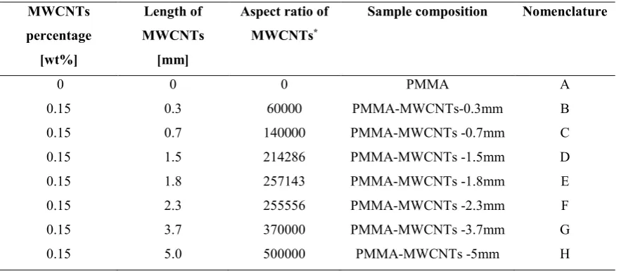
furnace. The AR of the MWCNTs synthesised are listed in Table 1.
2.2.2. Composite preparation
The PMMA pellets were first ground to powder yielding a particle size smaller than 250
μm, using a SPEX®SamplePrep Freezer Mill (Stanmore, UK). The pellets (25 g batch) were
pre-cooled for 12 minutes, followed by two 5 minute grinding cycles at 15 Hz. Between each
cycle, the sample was cooled for a 2 minute interval. The PMMA powder was dried in a
vacuum oven at 70 C for 12 h prior to melt processing to prevent water absorption and
consequent deterioration in material properties.
Composites were prepared by first dry blending the PMMA powder with 0.15 wt% of
the different MWCNTs by hand. The powder mixtures were fed 10 g at a time into a Haake™
Mini-Lab II micro-compounder fitted with two conical co-rotating screws that facilitated
recirculation of compound within a chamber of volume 5 cm3. The mixture was mixed for 5
minutes at 80 rpm and 235 C. After 5 minutes, the nanocomposite was extruded through a
3.90 mm × 1.20 mm rectangular die directly into the hot melt chamber of a micro-injection
moulding machine. Test specimens were injection moulded using a piston injection moulding
system (Thermo-Scientific Haake™ MiniJet Pro) to produce standard dumbbell-shaped
specimens conforming to ASTM D638 V for tensile testing and disk samples (d=25 mm, h=1.5
mm) for rheology measurements. The injection temperature was set to 230 C, while the mould
temperature to 140 C with an injection pressure of 350 bar. Neat PMMA was also extruded
and injection moulded using the same parameters for the purpose of comparison. All sample
[image:10.595.72.514.188.381.2]types prepared are listed in Table 1.
Table 1: Neat PMMA and composites of PMMA-MWCNTs
MWCNTs percentage
[wt%]
Length of MWCNTs
[mm]
Aspect ratio of MWCNTs*
Sample composition Nomenclature
0 0 0 PMMA A
0.15 0.3 60000 PMMA-MWCNTs-0.3mm B
0.15 0.7 140000 PMMA-MWCNTs -0.7mm C
0.15 1.5 214286 PMMA-MWCNTs -1.5mm D
0.15 1.8 257143 PMMA-MWCNTs -1.8mm E
0.15 2.3 255556 PMMA-MWCNTs -2.3mm F
0.15 3.7 370000 PMMA-MWCNTs -3.7mm G
0.15 5.0 500000 PMMA-MWCNTs -5mm H
*Length to external diameter ratio of MWCNTs
2.3. Characterisation
Samples for the high resolution transmission electron microscope (HRTEM) studies
were prepared by dispersing a section of the CNT carpet in isopropanol with gentle sonication
for an hour, and then placing one drop of the solution on a 300 mesh Cu lacey carbon grid
(from SPI).
Scanning Electron Microscopy (SEM) examination of all materials was carried using a
Zeiss Sigma SEM with an operating voltage of 3.0 kV. Specimens for SEM examination were
taken from dumbbells after fracturing in liquid nitrogen, then mounted on 25 mm × 1 mm
aluminium discs using carbon tape, and subsequently sputtered with a 10–20 nm thick coating
of gold on the sample surface to impede charging effects and induce conductivity prior to SEM
examination. 3
Differential Scanning Calorimetry (DSC) measurements on PMMA and
PMMA-MWCNTs composites were performed using a Mettler-Toledo DSC (DSC1, model 700) under
flowing nitrogen (flow rate of 20 mL min-1). The instrument was calibrated using the onset
melting temperature and melting enthalpy of indium standards. Samples (5–10 mg) were sealed
in aluminium pans and heated from 30 C to 200 °C at 10 K min-1. In all cases, samples were
held at 200 °C for 1 min and cooled to 30 °C at 10 K min-1 then reheated again to 200 C at 10
K min-1. All DSC measurements were repeated in triplicate for each composition and the
relevant thermal parameters determined using a STARe Version 12.10 software package.
Thermo-gravimetric Analysis (TGA) was carried out in a TGA Analyser TGA/SDTA
851e/LF/1600/1382 (Mettler Toledo). Specimens ranging between 5 mg and 10 mg of each
sample was loaded in aluminium pans and heated from 30 °C to 800 °C at a heating rate of 10
K min-1 under flowing nitrogen (flow rate of 50 mL min-1). The onset decomposition
temperatures were determined from the weight loss curve by extrapolating the curve at 5 wt%
weight loss for each composition.
Dynamic properties (storage modulus (E՛), loss modulus (E՛՛) and tan δ) of all samples
(35 mm × 10 mm × 3.2 mm) were measured using a Tritec 2000 dynamic mechanical thermal
analysis (DMTA) instrument. The experiments were conducted in the temperature range 25 C
to 160 °C and a heating rate of 2 K min-1 at a frequency of 1 Hz. Tests were conducted in the
dual cantilever bending mode at 0.015 mm displacement.
Dynamic rheological measurements were performed using a HAAKE MARS rotational
rheometer in an oscillatory shear mode using parallel plate geometry (standard aluminium plate,
25 mm diameter, 1 mm gap) at 235 °C. Frequency sweeps from 1000 rad/s to 0.1 rad/s were
carried out at low stress (10 Pa), which was shown to be within the linear viscoelastic limit of
all the materials used in this study. 3
Tensile tests were performed on all composites and Young’s modulus (GPa), ultimate
tensile strength (MPa) and strain at break (%) determined using a Shimadzu Autograph
AGS-X fitted with a 10 kN load cell, equipped with a twin TRViewAGS-X non-contact digital video
extensometer (500 mm and 120 mm field of view) using Trapezium X Version 1.4 software
package. The standard dumbbell-shaped test specimens (ASTM D638 V) were deformed using
a constant crosshead speed of 1 mm/min and data acquisition rate of 100 points/s. The dumbbell
samples had a total length of 63.5 mm, a gauge length of 7.62 mm, a neck width of 3.18 mm,
and a thickness of 3.3 mm. The thickness and width of the samples were determined using a
micro-meter prior to testing. Five samples from each batch were run to obtain average and
standard deviation values. To obtain the elastic modulus, a linear regression technique was
utilized to define the slope of the stress-stain curve in the initial region before yield.Analysis
of variance (ANOVA) was utilised to test for any significant differences amongst the mean of
the tensile property of interest by quantifying the differences with the aid of Data Analysis
ToolPak in MS Excel, with the p-value set to 5%.
3. Results and discussion
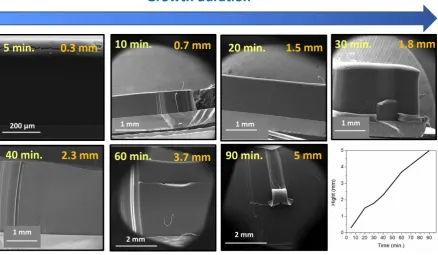
Figure 1 shows SEM images of MWCNT dense carpets as a function of growth duration
which were synthesized with heights of 0.3, 0.7, 1.5, 1.8, 2.3, 3.7 and 5 mm (± 5% based on
SEM images) for 5, 10, 20, 30, 40, 60 and 90 minutes, respectively. From observation of SEM
images, we can estimate that the height variation by appropriately using gas preheating [25, 29,
30] and, by controlling the amount of water vapour introduced in the reactor by combining
hydrogen and the oxygen contained in ArO2 (mixture of 1% oxygen and 99% argon) [25, 28,
31]. We can limit Ostwald ripening (coarsening) of the catalyst [32] and formation of
amorphous carbon [31] on the catalyst surface, thus extending its lifetime. This allows us to
modulate the height of these CNT carpets with growth times up to 90 minutes. 3
Figure 1: SEM images of the carpet height of MWCNTs grown on Si/Al2O3 10 nm/Fe 1.8 nm
obtained for various growth durations from 5 to 90 minutes. Bottom right side,average CNT carpet height as a function of growth duration as described in the text.
TEM images of the dispersed MWCNTs in iso-propanol (Figure 2) show that the
diameter of the MWCNTs increased with growth duration as a result of the coarsening process
that formed larger Fe catalysts leading to thicker CNT tubes. For 5, 10, 20, 30, 40, 60, and 90
mins. growth duration, MWCNTs having diameters of 5, 5, 7, 7, 9, 10 and 10 nm were obtained,
respectively. All samples exhibit a high degree of crystallinity. The reason why the diameters
of the CNTs do not vary in a very significant manner when the growth time is increased from
5 to 90 minutes may be attributed to the positive effect of water vapour in limiting Ostwald
ripening [32], thus limiting the growth in size of the catalyst and therefore the increase in
diameter of the CNTs. 3
Figure 2: TEM images of grown crystalline MWCNTs obtained by various growth duration from 5 to 90 minutes.
By way of example, fractured surfaces of the PMMA-MWCNTs-1.5mm composite are
shown in Figure 3(a) and (b). Combined both images indicate a relatively high degree of
MWCNT dispersion in the PMMA matrix. The MWCNTs were embedded in the matrix with
protruded ends revealed at the fractured surface. Few voids were obvious suggesting a high
level of wetting of the MWCNTs by the polymer. Fig. 3(b) shows MWCNT agglomerations
and smaller bundles throughout the PMMA matrix. At such a relatively low MWCNT loading
(0.15 wt%) strong van der Waal interactions between neighbouring tubes and a very low
concentration of MWCNTs in the nanocomposite (0.15 wt%) will contribute to the inability to
form a 3-D interconnected MWCNT network in the matrix polymer. Some voids can be seen
on the surface of PMMA-MWCNTs-1.5mm composite (as indicated with arrows in Fig. 3(a)),
most probably as a consequence of air trapped during the manufacturing process. Moreover,
voids can also be formed when the MWCNTs are pulled out from the matrix during
cryo-fracturing specimens for SEM studies. 3
Figure 3: SEM images of fractured surfaces of a composite of PMMA with MWCNTs having a length of 1.5mm.
TGA and DTG curves for unfilled PMMA and the composites of PMMA and
MWCNTs are shown in Figure 4(a) and (b), respectively. For all the composites, the thermal
stability of the PMMA was unchanged with increasing MWCNT length, even though the
MWCNTs are more thermally labile than pure PMMA. This is in part expected to be due to the
very low concentration of MWCNTs (0.15 wt%) added. Both systems degraded via one clear
step confirming the MWCNTs did not alter the mechanism of thermal degradation of PMMA,
as has been reported previously [33]. It can be seen from the DTG curves (Fig. 4(b)) that when
the temperature reached about 380 °C, all samples started to decompose, peaking at about
400 °C, until all material degraded by 440 °C. Classically, the onset of thermally induced
depolymerisation of PMMA occurs between 300 °C and 320 °C. Thus, as the melt
compounding of the PMMA-MWCNTs composites was performed at 235 °C, much lower than
their degradation temperature (~380 °C), there was no degradation of PMMA during melt
processing. It is important to confirm this finding to eliminate the effect of PMMA thermal
degradation when trying to assess the correlation between MWCNT length (aspect ratio) and
mechanical properties of the PMMA-MWCNT composites.
(a)
(b)
[image:16.595.173.454.73.482.2]
Figure 4: (a) TGA and (b) DTG curves for PMMA and composites of PMMA and MWCNTs.
The glass transition temperature (Tg) of PMMA and the composites of PMMA and
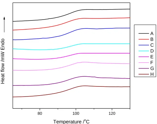
MWCNTs were determined from DSC measurements. The DSC thermograms (upon second
heating to erase any effect of thermal history) are shown in Figure 5. Allowing for instrument
error, the Tg for pristine PMMA (step in heat flow and calculated as the midpoint of the
extrapolated heat flow) was 97.5 °C. The Tg of the PMMA-MWCNT systems did not show
significant change when compared with neat PMMA, the largest change was observed for the
composite with the longest MWCNTs 5mm (H), where Tg decreased by about ~0.5 °C
compared with unfilled PMMA. This suggests that MWCNTs did not hinder the thermal
100 200 300 400 500 600
0% 20% 40% 60% 80% 100%
Ma
ss loss
Temperature /oC
A B C D E F G H
(a)
100 200 300 400 500 600
Temperature /o
C
A B C D E F G H
(b)
DTG
motion of the polymer chains [34], but as DSC is an indirect measurement method for Tg of
polymers [35, 36], additional measurements were performed to more accurately determine Tg
from DMTA, see Figure 6.
80 100 120
Heat
fl
ow /mW End
o
Temperature /oC
[image:17.595.169.427.159.362.2]A B C D E F G H
Figure 5: DSC thermograms for PMMA and composites of PMMA and MWCNTs
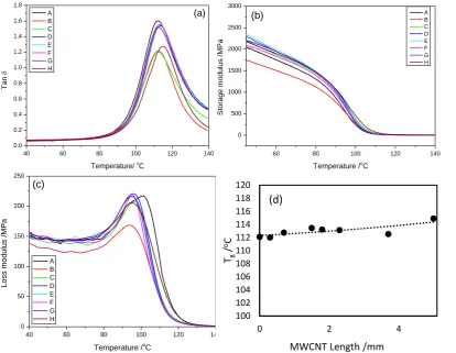
The variation in tan δ, storage modulus (Eʹ) and loss modulus (Eʺ) as a function of
temperature and, Tg of the PMMA-MWCNT composites as a function of MWCNT length are
plotted in Figure 6. In the temperature ranged examined (-40 oC to +140 oC) one relaxation
process was obtained in the tan δ plot which can be assigned to the glass transition process of
PMMA [37]. From Figure 6(d) it can be observed that the Tg of PMMA increased from about
112 oC for neat PMMA (A) to 116 oC for the composite with the longest MWCNTs at 5mm
(H). Even for such a relatively low concentration of MWCNTs (0.15 wt%), the longer the
MWCNTs the greater the probability the tubes hinder PMMA chains dynamics via
entanglements with the net effect of increased Tg. As might be expected the effect is greater
the longer the MWCNTs. Below Tg, the general trend was for Eʹ to increase by about 10% with
increasing MWCNT length, Figure 6 (b). Above Tg, Eʹ was the same for all the composites
irrespective of the tube length. 3
Figure 6: Variation in (a) tan δ, (b) storage modulus, E', and (c) loss modulus, E" of PMMA and composites of PMMA and MWCNTs as a function of temperature and (d) plot of Tg as a
function of MWCNT length.
The increase in Tg of PMMA on the addition of MWCNTs with increasing length
further suggests the longer the tube length the greater the probability that PMMA chain
dynamics is hindered by a combination of PMMA-MWCNT entanglements and possibly some
degree of MWCNT alignment. This hypothesis was tested by studying the effect of MWCNT
addition on the viscoelastic behaviour of PMMA. Oscillatory stress sweep tests were
performed to establish the linear viscoelastic region and, determine the maximum stress for
linear behaviour at 235 °C. The limit of the linear viscoelastic regime was determined by the
stress magnitude at which the dynamic shear moduli (G' and G") started decreasing and became
40 60 80 100 120 140
0.0 0.2 0.4 0.6 0.8 1.0 1.2 1.4 1.6 1.8 Ta n
Temperature/ o
C A B C D E F G H (a)
60 80 100 120 140
0 500 1000 1500 2000 2500 3000 Stora ge mo du lus /M Pa
Temperature /oC
A B C D E F G H (b)
40 60 80 100 120 140
0 50 100 150 200 250 Lo ss mo du lus /M Pa
Temperature /o
C A B C D E F G H (c) 100 102 104 106 108 110 112 114 116 118 120
0 2 4
Tg
/
oC
MWCNT Length /mm
non-linear. As a result, a stress value of 10 Pa was selected for all the samples used in this
study.
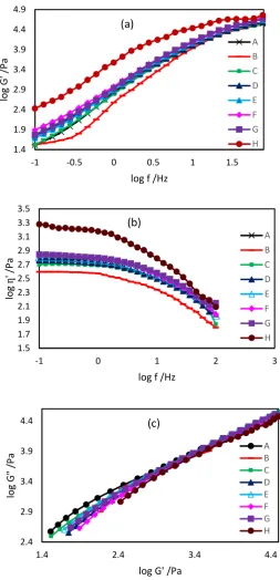
As shown in Figure 7(a), the storage modulus, G' increased with increasing MWCNT
length by about one order of magnitude for the composite with the longest tubes - 5mm. This
increase was obtained for a MWCNT loading of 0.15wt%, clearly below any percolation
threshold. Similar behaviour was obtained for shear viscosity ' at low frequencies (<5 Hz),
see Figure 7(b). A Cole–Cole plot (log G' versus log G" plot) is a useful tool that can probe
composite miscibility/compatibility, where deviation from the linear relationship between G'
and G" can indicate poor interaction between PMMA and each MWCNTs in this case. In
particular, the curves corresponding to composites with MWCNTs with different length deviate
slightly from each other and from pure PMMA as shown in Figure 7(c) and indicates decreasing
interactions between PMMA and MWCNTs with increasing nanotube length, evidence for
induced heterogeneity within the composite material [38]. 3
Figure 7 Change in (a) storage modulus (G') and (b) shear viscosity (ƞ') as a function of frequency and, (c) plot of log G' versus log G" (Cole–Cole plot) for PMMA and composites of PMMA and MWCNTs at 235 °C.
1.4 1.9 2.4 2.9 3.4 3.9 4.4 4.9
-1 -0.5 0 0.5 1 1.5
log
G
' /Pa
log f /Hz
A B C D E F G H (a)
1.5 1.7 1.9 2.1 2.3 2.5 2.7 2.9 3.1 3.3 3.5
-1 0 1 2 3
log
ƞ
' /P
a
log f /Hz
A B C D E F G H (b)
2.4 2.9 3.4 3.9 4.4
1.4 2.4 3.4 4.4
log
G
"
/Pa
log G' /Pa
A B C D E F G H (c)
[image:20.595.161.415.95.621.2]Quasi-static tensile testing was performed at room temperature (RT) on PMMA and
composites of PMMA and MWCNTs to determine their stress-strain curves, and associated
mechanical properties. At the macroscopic level, all materials exhibit a narrow linear elastic
stress-strain regime, beyond which the mechanical behaviour is dominated by a nonlinear
stress-strain response. We believe that at the nanoscopic level there is an irreversible (beyond
the elastic limit) process of straightening, slipping, and bundling of MWCNTs during straining,
as suggested in [39], which is accompanied by some molecular alignment of PMMA chains.
The stress-strain curves for PMMA and the nanocomposites are shown in Figure 8(a).
The Young’s modulus was determined from the initial slope on the stress-strain curve, while
the tensile strength was defined as the maximum stress before material failure. The strain at
break was determined as the maximum strain before material failure. It was found that there is
no statistically significant change of Young’s modulus (E) (as assessed by ANOVA analysis)
of the pure PMMA and PMMA-MWCNT systems with increasing MWCNT length from 0.3
mm up to 3.7 mm. This behaviour may be a consequence of the very low (0.15 wt%) filler
content. However, E of PMMA-MWCNTs-5mm (H) composite was found to be higher than
that of the pure PMMA and other PMMA-MWCNT composites (see Figure 8(b)).
The tensile strength of PMMA-MWCNT composites (see Figure 8(c)) increased with
increasing MWCNT length from 52.7 MPa for pure PMMA to 64.7 MPa for
PMMA-MWCNTs-3.7mm (G). This improvement is believed to be due to good interfacial interaction
between MWCNTs and PMMA expected as a result of the large aspect ratio of MWCNTs
which act as enhanced fibres in the composites. However, the tensile strength of
PMMA-MWCNTs-5mm (H) is lower than that of PMMA-MWCNTs-3.7mm (G). Moreover, the
difference is not statistically significant as assessed by ANOVA analysis. This is also related
to the low content of MWCNTs. 3
The variation of strain at break for PMMA and the PMMA-MWCNTs composites with
MWCNT length are shown in Figure 8(d). Similarly, the strain at break for the
PMMA-MWCNT systems increased with increasing PMMA-MWCNT length, from 1.8% for PMMA to 4.3%
for PMMA-MWCNTs-3.7mm (G) (except for PMMA-MWCNTs-5mm (H), which exhibit a
similar value of strain to failure as PMMA-MWCNTs-3.7mm (G) systems). The above trend
may be caused by bridging PMMA chains by the MWCNTs that act as tie chains, resulting in
the increase of the average number of physical junction points with the incorporation of
MWCNTs [40]. Thus, it can also be speculated that sufficiently long tubes can provide
enhanced interfacial interactions with PMMA, and lead to improved toughness (area under the
stress–strain curve) [41].
In addition to the experimental data, Mori-Tanaka theory [42] was used to predict the
Young’s modulus of the nanocomposites as a function of MWCNT length. For this, the
nanotubes were modelled as straight effective fibres described by linear elastic and isotropic
properties, with their Young’s modulus and Poisson’s ratio values equal to 143.62 GPa and
0.16, respectively, as calculated in [43]. For simplicity, this approximation neglected the
presence of multiple walls in each nanotube, their transversely isotropic behaviour and
waviness. The MWCNTs were assumed to be well dispersed, aligned or randomly oriented and
perfectly bonded to the PMMA, the latter was modelled as an isotropic linear elastic material
with Young’s modulus and Poisson’s ratio equal to 3.3 GPa and 0.35, respectively. The weight
fraction of MWCNTs was converted into their volume fraction using Eq. (1) in [44]. For
randomly oriented nanotubes, the orientation-averaged Mori-Tanaka elasticity tensor [45] was
used with the Eshelby tensor for high-aspect ratio ellipsoidal inclusions that resemble fibres.
As expected the model generally predicted a small reinforcing effect, brought by the addition
of a tiny amount of MWCNTs (0.15% wt.), for both aligned and randomly oriented nanotubes, 3
as shown in Fig. 8(e). The predicted values are clearly larger than from the experimental results
[image:23.595.74.478.160.591.2](except the PMMA-MWCNTs-5mm sample).
Figure 8: (a) stress-strain curves, (b) Young’s modulus, (c) tensile stress and (d) strain at break for PMMA and PMMA/MWCNT composites as a function of MWCNT length and (e)
0 1 2 3 4 5
0 2 4
Stra in a t b re ak /%
MWCNT Length /mm
1.5 2 2.5 3 3.5 4
0 2 4
Yo u n g' s m o d u lu s /G Pa
MWCNT Length /mm
20 30 40 50 60 70 80
0 2 4
Te n sile s tres s /MPa
MWCNT Length /mm
0.6 0.7 0.8 0.9 1 1.1 1.2 1.3
0 1 2 3 4 5
N o rm alis ed Y o u n g' s Mo d u lu s
MWCNT Length /mm
Mori-Tanaka model predictions for randomly orientated MWCNTs
Mori-Tanaka model predictions for aligned MWCNTs
Experimental
(e)
(d)
0 1 2 3 4 5
0 10 20 30 40 50 60 70
0.0 0.1 0.2 0.3 0.4 0 2 4 6 8 10 12 14 16 18 Te nsile st re ss /M Pa
Tensile strain /%
normalised Young’s modulus as a function of MWCNT length from the Mori-Tanaka model and experimental data.
This difference between predicted and experimental values is most probably associated
with a weak interface and MWCNT agglomeration in the experimental samples, effects that
have not yet been captured in our model. Moreover, no effect of the MWCNT length (aspect
ratio) on the modulus was observed within the MWCNT length range investigated. It was found
that the model predicted increases in the modulus of the nanocomposites up to the aspect ratio
of around 10000 (these results are not shown here), similar to [46], i.e. below the range of
MWCNT lengths (aspect ratios) investigated experimentally in this work. It is noteworthy to
mention that the experimental results for PMMA-MWCNTs-5mm exceed model predictions
for randomly oriented nanotubes, behaviour associated with the combined effects of some
degree of MWCNT alignment, and a possible increase of junction points between MWCNTs
and PMMA, as mentioned earlier. This highlights the importance of further improvement of
micromechanical models, such as those based on the Mori-Tanaka theory, to account for
different scenarios of MWCNT-polymer (imperfect bonding, physical junction points) and
MWCNT-MWCNT (agglomerations) interactions.
4. Conclusions
The effect of MWCNT length (and aspect ratio) on the thermal and mechanical properties
of lightly loaded (0.15% wt) composites of PMMA and MWCNTs was investigated for
MWCNTs having lengths between 0.3mm and 5mm. MWCNT length had no effect on the
thermal degradation properties of PMMA. The Tg of PMMA increased by up to 4 ºC on
addition of longest tubes (5mm) as the longer tubes are more likely to hinder polymer chain
mobility via physical entanglements. Consequently, Gʹ and η’ of the composites were greater
than that for unfilled PMMA. Additionally, the rheological behaviour of these blends 3
confirmed increased heterogeneity with increasing MWCNT length (aspect ratio). The
quasi-static mechanical properties of the nanocomposites, tensile stress and strain to failure, increased
with increasing MWCNT length. However, no improvement in Young’s modulus on the
addition of MWCNTs to PMMA was recorded with the exception of the composite system
with the longest MWCNTs (5 mm), where the modulus increased by more than 20%. These
results suggest relatively weak interfacial interactions and/or a high level of MWCNT
agglomeration for the tubes with a length below 5 mm. The nanotubes of length 5 mm, have
the ability to form physical junction points with polymer chains, and thus lead to enhanced
PMMA-MWCNTs interactions and increased mechanical properties. Predictions of
nanocomposite Young’s modulus with the Mori-Tanaka theory show that future
micromechanical models should account for MWCNT agglomeration and polymer-nanotube
interactions as a function of CNT length.
Acknowledgements
The authors thank Martin Worrall and Jaipal Gupta for technical assistance. 3
References
1. McNally T, Pötschke P. Polymer-carbon nanotube composites: Preparation, properties and applications. 1st ed. Cambridge: Elsevier; 2011.
2. Ajayan PM, Zhou OZ. Applications of carbon nanotubes, Carbon Nanotubes 2001; 80:391-425. 3. Treacy MJ, Ebbesen T, Gibson J. Exceptionally high Young's modulus observed for individual
carbon nanotubes. Nature 1996; 381(6584): 678-680.
4. Oh JY, Choi YS, Yang SJ, Kim J, Choi HS, Choi GD, et al. Effect of microstructure and morphological properties of carbon nanotubes on the length reduction during melt processing. Compos Sci Technol 2015; 112: 42-49.
5. Abbasi SH, Al-Juhani AA, UI-Hamid A, Hussein IA. Effect of aspect ratio, surface modification and compatibilizer on the mechanical and thermal properties of ldpe-mwcnt nanocomposites. e-Polymers 2011; 11(1): 722-738.
6. Kumar RM, Sharma SK, Kumar BM, Lahiri D. Effects of carbon nanotube aspect ratio on strengthening and tribological behavior of ultra high molecular weight polyethylene composite. Compos Part A 2015; 76: 62-72.
7. Wu D, Wu L, Zhou W, Sun Y, Zhang M. Relations between the aspect ratio of carbon nanotubes and the formation of percolation networks in biodegradable polylactide/carbon nanotube composites. J Polym Sci Part B Polym Phys 2010; 48(4): 479-489.
8. McClory C, McNally T, Baxendale M, Pötschke P, Blau W, Ruether M. Electrical and rheological percolation of PMMA/MWCNT nanocomposites as a function of CNT geometry and functionality. Eur Polym J 2010; 46(5): 854-868.
9. Verma P, Saini P, Choudhary V. Designing of carbon nanotube/polymer composites using melt recirculation approach: Effect of aspect ratio on mechanical, electrical and EMI shielding response. Mater Des 2015; 88:269-277.
10. Dubnikova I, Kuvardina E, Krasheninnikov V, Lomakin S, Tchmutin I, Kuznetsov S. The effect of multiwalled carbon nanotube dimensions on the morphology, mechanical, and electrical properties of melt mixed polypropylene‐based composites. J Appl Polym Sci 2010; 117(1): 259-272.
11. Chen Z, Zeng C, Zhang C, Wang B, Cao K, Yao Z. Preparation and properties of cyclic olefin copolymers multiwalled carbon nanotube nanocomposites. J Appl Polym Sci 2012; 126(3): 1121-1128.
12. Guo J, Liu Y, Prada-Silvy R, Tan Y, Azad S, Krause B, Potschke P, et al. Aspect ratio effects of multi‐walled carbon nanotubes on electrical, mechanical, and thermal properties of polycarbonate/MWCNT composites. J Polym Sci Part B Polym Phys 2014; 52(1):73-83.
13. Duncan RK, Qiao R, Bult JB, Burris D, Burinson LC, Schadler LS. Viscoelastic behavior of nanotube-filled polycarbonate: Effect of aspect ratio and interface chemistry. Int J Sma Nano Mater 2010; 1(1): 53-68.
14. Ayatollahi MR, Shadlou S, Shokrieh MM, Chitsazzadeh M. Effect of multi-walled carbon nanotube aspect ratio on mechanical and electrical properties of epoxy-based nanocomposites. Polym Test 2011; 30(5): 548-556.
15. Hernández-Pérez A, Aviles F, May-Pat A, Valadez-Gonzalez, Herrera-Franco PJ, Bartolo-Perez P. Effective properties of multiwalled carbon nanotube/epoxy composites using two different tubes. Compos Sci Technol 2008; 68(6):1422-1431
16. Prolongo SG, Meliton BG, Jimenez-Suarez A, Urena A. Study of efficiency of different commercial carbon nanotubes on manufacturing of epoxy matrix composites. J Compos Mater 2014; 48(25): 3169-3177.
17. Alva A, Raja S. Damping characteristics of epoxy-reinforced composite with multiwall carbon nanotubes. Mech Adv Mater and Struct 2014; 21(3): 197-206.
18. Li W, He D, Bai J. The influence of nano/micro hybrid structure on the mechanical and self-sensing properties of carbon nanotube-microparticle reinforced epoxy matrix composite. Compos Part A Appl Sci Manuf 2013; 54: 28-36.
19. Marton A, Faiella G, Antonucci V, Giordano M, Zarrelli M. The effect of the aspect ratio of carbon nanotubes on their effective reinforcement modulus in an epoxy matrix. Compos Sci Technol 2011; 71(8): 1117-1123.
20. Wang X, Jiang Q, Xu W, Cai W, Inoue Y, Zhu Y. Effect of carbon nanotube length on thermal, electrical and mechanical properties of CNT/bismaleimide composites. Carbon 2013; 53: 145-152.
21. Söffker GH, Deplazes A. Constructing architecture: materials, processes, structures, a handbook. 3rd ed. Berlin:Springer; 2005.
22. Nessim GD, Hart AJ, Kim JS, Acquaviva D, Oh J, Morgan CD, et al. Tuning of vertically-aligned carbon nanotube diameter and areal density through catalyst pre-treatment. Nano Lett 2008;
8(11): 3587-3593.
23. Nessim GD, Seito M, O'Brien KP, Speakman SA. Dual formation of carpets of large carbon nanofibers and thin crystalline carbon nanotubes from the same catalyst-underlayer system. Carbon 2010; 48(15): 4519-4526.
24. Basaran D, Aleksandrov HA, Chen Z, Zhao Z, Rosch N. Decomposition of ethylene on transition metal surfaces M (111). A comparative DFT study of model reactions for M= Pd, Pt, Rh, Ni. J Mol Catal A Chem 2011; 344(1):37-46.
25. Teblum E, Itzhak A, Shawat-Avraham E, Muallem M, Yemini R, Nessim GD. Differential preheating of hydrocarbon decomposition and water vapor formation shows that single ring aromatic hydrocarbons enhance vertically aligned carbon nanotubes growth. Carbon 2016;
109:727-736.
26. Somekh M, Shawat E, Nessim GD. Fully reproducible, low-temperature synthesis of high-quality, few-layer graphene on nickel via preheating of gas precursors using atmospheric pressure chemical vapor deposition. J Mater Chem A 2014; 2(46): 19750-19758.
27. Nessim GD, Seita M, O'Brien KP, Hart AJ, Bonaparte RK, Mitchell RR, et al. Low temperature synthesis of vertically aligned carbon nanotubes with electrical contact to metallic substrates enabled by thermal decomposition of the carbon feedstock. Nano lett 2009; 9(10):3398-3405. 28. Nessim GD, Al-Obeidi A, Grisaru H, Polsen ES, Oliver CR, Zimrin T, et al. Synthesis of tall carpets of vertically aligned carbon nanotubes by in situ generation of water vapor through preheating of added oxygen. Carbon 2012; 50(11):4002-4009.
29. Nessim GD, Seita M, Plata DL, O'Brien KP, Hart AJ, Meshot ER, et al. Precursor gas chemistry determines the crystallinity of carbon nanotubes synthesized at low temperature. Carbon 2011; 49(3):804-810.
30. Meshot ER, Plata DL, Tawfick S, Zhang Y, Verploegen EA, Hart AJ. Engineering vertically aligned carbon nanotube growth by decoupled thermal treatment of precursor and catalyst. ACS Nano 2009; 3(9):2477-2486.
31. Hata K, Futaba DN, Mizuno K, Namai T, Yumura M,Lijima S. Water-assisted highly efficient synthesis of impurity-free single walled carbon nanotubes. Science 2004; 306(5700):1362-1364.
32. Amama PB, Pint CL, McJilton L, Kim SM, Stach EA, Murray PT, et al. Role of water in super growth of single-walled carbon nanotube carpets. Nano lett 2009; 9(1):44-49.
33. Costache MC, Wang D, Heidecker MJ, Manias E, Wilkie CA. The thermal degradation of poly (methyl methacrylate) nanocomposites with montmorillonite, layered double hydroxides and carbon nanotubes. Polym Adv Technol 2006; 17(4): 272-280.
34. Kalakonda P, Banne S. Thermomechanical properties of PMMA and modified SWCNT composites. Nanotechnol Sci Appl 2017; 10: 45-52.
35. Dean JA. Analytical chemistry handbook. 1st ed. New York:McGraw-Hill; 1995.
36. Skoog DA, Holler FJ, Crouch SR. Principles of instrumental analysis. 7th ed. Boston:Cengage learning; 2017.
37. Ash BJ, Siegel RW, Schadler LS, Glass‐transition temperature behavior of alumina/PMMA nanocomposites. J Polym Sci Part B: Polym Phys 2004; 42(23): 4371-4383.
38. Han CD, Chuang HK. Criteria for rheological compatibility of polymer blends. J Appl Polym Sci 1985; 30(11): 4431-4454.
39. Xu M, Futaba DN, Yamada T, Yumura M, Hata K. Carbon nanotubes with temperature-invariant viscoelasticity from–196 to 1000 C. Science 2010; 330(6009): 1364-1368.
40. Hlangothi SP, Krupa I, Djokovic V, Luyt AS. Thermal and mechanical properties of cross-linked and uncross-linked linear low-density polyethylene–wax blends. Polym Degrad Stab 2003;
79(1):53-59.
41. Sharma A, Tripathi B, Vijay YK. Dramatic improvement in properties of magnetically aligned CNT/polymer nanocomposites. J Membr Sci 2010; 361(1): 89-95.
42. Mori T, Tanaka K. Average stress in matrix and average elastic energy of materials with misfitting inclusions. Acta Metall 1973; 21(5): 571-574.
43. Weidt D, Figiel Ł. Finite strain compressive behaviour of CNT/epoxy nanocomposites: 2D versus 3D RVE-based modelling. Comput Mater Sci 2014; 82:298-309.
44. Weidt D, Figiel Ł. Effect of CNT waviness and van der Waals interaction on the nonlinear compressive behaviour of epoxy/CNT nanocomposites. Compos Sci Technol 2015; 115:52-59. 45. Figiel Ł, Buckley CP. Elastic constants for an intercalated layered-silicate/polymer nanocomposite using the effective particle concept – A parametric study using numerical and analytical continuum approaches. Comput Mater Sci 2009; 44(4):1332-1343.
46. Sheng N, Boyce MC, Parks DM, Rutledge GC, Abes JI, Cohen RE. Multiscale micromechanical modeling of polymer/clay nanocomposites and the effective clay particle. Polymer 2004; 45(2):487- 506.