DENOISING BASED ON MULTI
*
Department of Electronic &
ARTICLE INFO ABSTRACT
This paper presents a new
restoration. It is designed to eliminate the errors or quality degradation in image by the means of multi filtering techniques. This work uses Pseudo Inverse Filter and Wiener Filter techniques of filtering. With the help of this hybrid method, proposed work denoises the image and improve the quality of the image. Digital image processing has been and will continue tohave an important role to extremely varied applications. Proposed work is implement
clearly about the restoration of degraded image.
Copyright © 2015 Princy Singhand Rahul Dubey. This
unrestricted use, distribution, and reproduction in any medium, provided the original work is properly cited.
INTRODUCTION
Image noise is an undesirable by-product of image acquisition or transmission. Denoising is one of the important pre processing steps in various image processing and analysis applications. The main aim of image denoising is to remove noise while preserving the important signal features. Noise reduction techniques are conceptually similar rega
image being processed; however a prior knowledge of the characteristics of an expected image can govern the implementations of these techniques. A total figure of de noising techniques are present for the removal of several types of noises like as Gaussian, Speckle, Salt & Pepper etc. where linear and non-linear techniques are also there. Noise possesses Gaussian-like distribution is mostly found in real images. The zero mean property of that Gaussian distribution permits that noise to be eradicated through locally averaging pixel values. Past linear filters like as arithmetic mean filter and Gaussian filter smooth noises strongly but distort edges and
contours (Jimmy Singla, 2012). The Wiener filter refers as
mean square error-optimal stationary linear filter for the purpose of images degraded through additive noise and blur. A general disadvantage of the actual use of this technique is that they usually require some ‘a priori’ information about the
*Corresponding author: Princy Singh,
Department of Electronic & Communication Engineering, Oriental (OIST) College, RGPV University, India
ISSN: 0975-833X
Vol.
Article History:
Received 23rd August, 2015
Received in revised form 18th September, 2015
Accepted 27th October, 2015
Published online 30th November,2015
Key words:
Image, Image Processing, Filtering, Denoising.
Citation: Princy Singhand Rahul Dubey, 2015. “
Current Research, 7, (11), 22469-22473.
RESEARCH ARTICLE
DENOISING BASED ON MULTI-LEVEL FILTERING IN IMAGE PROCESSING
*Princy Singh
and Rahul Dubey
Department of Electronic & Communication Engineering, Oriental (OIST) College
RGPV University, India
ABSTRACT
This paper presents a new denoising based multi-level filtering technique algorithm for image restoration. It is designed to eliminate the errors or quality degradation in image by the means of multi filtering techniques. This work uses Pseudo Inverse Filter and Wiener Filter techniques of filtering. With the help of this hybrid method, proposed work denoises the image and improve the quality of the image. Digital image processing has been and will continue tohave an important role to extremely varied applications. Proposed work is implemented in .NET. Results show very much clearly about the restoration of degraded image.
This is an open access article distributed under the Creative Commons Att use, distribution, and reproduction in any medium, provided the original work is properly cited.
product of image acquisition is one of the important pre-processing steps in various image pre-processing and analysis applications. The main aim of image denoising is to remove noise while preserving the important signal features. Noise reduction techniques are conceptually similar regardless of the image being processed; however a prior knowledge of the characteristics of an expected image can govern the implementations of these techniques. A total figure of de-noising techniques are present for the removal of several types
ke as Gaussian, Speckle, Salt & Pepper etc. where linear techniques are also there. Noise possesses like distribution is mostly found in real-world images. The zero mean property of that Gaussian distribution e eradicated through locally averaging pixel values. Past linear filters like as arithmetic mean filter and Gaussian filter smooth noises strongly but distort edges and . The Wiener filter refers as ationary linear filter for the purpose of images degraded through additive noise and blur. A general disadvantage of the actual use of this technique is that they usually require some ‘a priori’ information about the
Department of Electronic & Communication Engineering, Oriental
spectra of that noise and the actual signal. Unluckily, such information is mostly not available. This makes the linear orspatial techniques less attrac
Alternatively non-linear methods were proposed for denoising. They are mostly based on multi
wavelet transform (Yun Yin et al
Here in wavelet domain, the noise is constantly
coefficients, at that time overall image information is focused on few largest ones due to its sparse representation. The most straightforward way of distinguishing information from noise in the wavelet domain consists of thresholding the
coefficients (Donoho and Johnstone, 1994
wavelet is then compared with known threshold and is taken to zero, when the magnitude is low as compare to threshold; or it is kept or modified depending on hard or soft thresholding schemes. Since 2-D Wavelet is tensor product of 1
it has only three directions, viz. vertical, horizontal and diagonal. So 2-D Wavelet is effective at approximating point singularities than line singularities like edges. The tensor product wavelet do not adapt to the boundaries or edges, due to isotropic scaling of its basis functions. Therefore a more effective basis for real-world images with edges and curves is required for making the signal to concentrate on fewer coefficients after transformation.
De-noising is used in various areas
Remote Sensing
Medical Imaging
Available online at http://www.journalcra.com
International Journal of Current Research Vol. 7, Issue, 11, pp.22469-22473, November, 2015
INTERNATIONAL
2015. “Denoising based on multi-level filtering in image processing z
LEVEL FILTERING IN IMAGE PROCESSING
, Oriental (OIST) College,
level filtering technique algorithm for image restoration. It is designed to eliminate the errors or quality degradation in image by the means of multi filtering techniques. This work uses Pseudo Inverse Filter and Wiener Filter techniques of filtering. With the help of this hybrid method, proposed work denoises the image and improve the quality of the image. Digital image processing has been and will continue tohave an important role to ed in .NET. Results show very much
is an open access article distributed under the Creative Commons Attribution License, which permits
spectra of that noise and the actual signal. Unluckily, such information is mostly not available. This makes the linear orspatial techniques less attractive for image denoising. linear methods were proposed for denoising. They are mostly based on multi-resolution analysis using
et al., 2011; Pradnya et al., 2012).
Here in wavelet domain, the noise is constantly spread over the coefficients, at that time overall image information is focused on few largest ones due to its sparse representation. The most straightforward way of distinguishing information from noise in the wavelet domain consists of thresholding the wavelet
Donoho and Johnstone, 1994). A coefficient of
wavelet is then compared with known threshold and is taken to when the magnitude is low as compare to threshold; or it is kept or modified depending on hard or soft thresholding D Wavelet is tensor product of 1-D Wavelet, it has only three directions, viz. vertical, horizontal and D Wavelet is effective at approximating point singularities than line singularities like edges. The tensor o not adapt to the boundaries or edges, due to isotropic scaling of its basis functions. Therefore a more world images with edges and curves is required for making the signal to concentrate on fewer
n.
noising is used in various areas such as
INTERNATIONAL JOURNAL OF CURRENT RESEARCH
Non-destructive Evaluation
Forensic Studies
Textiles
Material Science.
Military
Film industry
Document processing
Graphic arts
Printing Industry
2. IMAGE PROCESSING
Image Processing is taken as a method to increase the raw images taken from cameras/sensors present on satellites, space probes and aircrafts or pictures clicked in normal day-today life for several applications.
There are two methods present in Image Processing.
2.1 Analog Image Processing
Analog Image Processing known as the alteration of image with the help of electrical means. The most common example is the television image. The television signal referred as voltage level which varies in amplitude to represent brightness through the image. By electrically varying the signal, the displayed image appearance is altered. The brightness and contrast controls on a TV set serve to adjust the amplitude and reference of the video signal, resulting in the brightening, darkening and alteration of the brightness range of the displayed image.
2.2 Digital Image Processing
In Digital Image Processing, digital computers are
implemented to process the image. Here the image will be transformed into digital form through a scanner – digitizer
(KMM et al., 1997) and after that processes it. It is known as
the subjecting numerical values representations of various objects to a sequence of operations for getting the desired result. It begins with single image and do some modification in that same image. Hence, it’s a process which convert an image into other image . The word digital image processing mostly relates to processing of a two-dimensional image through a
digital computer (Pawar et al., 2011; Verma and Sharma,
2010). In a wider context, it shows digital processing of
two-dimensional data. A digital image refers as array of actual numbers shown through a finite number of bits.
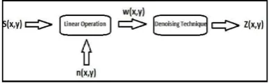
3. DE-NOISING
The image s(x, y) is blurred through a linear operation and noise n(x, y) is taken to distort the image w(x, y). w(x, y) is then folded with its restoration procedure g(x, y) to create the restored image z(x, y).
The “Linear operation” shown in Figure 1 referred as summation or multiplication of the Noise n(x, y) to their signal or image s(x, y). Once the corrupted or noised image w(x, y) is taken, then there is the application of de-noising method i.e. algorithm to obtain the de-noised image z(x, y). Noise reduction or noise removal are implemented through filtering, with the help of wavelet analysis, or by multi fractal analysis. Each technique have some advantages and disadvantages. Wavelet methods consider thresholdingat that time multifractal analysis is depended on enhancing the Holder regularity of the corrupted image.
4. FILTERING
Noise filtering is used to filter the unwanted information from an image. It is necessary to eradicate several types of noises from those images. Mostly this feature is interactive. Various filters like low pass, high pass, mean, median etc., are available.
4.1. Linear Filtering
4.1.1. Mean Filtering
A mean filter (Gonzalez and Woods, 1992) works on an image
through smoothing it, i.e., it decrease the intensity changes in between adjacent pixels. The mean filter define as a general sliding window spatial filter which exchanges the center value in that window with their average of the entire neighboring pixel values including itself. It is implemented on the basis of digital convolution using linear filters, which offers a result which is a weighted sum of their values of a pixel and their neighbors. It is also known as a linear filter. The mask or kernel refers as square. If the sum of the coefficients of the mask is one, after that the average brightness of the image is not altered. If the sum of coefficients is zero, then the average brightness has gone, and dark image is obtained in returns.
4.1.2. LMS Adaptive Filter
The variation in between the mean filter and the adaptive filter
(BhabatoshChanda and DwijeshDuttaMajumder) is referred as
weight matrix varies after single iteration in the adaptive filter at that time it remains same throughout the iterations in that mean filter. Adaptive filters have the potential for de-noising non-stationary images, i.e., images that have abrupt changes in intensity. An adaptive filter iteratively modify its parameters at the time of scanning the image to cope up with the image generating mechanism.
4.2.Non Linear Filter
4.2.1. Median Filter
The Median Filter (MF) is a non linear digital filtering
technique. Median filtering (James C. Church et al., 2008)
[image:2.595.66.263.702.762.2]conserves edges at the time of removing noise. The ultimate idea of the median filter is to replace each entry with its median of their neighboring entries. If the window has an odd value of entries, then the median becomes easy to express: it is taken as the middle value after overall entries in the window
are being sorted numerically. For some even number of entries, more than one possible median is present. Median filters are widely used as smoothers for image processing, as well as in signal processing and time series processing. The output y of the median filter at the moment t is calculated as the median of the input values corresponding to the moments adjacent to t:
y(t) = median ((x(t-T/2), x(t-T1+1),…, x(t),…, x(t
+T/2))………(1)
4.2.2. FUZZY FILTER
Fuzzy Filter (FF) is based on gray level mapping into a fuzzy
plane, using a membership function
(MozammelHoqueChowdhury et al., 2007). The main motive
to create an image of high contrast as compare to the original image through giving a larg weight to that gray levels which are nearer to the mean gray level value of the image as compare to those that are far from the mean. An image f of size M x N and L gray levels are taken as an array of fuzzy singletons, each of them process a value of membership representing its degree of brightness related to few brightness levels. For an image f(x, y), we can write in the notation of fuzzy sets:
f (x, y) = U μ x y / Ix y
4.2.3. WIENER FILTER
The goal of the Wiener Filter (WF) work as to filter out noise which occurred in a signal. It is counts on a statistical work
process. The Wiener filters (Wavelet domain image de-noising
by thresholding and Wiener filtering, 2003) work processes
filtering from a distinct angle. Performance criteria of wiener filter is minimum mean square error.
5. Proposed Work
As we have already studied a number of noises and to remove them there is a quite good category of filters available as:
Pseudo Inverse Filter
Wiener Filter
Inverse Filter
Weiner Filter and many more.
But to remove maximum possible noise from the signal is not possible with any single filter. So, we have found a new approach for de noising based on multi level filtering. Our filter is a combination of:
[image:3.595.307.560.72.360.2]PSEUDO-NOISE FILTER and WIENER FILTER
Fig. 2. Pseudo noise filter and filtered image
We are arranging these filters in series to get desired output.
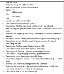
Fig. 3. Algorithm for Proposed work
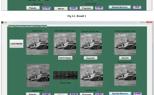
6. Simulation and Results
The selection of the denoising technique is application dependent. So, it is necessary to learn and compared enoising techniques to select the technique that is apt for the application in which we are interested. By far there is no criterion of image
quality evaluation that can be accepted generally
byall.Atechniquetocalculatethesignaltonoiseratioinimageshasb eenproposed which can be used with some approximation. This method assumes that the discontinuities in an image are only due to noise. For this reason, all the experiments are doneonanimagewithverylittlevariationinintensity.Atestimagew hereallpixel valueshavingamagnitudeof100iscreated and noise is added to it with the imnoise () function. Denoising is carried out following the techniques discussed in previous secssiona. Signal to Noise Ratio (SNR) for each of these outputs is computed.
Figures 4.1 and 4.2. The SNR of the input and out put images for the filtering approach and wavelet transform approach, respectively.
Table 1. SNR values for filtering approach
METHODS SNR OUTPUT NOISE, VARIANCE
Pseudo Inverse Filter 27.43 Salt and Pepper-0.05
Pseudo Inverse Filter 21.24 Gaussian-0.05
Wiener Filter 47.97 Salt and Pepper-0.05
Wiener Filter 22.79 Gaussian-0.05
PROPOSED FILTER 49.67 Salt and Pepper-0.05
PROPOSED FILTER 26.28 Gaussian-0.05
Speckle Remover 42.47 Speckle, 0.4
Speckle Remover 43.54 Speckle, 0.4
[image:3.595.309.558.665.755.2]From Figures 4 .1 and 4 .2, it can be seen that the mathematical results obtained from the SNR computation and the experimental results shown in the image outputs in this section only through 5 match closely. For the multi fractal denoising, the SNR computation is not compatible because, the brightness of the output image has been decreased
7. Conclusion
From the experimental and mathematical results it can be concluded that for salt and peppernoise, the median filter is
[image:4.595.44.553.52.312.2]optimal compared to mean filter and LMS adaptive filter. It produces the maximum SNR for the output image compared to the line arfilters considered. The LMS adaptive filter proves to be better than the mean filter but has more time complexity. From the output images shown in section 5, the image obtained from the median filter has no noise present in it and is close to the high quality image. The sharpness of the image is retainedun like in the case of linear filtering. In the case where an image is corrupted with Gaussian noise, the wavelet shrinkage de noising has proved to be nearly optimal. Sure Shrink produces the best SNR compared to Visu Shrink and
Fig 4.1. Result 1
[image:4.595.45.552.273.585.2]Bayes Shrink. However, the output from Bayes Shrink method is much closer to the high quality image and there is no blurring in the output image unlike the other two methods. Visu Shrink cannot de noise multiplicative noise unlike Bayes Shrink. It has been observed that Bayes Shrink is not effective for noise variance higher than 0.05. De noising salt and pepper noise using Visu Shrinkand Bayes Shrink has proved to be inefficient. When the noise characteristics of the image are unknown, de noising by multifractal analysis has proved to be the best method. It does a good job in de noising images that are highly irregular and are corrupted with noise that has a complex nature. In the two methods considered, namely multifractal regularization and multifractal pumping, the second method produces visually high quality images.
REFERENCES
BhabatoshChanda and DwijeshDuttaMajumder, Digital Image Processing and Analysis, Electronics and Communication Sciences Unit, Indian Statistical Institute, Calcutta-India. Donoho D. L. and I. M. Johnstone, Ideal spatial adaptation via
wavelet shrinkage, Biometrika, vol. 81,pp. 425–455, 1994. Gonzalez R. and R. Woods. 1992. Digital Image Processing.
Adison -Wesley, New York.
James C. Church, Yixin Chen, and Stephen V. Rice Department of Computer and Information Science, University of Mississippi, “A Spatial Median Filter for Noise Removal in Digital Images”, IEEE, page(s): 618- 623, 2008.
Jimmy Singla, "Technique Of Image Registration In Digital Image Processing - A Review", International Journal of Information Technology and Knowledge Management, Volume: 5, Pages: 239-243, July-December 2012.
KMM et al., Design and Fabrication of Color Scanner, Indian Journal of Technology, Vol 15, Apr 1997.
MozammelHoqueChowdhury M., Md. Ezharul Islam, Nasima Begum and Md. Al-Amin Bhuiyan “Digital Image Enhancement with Fuzzy Rule-Based Filtering”, IEEE,1-4244-551-9/07, 2007.
Pawar, S., P.S. Halgaonkar, J.W.Bakal, V.M.Wadhai, Implementation of PPM Image Processing and Median Filtering, IJCA, vol. 14– no.5, January 2011.
PradnyaB,Patil, Dr.Mahesh S.Chavan,”A Wavelet Based Method for Denosing of Biomedical Signal”, Proc.of the Int.Con.on Pattern recognition,Informatics And Medical Engineering,March 21-23,2012.
Sachin D Ruikar and Dharmpal D Doye, “Wavelet Based Image Denoising Technique” (IJACSA) International Journal of Advanced Computer Science and Applications, Vol. 2, March 2011.
Verma A., B.Sharma, Comparative Analysis in Medical Imaging, IJCA, vol. 1- No. 13, 2010
Wavelet domain image de-noising by thresholding and Wiener filtering. Kazubek, M. Signal Processing Letters, IEEE, Volume:10, Issue: 11, Nov. 2003 265 Vol.3.
Yun Yin, Yulettu, PeizhiLiu, ”The Research on denoising Using wavelet transform”, IEEE 2011.