Reduce Torque Ripple of IM by Approach Method DTC
Lotfi El M’Barki1,2,3, Moez Ayadi1,2,3, Rafik Neji1,2,3
1University of Sfax, Sfax, Tunisia
2Laboratory of Electronic and Information Technology (LETI), Enis, Tunisia 3Electric Vehicle and Power Electronics Group (VEEP), Enis, Tunisia E-mail: [email protected],{moez.ayadi, Rafik.neji}@enis.rnu.tn
ReceivedMay 27, 2011; revised July 6, 2011; accepted July 23, 2011
Abstract
This paper presents a new methodology for direct torque control (DTC) with improvement method control for induction motor (IM) systems. The application of approached method DTC (AMDTC), allows by using two hysteresis controllers to regulate torque and flux with the information of the angular location to address the switching table. The principal advantage of this AMDTC (optimization method of DTC) enables the minimization of the electromagnetic torque ripple and the reduction of the output current total harmonic dis-tortion (THDI). Furthermore, it improved consumption quality of IM and it improved the lifespan of the mo-tor. The switching characteristics of an inverter feeding an IM controlled with the AMDTC system are as-sessed in steady state.The proposed method of AMDTC is illustrated by computer simulations.
Keywords:AMDTC, Minimum RMS, THD, Evolution of Temperature
1. Introduction
The DTC is widely applied in industry of manufacturing and electromechanical energy utilization [1-25]. The principal advantage of AMDTC, improve the difficulty of large torque ripple and inconstant inverter switching frequency in the conventional DTC, however, many re-searchers have given attentions to these difficulty. The AMDTC of the three-phase asynchronous machine is subjected to values of the successive voltages, which realizes the protecting of its insulators of motor and ame-lioration the lifespan of IM [1,3,6-10]. Takahashi (1989) and Depenbrock (1988) have developed the DTC spe-cifically for IM [7,8]. Because the DTC was applied in 1980s for IM drives, the technique has also been used to the commands asynchronous motors. The work applica-tion of different approach DTC of asynchronous motor, allows by using two hysteresis controllers to regulate flux and torque with temperature evolution of insulated gate bipolar transistor (IGBT). The voltages of the in-verter, by using two hysteresis controllers (torque and flux), are determined by comparing between; the refer-ence flux and the estimated flux, at the same time with the reference torque and the estimated torque. The re-mainder of this article is organized as follows; principles of the proposed method in Section 2, performance en-hancement of AMDTC is discussed in Section 3, thermal
modeling of the power hybrid module is presented in Sec-tion 4, the simulaSec-tions results and discussion are dealt with in Section 5 and conclusion is presented in Section 6.
2. Principles of the Proposed Method
Generally, in the AMDTC system of IM; the equations of the three phases IM are modified in the equivalents two-phase components [1,3,4,6-9]. The equations for the IM are given by the following equations.
d d
ds ds ds V RsI
t
(1)
d d
qs qs qs
V RsI
t
(2)
d d
dr
dr dr r qr
V RrI W
t
(3)
d d
qr qr qr r dr
V RrI W
t
(4)
For squirrel-cage IM; Vdr = Vqr = 0
dds Vds RsIds
t (5)
dqs Vqs RsIqs
t
t
ddr Vdr RrIdr Wr qr
(7)
dqr Vqr RrIqr Wr dr
(8)The components, stator flux and rotor flux, are bound to the currents (stator and rotor).These fluxes are given by the following equations.
M
s L Is s Ir
(9)
M
r L Ir r Is
(10)
The absolute value and phase angle of stator flux are given by the following equation.
2 2
and arc tg qs
s ds qs
ds s
(11)
The electromagnetic torque is given by the following equation.
3
sin 2
e s s
T P I (12)
where from P = 2 is the number of pole-pairs, θ is the angle between the stator flux and stator current.
3 sin
e s s
T I (13) The electromagnetic torque is given by the following equation.
3e ds qs qs ds
T I
I
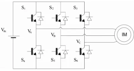
(14)From Figure 1, the voltage Vdc is the DC bus voltage,
the commands (S1, S2 and S3) are the outputs signals of
model switching table (inputs signals of IGBTs) and they are appropriate to the AMDTC strategy.
1
2
3
2 1 1 1 2 1 3
1 1 2 A dc B C V S V V S V S (15)
The commands (S1, S2, and S3) can be either 1 or 0, the
[image:2.595.319.538.462.564.2]voltage vectors d-q-0 axes are given by the following equations.
Figure 1. Three-phase voltage inverter.
1 2 31 2 3
ds DC
V V S S S
(16)
2 31 3
qs DC
V V S S
(17)3. Performance Enhancement of AMDTC
The AMDTC of Figure 2, represents three cases ((a), (b)
and (c)) of the switching frequency of IGBT to command an IM.
The switching state of the inverter is resulted from the calculated stator voltage. An AMDTC is investigated in this technique, which features in very low flux undulate and improving torque ripple with almost fixed switching frequency. This work uses an improvement torque ripple, the reduction of the THDI and optimization of consump-tion quality of IM [20,22,25]. The input reference control of the torque and input reference control of the flux are the entries of the AMDTC. One can indicate that the voltage space vector can be used via Figure 3 and by the
switches S1, S2 and S3 as follows.
0 7
2
with e ,
3
π
( 1) with 1, 2, 6
3
for 0
i
j
i D
i
V V V V
i i V V
C (18)The electromagnetic torque (Te) and stator current by
the IM; are given by following equations.
For , with
s r r s
s
s s r
r
m I
H
M
H L m
L (19) 3
sin , with
2
r
e s r
s
p m T
H s r
(20)
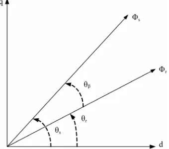
The position θβ of Figure 4, is represented the angle
difference between the rotor flux and stator flux; use a critical role in scheming output torque. Mathematically the couple is given by the following equations.
3
, with 90
2 3
, with 270
2
0, For 0 or 180
r
e s r
s
r
e s r
s e p m T H p m T H T (21)
The flux control () on Figure 5, is placed in one of
[image:2.595.98.233.488.534.2] [image:2.595.59.284.586.705.2]
φ
[image:3.595.110.509.74.475.2]→
Figure 2. AMDTC principle.
max s
min s
ref
s
Figure 5. Hysteresis control of flux.
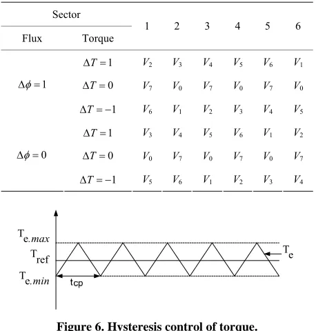
[image:3.595.137.458.83.326.2]Conforming to the approach of DTC, the information of a voltage vector is used to regulate the stator flux and torque within the limits of two hysteresis controllers (torque and flux). Allows by the output of tow hysteresis bands with the address of the angular flux location is used to data of the switching Table 1.
Figure 3. The stationary plane of inverter voltage vectors.
The proposed technique; improvements RMS of torque ripple, THD of IM and the reduction strategy con-sisted by approach method for trimming minimum of torque ripple [5] The torque and flux errors (εe, εφ), are
realized by comparing between; the reference flux and the estimated flux, at the same time with the reference torque and the estimated torque [1]. The AMDTC strat-egy is to choose the technical of better voltage vector that propels the flux magnitude (Φs) to arrive a value of
reference flux (Φref) and by the same time in turns over
flux to an adjustment corresponding to a reference torque
Tref.
Figure 4. The principle of stator flux compared to the rotor flux.
The torque control (e ) on Figure 6, is placed in one
of the four regions fixed by the following constraints.
max max
max ,
s ref
(22)
min min, min
s ref
[image:3.595.89.259.493.643.2]Table 1. Selectable seven-state voltage-vector switching table for IM control system.
Sector
Flux Torque
1 2 3 4 5 6
1 T
V2 V3 V4 V5 V6 V1
0
T
V7 V0 V7 V0 V7 V0
1
1 T
V6 V1 V2 V3 V4 V5
1
T
V3 V4 V5 V6 V1 V2
0
T
V0 V7 V0 V7 V0 V7
0
1 T
V5 V6 V1 V2 V3 V4
min . e T max . e T ref
[image:4.595.56.287.101.392.2]T Te
Figure 6. Hysteresis control of torque.
min , min min
e ref e e e
T T (25)
The AMDTC, allows to make the instantaneous torque equal with the reference torque at the end of the cycle and the technique is given by the following equation.
1
e
T k Tref (26)
The Table 2 of AMDTC represented the commuta-
tions number of switches between 0 s to 1 s. The switches commutations are recapitulated in the following Table 2.
The fluxes of the induction motor are determined by the following equation. d 1 d 0 d d S S s
S S s
s
r r r r
S r
R mr R
H H
t V
mr R R
jWr
t H L
(27)
The fluxes of (27) are expressed in the discrete form as.
1
S S
sk sk rk sk
s k
S S
R mr R
V t
H H
cp (28)
1 rk r sk r rk cp
r k
S r
mr R R
jWr t H L
(29)
where tcp is controlled period of a small value and k + 1,
the sampling instants. In our work, the root-mean-square (RMS) value of the torque ripple can be expressed as follows.
Table 2. Commutations number of switches.
AMDTC a b c
N. Commutations 1370 3600 26000
2
20 0
1 1
d d
tcp tcp
ond e
cp cp
T t Te Tref t
t t
(30)With Tond is the RMS value of the torque ripple. The
total harmonic distortion (THD) is defined as the RMS value of the current (IKRMS), divided by the RMS value of
its fundamental current (I1RMS). The quality of the current
is measured with the THDI.
2 2 1 kRMS k I RMS I THD I
(31)4. Thermal Modeling of the Power Hybrid
Module
The equivalent electrical circuit shown in [23-25] can represent the finite element method (FEM), the finite difference method (FDM) and the thermal model of the material for IGBT. The electric model used for the Se-mikron module SKM 75 GB 123 D of IGBT is used in AMDTC with a temperature without cooling; the power dissipated (Pdis), with voltage drop at the boundaries
(VCEsat(t) ) and internal resistance (RCE(Tj) ). The technique
investigation that was performed with the Semikron module SKM 75 GB 123 D (75 A/1200 V) is presented by the following equations
2 dist CE Tj c t CE Tj C t
P V I R I
T
(32)
1.5 0.002
j 25CE Tj
V (33)
0.00010 0.0275 0.00008 0.018 j CE Tj j CE Tj R T R T
(34)
5. Simulation Results and Discussion
The output voltage space vector with reduce torque rip-ple of IM by AMDTC; can be realized via switching
Table 2 and determined by the two basic variables T
and .
Because of the AMDTC, has large number of select-able voltage vectors, it benefit reduce torque and current ripples of induction motor. With Table 2, represent the
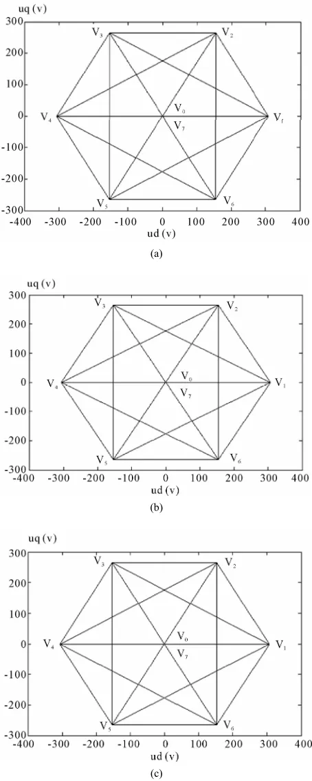
[image:4.595.58.287.104.344.2]of voltages (Vd and Vq), for AMDTC of cases ((a), (b)
and (c)).
According to results of Figure 7 for the three cases ((a),
(a)
(b)
[image:5.595.58.285.128.695.2](c)
Figure 7. The response of voltages (Vd and Vq), for AMDTC
of cases ((a), (b) and (c)).
(b) and (c)) one finds the same forms. With these ap-proaches one finds; the selection seven-state voltage- vector switching Table 1 is prepared via the Equation
(18) of inverter. One can indicate that the voltage space vector can be used via Figure 7 (Vq in function of Vd)
and by the switches (IGBTs). The voltage maximal Vq
equal 265.581 V and the voltage maximal Vd equal
306.666 V. One notices the passages enter the vectors Vj
with j = 0, 1, 2, ···, 7. Finally one notes the passages enter the vectors, one finds with each vector contains seven of possible combinations.
The output voltage of inverter via commutation switch, provoke reduce torque ripple of IM by AMDTC. Figure 8 of reference torque (60 Nm) illustrates; the
electro-magnetic torque during startup produced at 0.008 s of
(a)
(b)
[image:5.595.313.536.271.701.2](c)
Figure 8. Electromagnetic torques (Te) and reference torque
case (a), which is reduced at 0.0064 s of case (b) and case (c) the electromagnetic torque during startup at 0.0062 s. According the Figure 8, one finds the
electro-magnetic torque to follow the reference torque.
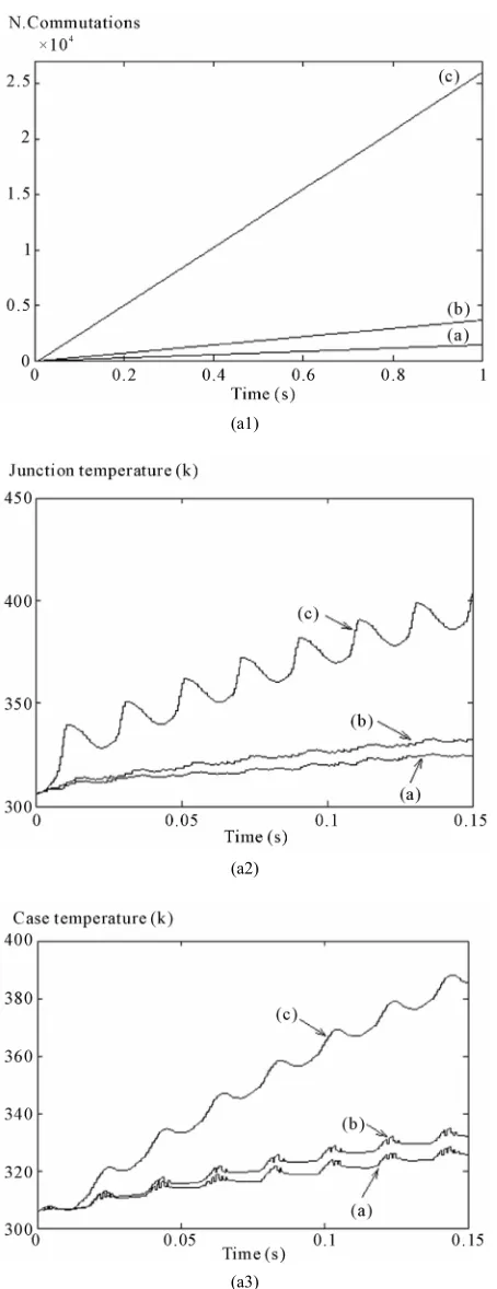
The commutations numbers of switches are realized; by 1370 of case (a), case (b) equal 3600 and case (c) equal 26000. As suggested in Figure 9, the ripples are
caused by the unbalanced output voltage, because of the AMDTC has large number of selectable voltage vectors, it benefit reduce torque ripples and current ripples of induction motor. Efficacy optimization of the IM used three proposing approaches in Figure 9 for a load of 60
Nm. For the reason of AMDTC, the voltages switching by improve torque ripple; provoke ameliorating quality of consumption IM. In Figures 9 and 10, it is noticed
that there are improved torque ripples and reduced THD. The AMDTC strategy reduces the THD in the IM. In-deed, the cases improve output current, reduces THD and current stress on semiconductors switches. By improving DTC of Figure 10(c) equal 71.88 A and the THDI is
reduced to 2.5%. The THDI is showed in Figure 10(c),
which is better THDI comparing to the current form
shown in Figures 10(a) and 10(b).
Figure 11, affirm of improving respectively the torque
ripple by the proposed AMDTC under the same IM con-dition; realized torque ripple at ±9.55 Nm of case (a), torque ripple at ±3 Nm of case (b), and torque ripple at ±
0.4 Nm of case (b), The torque ripple minimization method for AMDTC of induction motor. If compared with the cases (a) and (b), the proposed case (c) has the advantage of global minimum RMS torque ripple.
For Figure 12 (a2), the maximum junction tempera-
ture of IGBT1 at 0.15 s via approaches DTC; provoke case (a) equal 324.588 K with case (b) equal 332.296 K and case (c) equal 404.533 K. Thus the Figure 12 (a3),
represent the maximum case temperature of IGBT1 at 0.15s for Figure 12 (a3); with case (a) equal 323.654 K,
case (b) equal 332.089 K and case (c) equal 385.395 K. To consider the results of the approaches, they are nec-essary a system of temperature cooling of IGBTs.
Figures 7-12, illustrates ameliorations respectively the
torque ripples, the currents of IM and temperatures evo-lutions of three approaches scenario (a, b and c). The idea is improved the DTC by the operation of commuta-tions number and modification voltage space vector. The following Table 3 determines the results AMDTC of the
IM.
6. Conclusions
In this paper, the comparison of AMDTC strategy for approaches method (a, b and c) via advantages of Table 3 are realized; by the minimizing THD, improve torque
(a)
(b)
(c)
(a)
(b)
[image:7.595.81.264.70.706.2](c)
Figure 10. Phase currents responses and THDI of AMDTC for a load of 60 Nm.
(a)
(b)
[image:7.595.311.538.78.704.2](c)
(a1)
(a2)
[image:8.595.60.287.73.662.2](a3)
[image:8.595.310.538.93.261.2]Figure 12. Improvements for commutations and tempera-tures of AMDTC ; (a1). Commutation switches of inverter, (a2). Evolution of the junction temperature (in the IGBT1 of S1) and (a3). Evolution of the case temperature (in the IGBT1).
Table 3. The results AMDTC of the IM for a load of 60 Nm.
AMDTC a b c
Startup time (s) 0.008 0.0064 0.0062
Phase current IA(A) 73.55 72.01 71.88
THD of IA(%) 6.11 2.6 2.5
Torque ripple (Nm) 9.55 3 0.4
Reduction in torque ripple (%) Nothing 68.58 95.81
N. Commutation 1370 3600 26000 Case temperature (K) in the
IGBT1 at 0.15 s 323.654 332.089 385.395 Junction temperature (K) in the
IGBT1 at 0.15 s 324.588 332.296 404.533
ripples and thereafter improve quality of consumption IM. The proposed scenario using AMDTC enables to reduce torque ripple and obtain improvements inputs currents of IM, while guarding torque dynamic response to follow one reference torque and switching frequency to follow Figure 7. The effective of in Figures 7-12 has
been realized with different approaches ((a), (b) and (c)). We have according to the Figure 11 an approximately
95.81% reduction in torque ripple in AMDTC. The phase current with THDI of approach (c) operation contains
lowest THD to that of approaches ((a) and (b)) opera-tions. The Table 3, recapitulate advantages of the
AMDTC for the IM.
7. Acknowledgements
The authors would thank my colleagues in ENIS-Tunisia, in FSGF-Tunisia, and in ESSTT-Tunisia for the helpful support in the works.
8. References
[1] K.-K. Shyu, J.-K. Lin, V.-T. Pham, M.-J. Yang and T.-W. Wang, “Global Minimum Torque Ripple Design for Di-rect Torque Control of Induction Motor Drives,” IEEE Transactions on Industrial Electronics, Vol. 57, No. 9, 2010, pp. 3148-3156.
[2] S. Z. Chen, N. C. Cheung, K. C. Wong and J. Wu, “Inte-gral Sliding-Mode Direct Torque Control of Doubly-Fed Induction Generators Under Unbalanced Grid Voltage,” IEEE Transactions on Energy Conversion, Vol. 25, No. 2, 2010, pp. 356-368.
[3] S. B. Ozturk and H. A. Toliyat, “Direct Torque and Indi-rect Flux Control of Brushless DC Motor,” IEEE/ASME Transactions on Mechatronics, Vol. 16, No. 2, 2011, pp. 351-360.
Associated to a Variable-Speed Wind Generator,” IEEE Transactions on Energy Conversion, Vol. 25, No. 2, 2010, pp. 526-534.
[5] Y. C. Zhang and J. G. Zhu, “Direct Torque Control of Permanent Magnet Synchronous Motor with Reduced Torque Ripple and Commutation Frequency,” IEEE Transactions on Power Electronics, Vol. 26, No. 1, 2011, pp. 235-248.
[6] A. Jidin, N. R. N. Idris, A. H. M. Yatim, T. Sutikno and M. E. Elbuluk, “An Optimized Switching Strategy for Quick Dynamic Torque Control in DTC Hysteresis-Based Induc-tion Machines,” IEEE TransacInduc-tions on Industrial Elec-tronics, Vol. 58, No. 8, 2011, pp. 3391-3400.
[7] I. Takahashi and Y. Ohmori, “High Performance Torque Control of Year Induction Motor,” IEEE Transactions on Industry Applications, Vol. 25, No. 2, 1989, pp. 257-264. [8] M. Depenbrock, “Direct Self-Control (DSC) of Inverter-
Fed Induction Machine,” IEEE Transactions on Power Electronics, Vol. 3, No. 4, 1988, pp. 420-429.
doi:10.1109/63.17963
[9] B. Tabbache, A. Kheloui and M. Benbouzid, “An Adap-tive Electric Differential for Electric Vehicles Motion Stabilization,” IEEE Transactions on Vehicular Tech-nology, Vol. 60, No. 1, 2011, pp. 104-110.
[10] Z. F. Zhang, R. Y. Tang, B. D. Bai and D. X. Xie, “Novel Direct Torque Control Based on Space Vector Modula-tion with Adaptive Stator Flux Observer for InducModula-tion Motors,” IEEE Transactions on Magnetics, Vol. 46, No. 8, 2010, pp. 3133-3136.
[11] D. Casadei, F. Profumo, G. Serra and A. Tani, “FOC and DTC: Two Viable Schemes for Induction Motors Torque Control,” IEEE Transactions on Power Electronics, Vol. 17. No. 5, 2002. pp. 779-787.
doi:10.1109/TPEL.2002.802183
[12] J. A. Suul, M. Molinas and T. Undeland, “STAT-COM-Based Indirect Torque Control of Induction Ma-chines during Voltage Recovery after Grid Faults,” IEEE Transactions on Power Electronics, Vol. 25, No. 5, 2010, pp. 1240-1250. doi:10.1109/TPEL.2009.2036619
[13] R. Kumar, R. A. Gupta, S. V. Bhangale and H. Gothwal, “ANN Based Control and Estimation of Direct Torque Controlled Induction Motor Drive,” Asian Power Elec-tronics Journal, Vol. 2, No. 3, 2008, pp. 115-122. [14] H. Sudheer, S. F. Kodad and B. Sarvesh, “Torque Ripple
Reduction in Direct Torque Control of Induction Motor using Fuzzy Logic based Duty Ratio Controller,” Inter-national Journal of Electronic Engineering Research, Vol. 3, No. 1, 2011, pp. 1-12.
[15] R. Datta and V. T. Ranganathan, “Direct Power Control of Grid-Connected Wound Rotor Induction Machine without Rotor Position Sensors,” IEEE Transactions on
Power Electronics, Vol. 16, No. 3, 2001, pp. 390-399.
doi:10.1109/63.923772
[16] M. Malek, J. Vittek, V. Vavrus and M. Stulrajter, “Ap-plication of Space Vector Modulation in Direct Torque Control of PMSM,” Advances in Electrical and Elec-tronic Engineering, Vol. 7, No. 1-2, 2008, pp. 202-205. [17] Y. S. K. Babu and G. T. R. Das, “Sensorless Direct Torque
Controle of Induction Motor Using Fuzzy Controller,” ICGST-ACSE Journal, Vol. 10, No. 1, 2010, pp. 21-28. [18] X. F. Lin-Shi, F. Morel, A. M. L. B. Allard and J.-M.
Rétif, “Implementation of Hybrid Control for Motor Drives,” IEEE Transactions on Industrial Electronics, Vol. 54, No. 4, 2007, pp. 1946-1952.
[19] R. Kumar, R. A. Gupta, S. V. Bhangale and H. Gothwal, “Artficial Neural Network Based Direct Torque Controle of Induction Motor Drives,” International Conference on Information and Communication Technology in Electri-cal Sciences (ICTES 2007), Chennai, 20-22 December 2007, pp. 361-367.
[20] Y. C. Zhang, J. G. Zhu, Z. M. Zhao, W. Xu and D. G. Dorrell, “An Improved Direct Torque Control for Three- Level Inverter-Fed Induction Motor Sensorless Drive,” IEEE Transactions on Power Electronics, Vol. 21. No. 5, 2010, pp. 1-12.
[21] S. Sayeef, G. Foo and M. F. Rahman, “Rotor Position and Speed Estimation of a Variable Structure Direct-Torque- Controlled IPM Synchronous Motor Drive at Very Low Speeds Including Standstill,” IEEE Transactions on Indus-trial Electronics, Vol. 57, No. 11, 2010, pp. 3715-3723. [22] F. Khoucha, S. M. Lagoun, K. Marouani, A. Kheloui and
M. E. H. Benbouzid, “Hybrid Cascaded H-Bridge Multi-level-Inverter Induction-Motor-Drive Direct Torque Con-trol for Automotive Applications,” IEEE Transactions on Industrial Electronics, Vol. 57, No. 3, 2010, pp. 892-899.
doi:10.1109/TIE.2009.2037105
[23] M. Ayadi, M. A. Fakhfakh, M. Ghariani and R. Nej, “Electro-Thermal Simulation of a Three Phase Inverter with Cooling,” Journal of Modelling and Simulation of Systems, Vol. 1, No. 3, 2010, pp. 163-170.
[24] M. Ayadi, L. El M’barki, M. A. Fakhfakh, M. Ghariani and R. Neji, “A Comparison of PWM Strategies for Mul-tilevel Cascaded and Classical Inverters Applied to the Vectorial Control of Asynchronous Machine,” Interna-tional Review of Electrical Engineering, Vol. 5, No. 5, 2010, pp. 2106-2114.
Appendix: List of Symbols
Rs: Stator resistance (1.4534 Ω), Rr: Rotor resistance (1.4160 Ω), Lr: Rotor inductance (0.0143 H), Ls: Stator inductance (0.0144 H), M: Mutual inductance (0.0132 H),
Vds, Vqs: d-axis and q-axis stator voltages, Ids, Iqs: d-axis and q-axis stator currents,
2
1 Lr LsM : Blondel coefficient,
Φr: Rotor Flux,
Φs: Stator flux,
Tr: Load of torque (60 Nm), Te: Electromagnetic torque, Tref: Reference torque,
F: Friction coefficient (0.015 kg·m2/s), J: Moment of inertia (0.30 kg·m2), p: Number of pole pairs in the motor (2),
f: Fundamental frequency (50 Hz),
Vdc: Continuous tension (460 V), tsp: Small control period,