©IJRASET: All Rights are Reserved
942
Evaluation of Seismic Performance of Multistoried
R.C. Framed Floating Column Structures with
Lateral Force Resisting Systems
Shilpa S1, Dr. B S Jayashankar Babu2
1
M.Tech Student, Computer Aided Design of Structures, Department of Civil Engineering, PES College of Engineering, Mandya, Karnataka
2
Professor, Department of Civil Engineering, PES College of Engineering, Mandya, Karnataka,
Abstract: In modern multi-storey construction building with floating column is a typical feature. This type of structure helps in providing column free space for assembly hall and parking areas. But these features are hazardous in seismically active regions. In this paper, different locations of floating column models are considered to study the performance of a multi storey building and comparisons are made with infill frame models, infill frame having shear wall, steel bracing and infill strut at ground floor by equivalent static analysis using ETABS 2015 software. The structure was assumed to be located in seismic zone V on a medium soil.
The response of a building such as maximum storey displacement, storey drift, storey shear and fundamental time period are evaluated. From this study it can be concluded that infill strut with shear wall model shows better performance than other models.
Keywords: Floating Columns, infill as a diagonal strut, bracings, shear wall, Equivalent static analysis, storey displacement, storey drift, storey shear, time period, ETABS 2015.
I. INTRODUCTION
A. General
Earthquake is a natural phenomenon which causes vigorous shaking of earth surface. Extreme strain energy released during an earthquake travels as seismic waves for longer distances before losing its whole energy, at the point when these seismic waves reaches the ground surface sets ground in motion and this type of overwhelming forces vastly affects the building and finally leads to damage and collapse of the building. The principle causes of damage to RC buildings are floating columns, vertical geometric irregularities, plan irregularity, soft storey, inadequate ductile detailing of members, poor quality of construction material and corrosion of reinforcement. A structure having Floating Column can be classified as vertically irregular as it causes irregular distribution of mass, strength and stiffness along the building height. In most of the situations buildings become vertical irregular at planning stage itself due to some architectural and functional reasons but this features are undesirable in high seismic prone areas, hence this type of construction should be avoided, if it is unavoidable then the effect should be minimized by introducing lateral force resisting system like bracing, shear wall and infill walls to the structure.
B. Floating Column
©IJRASET: All Rights are Reserved
943
C. Masonry Infill wall
The masonry infill walls are modelled as equivalent diagonal strut. The effective width of equivalent diagonal strut is given by
w = 0.175d (λ h)-0.4
d =√ h2inf +L2inf
λ= [(Emtsin2θ)/(4EcIchinf)]1/4
Fig.1: Effective width of masonry infill wall
Where,
w= width of equivalent diagonal strut
λ= Co-efficient to determine equivalent width of infill t= Thickness of masonry infill wall.
h=Height of column between beam centerline hinf = Height of infill.
Linf = length of infill.
θ = tan-1(h/Lw)
d= Diagonal length of masonry infill. Em= modulus of elasticity of masonry infill.
Ec= Modulus of elasticity of concrete.
Ic=Moment of inertia of the column.
D. Objectives of the Study
1) To study and compare the effect of different locations of floating column in a multi-storey building.
2) To study the performance of different locations of floating column models with lateral force resisting systems such as infill as a diagonal strut, X bracings and shear wall.
3) To evaluate the parameters such as storey displacement, storey drift, storey shear and time period using ETABS software.
II. REVIEW
Bhavya B.S et al [1](2016), carried out the seismic evaluation of RC unsymmetrical building with floating column and soft storey considering different configuration. Commercial building comprising of G+7 has been selected for carrying out the project work. The building was modelled as per plan and the plan was remodified in different ways so that twelve Models are carried out in this study. The analysis is done by equivalent static method and response spectrum method using ETABS software. The structure was assumed to situated in earthquake Zone 3 and 5 on a medium soil. To improve the seismic performance infill, bracings and shear wall are introduced in the building. The parameters evaluated were displacement, storey drift, storey shear and storey stiffness of all Models are compared. The results obtained from analysis indicate that building with floating column shows poor performance during earthquake. Storey displacement increases from lower zone to higher zone. The drift and the strength demand in the first storey columns are very large for building with soft storeys. On comparison of the results obtained for each Model, it is observed that building with shear wall is much preferable when compared with other recommendations.
©IJRASET: All Rights are Reserved
944
Patil et al [3] (2015), have carried out static method, response spectrum method and time history method using ETABS-2013 Software, for the analysis of G+5 story RCC structure with considering three different models such as normal building without floating column, floating column building with shear wall and floating column building with masonry infill walls. By evaluating and comparing the results such as storey drift, storey shear and displacement of different models it is concluded that building with shear wall shows better performance when compared with other models.Er.AshfiRahaman et al[4](2015), studied the effect of floating columns on seismic response of multi-storeyed R.C framed building by static analysis and dynamic analysis using response spectrum method. The analysis is carried out using STAAD Pro software. Different cases of the building are studied by varying the locations of floating columns floor wise and within the floor. The structural response of the building Models with respect to Fundamental time period, spectral acceleration, Base shear, storey displacement, and storey drift is investigated. It is observed that in building with floating column there is an increase in fundamental time period as compared to building without floating column. By introducing floating column in a building base shear and spectral acceleration decreases. it was also observed that deflections increases marginally in that storey where floating column are located. A.P.Mundada et al[5] (2014), have carried out equivalent static analysis on existing residential building of G+7story, using STAAD Pro software. Comparison are between multistorey building with floating column and without floating column. In this work, architectural drawing and framing drawing of the building having floating column and Various effects due to floating column and load distribution on floating column has been studied. And the effects due to line of action of force and its importance is also has been studied. By comparing the results such as moments in X and Z directions, column shear at different floors and deflection at each floor. It is concluded that the probability of failure with floating column is more than the floating column with strut and deflection is greater in case of floating column than the deflection in floating column with struts.
III.METHODOLOGY
A building model of G+10 storey with different locations of floating columns and with different lateral force resisting systems has been modelled in ETABS software and considered for the present study.
A. Geometrical modelling
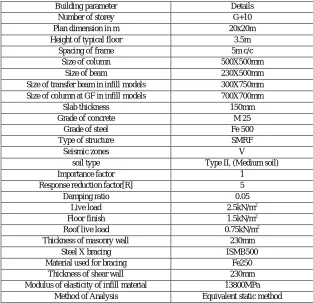
[image:3.612.149.462.428.731.2]The table 1 shows the details of the model used for the analysis.
Table 1: Details of building models
Building parameter Details
Number of storey G+10
Plan dimension in m 20x20m
Height of typical floor 3.5m
Spacing of frame 5m c/c
Size of column 500X500mm
Size of beam 230X500mm
Size of transfer beam in infill models 300X750mm
Size of column at GF in infill models 700X700mm
Slab thickness 150mm
Grade of concrete M 25
Grade of steel Fe 500
Type of structure SMRF
Seismic zones V
soil type Type II, (Medium soil)
Importance factor 1
Response reduction factor[R] 5
Damping ratio 0.05
Live load 2.5kN/m2
Floor finish 1.5kN/m2
Roof live load 0.75kN/m2
Thickness of masonry wall 230mm
Steel X bracing ISMB500
Material used for bracing Fe250
Thickness of shear wall 230mm
Modulus of elasticity of infill material 13800MPa
©IJRASET: All Rights are Reserved
945
B. Description of models
1) Model 1 - Bare frame model having floating column at the corner of the frame
2) Model 2 - Bare frame model having floating column at the outer edges of the frame
3) Model 3 - Bare frame model having floating column at the interior of the frame
4) Model 1A - Building model same as model 1, with infill strut at top storey except GF
5) Model 1B - Building model same as Model 1A, with Steel X bracing at GF
6) Model 1C - Building model same as Model1A, with shear wall at GF
7) Model 1D - Building model same as Model 1A, with infill strut at GF
8) Model 2A - Building model same as Model 2, with infill strut at top storey except GF.
9) Model 2B - Building model same as model 2A, with Steel X bracing at GF
10) Model 2C- Building model same as model 2A, with Shear wall at GF
11) Model 2D - Building model same as model 2A, with infill strut at GF
12) Model 3A - Building model same as model 3, with infill strut at top storey except GF
13) Model 3B - Building model same as model 3A, with Steel X bracing at GF
14) Model 3C - Building model same as model 3A, with Shear wall at GF
15) Model 3D - Building model same as model 3A, with infill strut at GF
Fig.2: Plan of Model 1 Fig3: Elevation of Model1A Fig.4: 3D of model-1B Fig. 5: 3D of Model-1C Fig. 6: 3D of Model -1D
©IJRASET: All Rights are Reserved
946
Fig.12: Plan of Model 3 Fig13: Elevation of Model 3A Fig.14: 3D of model 3B Fig. 15: 3D of Model 3C Fig. 16: 3D of Model-3D
IV.RESULTSANDDISCUSSION
The analysis results such as Storey displacement, storey drift, storey shear and time period are obtained from Equivalent static analysis using ETABS software are tabulated. And they are compared for different locations of floating column with lateral force resisting systems.
[image:5.612.77.535.331.518.2]A. Storey Displacement
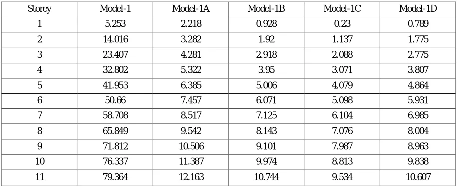
Table 2: Storey Displacement of Model-1 with Lateral Force Resisting Systems
Storey Model-1 Model-1A Model-1B Model-1C Model-1D
1 5.253 2.218 0.928 0.23 0.789
2 14.016 3.282 1.92 1.137 1.775
3 23.407 4.281 2.918 2.088 2.775
4 32.802 5.322 3.95 3.071 3.807
5 41.953 6.385 5.006 4.079 4.864
6 50.66 7.457 6.071 5.098 5.931
7 58.708 8.517 7.125 6.104 6.985
8 65.849 9.542 8.143 7.076 8.004
9 71.812 10.506 9.101 7.987 8.963
10 76.337 11.387 9.974 8.813 9.838
11 79.364 12.163 10.744 9.534 10.607
Table 3: Storey Displacement of Model-2 with Lateral Force Resisting Systems
Storey Model-2 Model-2A Model-2B Model-2C Model-2D
1 5.984 2.547 0.915 0.192 0.761
2 14.594 3.319 1.627 0.878 1.468
3 23.733 4.152 2.464 1.724 2.308
4 32.861 5.089 3.397 2.661 3.242
5 41.744 6.08 4.385 3.654 4.233
6 50.185 7.096 5.398 4.673 5.248
7 57.969 8.109 6.409 5.688 6.261
8 64.85 9.092 7.389 6.673 7.243
9 70.554 10.017 8.311 7.601 8.167
10 74.821 10.86 9.151 8.444 9.009
[image:5.612.81.537.544.697.2]©IJRASET: All Rights are Reserved
947
Table 4: Storey Displacement of Model-3 with Lateral Force Resisting SystemsStorey Model-3 Model-3A Model-3B Model-3C Model-3D
1 4.419 2.1 0.88 0.211 0.748
2 11.393 2.801 1.528 0.784 1.391
3 19.791 3.521 2.256 1.479 2.121
4 28.374 4.33 3.063 2.25 2.929
5 36.752 5.185 3.917 3.073 3.784
6 44.699 6.064 4.794 3.92 4.663
7 51.989 6.939 5.667 4.763 5.537
8 58.372 7.783 6.51 5.577 6.381
9 63.572 8.57 7.295 6.332 7.167
10 67.327 9.274 7.997 7.005 7.871
11 69.57 9.874 8.596 7.572 8.47
Fig.17: Storey displacement of model 1 with lateral force resisting systems
Fig.18: Storey displacement of model 2 with lateral force resisting systems
0 10 20 30 40 50 60 70 80 90
1 2 3 4 5 6 7 8 9 10 11
D
is
p
la
c
e
m
e
n
t
in
m
m
Storeys
STOREY DISPLACEMENT(mm)
Model-1 Model-1A Model-1B Model-1C Model-1D
0 10 20 30 40 50 60 70 80 90
1 2 3 4 5 6 7 8 9 10 11
D
is
p
la
c
e
m
e
n
t
in
m
m
Storey
STOREY DISPLACEMENT(MM)
©IJRASET: All Rights are Reserved
948
Fig.19: Storey displacement of model 3 with lateral force resisting systemsFigure 17,18 and 19 shows the storey displacement of different locations bare frame floating column models with different infill strut models. Model-1, Model-2 and Model-3 shows very large displacement. Provision of infill strut into floating column models reduces the displacement to a greater extent. Model-1A, model-2A, Model-3A shows 84.67%, 85.05% and 85.8% lesser displacement than Model-1,model-2 and model -3 respectively. Infill strut model with shear wall at ground floor shows 89.5% lesser displacement with respect to Bare frame floating column model, and infill with steel bracing and infill strut at ground floor shows 87% reduction in displacement than bare frame floating column models.
[image:7.612.76.535.346.514.2]B. Storey Drift
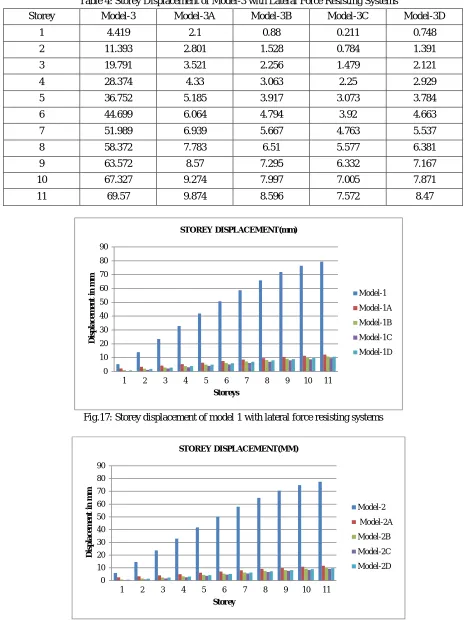
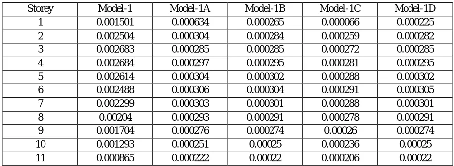
Table 5: Storey drift of Model-1 with Lateral Force Resisting Systems
Storey Model-1 Model-1A Model-1B Model-1C Model-1D
1 0.001501 0.000634 0.000265 0.000066 0.000225
2 0.002504 0.000304 0.000284 0.000259 0.000282
3 0.002683 0.000285 0.000285 0.000272 0.000285
4 0.002684 0.000297 0.000295 0.000281 0.000295
5 0.002614 0.000304 0.000302 0.000288 0.000302
6 0.002488 0.000306 0.000304 0.000291 0.000305
7 0.002299 0.000303 0.000301 0.000288 0.000301
8 0.00204 0.000293 0.000291 0.000278 0.000291
9 0.001704 0.000276 0.000274 0.00026 0.000274
10 0.001293 0.000251 0.00025 0.000236 0.00025
[image:7.612.77.534.538.730.2]11 0.000865 0.000222 0.00022 0.000206 0.00022
Table 6: Storey Drift of Model-2 with Lateral Force Resisting Systems
Storey Model-2 Model-2A Model-2B Model-2C Model-2D
1 0.00171 0.000728 0.000262 0.000055 0.000217
2 0.00246 0.000221 0.000203 0.000196 0.000202
3 0.002611 0.000238 0.000239 0.000242 0.00024
4 0.002608 0.000268 0.000266 0.000268 0.000267
5 0.002538 0.000283 0.000282 0.000284 0.000283
6 0.002412 0.00029 0.00029 0.000291 0.00029
7 0.002224 0.000289 0.000289 0.00029 0.000289
8 0.001966 0.000281 0.00028 0.000281 0.000281
9 0.00163 0.000264 0.000264 0.000265 0.000264
10 0.001219 0.000241 0.00024 0.000241 0.00024
11 0.000791 0.000211 0.00021 0.000211 0.000211
0 20 40 60 80
1 2 3 4 5 6 7 8 9 10 11
D
is
p
la
c
e
m
e
n
t
in
m
m
Storeys
STOREY DISPLACEMENT(mm)
Model-3 Model-3A Model-3B
©IJRASET: All Rights are Reserved
949
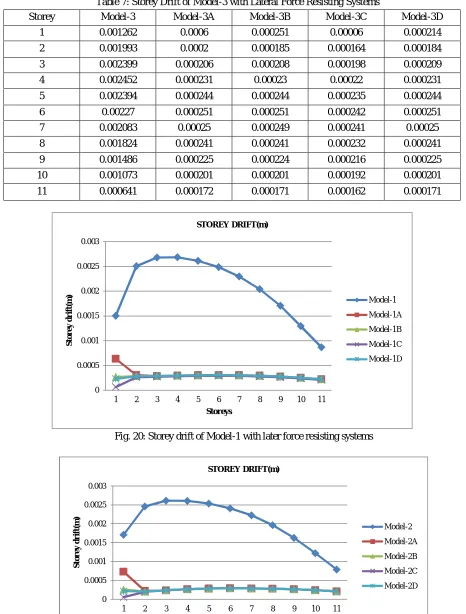
Table 7: Storey Drift of Model-3 with Lateral Force Resisting SystemsStorey Model-3 Model-3A Model-3B Model-3C Model-3D
1 0.001262 0.0006 0.000251 0.00006 0.000214
2 0.001993 0.0002 0.000185 0.000164 0.000184
3 0.002399 0.000206 0.000208 0.000198 0.000209
4 0.002452 0.000231 0.00023 0.00022 0.000231
5 0.002394 0.000244 0.000244 0.000235 0.000244
6 0.00227 0.000251 0.000251 0.000242 0.000251
7 0.002083 0.00025 0.000249 0.000241 0.00025
8 0.001824 0.000241 0.000241 0.000232 0.000241
9 0.001486 0.000225 0.000224 0.000216 0.000225
10 0.001073 0.000201 0.000201 0.000192 0.000201
11 0.000641 0.000172 0.000171 0.000162 0.000171
Fig. 20: Storey drift of Model-1 with later force resisting systems
Fig. 21: Storey Drift of Model-2 with lateral force resisting systems
0 0.0005 0.001 0.0015 0.002 0.0025 0.003
1 2 3 4 5 6 7 8 9 10 11
S
to
r
e
y
d
r
ift(m
)
Storeys
STOREY DRIFT(m)
Model-1 Model-1A Model-1B
Model-1C Model-1D
0 0.0005 0.001 0.0015 0.002 0.0025 0.003
1 2 3 4 5 6 7 8 9 10 11
S
to
r
e
y
d
r
ift(m
)
Storeys
STOREY DRIFT(m)
Model-2
©IJRASET: All Rights are Reserved
950
Fig. 22: Storey Drift of Model-3 with lateral force resisting systemsFigure 20,21 and 22 shows the variations of storey drift for bare frame floating column models and for different infill strut floating column models. It is observed that, bare frame floating column model shows maximum drift at fourth storey level. Infill floating column model shows maximum drift at first storey level, among different infill strut models, infill strut with shear wall at ground floor has least storey drift.The storey drift of infill strut models has been reduced to 76.37% than bare frame floating column models, and infill strut with shear wall shows 89% lesser drift than bare frame floating column models. infill strut with Steel bracing and infill strut at ground floor exhibits 88% reduced drift than bare frame floating column models.
[image:9.612.51.538.368.730.2]C. Storey Shear
Table 7: Storey Shear of Model-1 with Lateral Force Resisting Systems
Storey Model-1 Model-1A Model-1B Model-1C Model-1D
1 2310.3061 4057.3451 4061.2901 4095.4851 4071.6577
2 2305.4331 4048.7081 4052.5544 4085.8875 4062.6621
3 2285.7218 4013.8303 4017.6435 4050.6894 4027.6641
4 2241.3713 3935.3553 3939.0939 3971.4938 3948.9186
5 2162.5261 3795.8442 3799.4502 3830.7015 3808.9266
6 2039.3304 3577.858 3581.257 3610.7135 3590.1892
7 1861.9286 3263.9579 3267.0587 3293.9309 3275.2072
8 1620.4651 2836.705 2839.3999 2862.7545 2846.4818
9 1305.0841 2278.6604 2280.8252 2299.5854 2286.5139
10 905.9301 1572.3852 1573.879 1586.8245 1577.8045
11 413.1474 700.4405 701.106 706.8727 702.8546
Table 8: Storey Shear of Model-2 with Lateral Force Resisting Systems
Storey Model-2 Model-2A Model-2B Model-2C Model-2D
1 2308.2633 4060.439 4064.3839 4098.579 4074.7516
2 2303.441 4051.7246 4055.5708 4088.9027 4065.6781
3 2283.7468 4016.8209 4020.6339 4053.6787 4030.6541
4 2239.4346 3938.2874 3942.0259 3974.4246 3951.8502
5 2160.6575 3798.6723 3802.2782 3833.5284 3811.7543
6 2037.5683 3580.5237 3583.9226 3613.3781 3592.8544
7 1860.3198 3266.3897 3269.4904 3296.3617 3277.6387
8 1619.0649 2838.8185 2841.5133 2864.8671 2848.5949
9 1303.9565 2280.3581 2282.5228 2301.2824 2288.2113
10 905.1474 1573.5567 1575.0505 1587.9955 1578.9758
11 412.7904 700.9624 701.6278 707.3943 703.3764
0 0.0005 0.001 0.0015 0.002 0.0025 0.003
1 2 3 4 5 6 7 8 9 10 11
S
to
r
e
y
d
r
ift(m
)
Storeys
STOREY DRIFT(m)
Model-3 Model-3A Model-3B
[image:9.612.77.532.544.734.2]©IJRASET: All Rights are Reserved
951
Table 9: Storey Shear of Model-3 with Lateral Force Resisting SystemsStorey Model-3 Model-3A Model-3B Model-3C Model-3D
1 2323.9085 4067.8017 4071.7466 4105.9417 4082.1142
2 2318.6958 4058.9029 4062.7487 4096.0779 4072.8552
3 2298.8711 4023.9373 4027.75 4060.792 4037.7694
4 2254.2655 3945.2646 3949.0028 3981.3988 3958.8263
5 2174.9667 3805.4022 3809.0078 3840.2554 3818.4831
6 2051.0623 3586.8671 3590.2657 3619.7188 3599.1968
7 1872.6399 3272.1766 3275.2771 3302.1461 3283.4246
8 1629.7873 2843.8479 2846.5425 2869.8944 2853.6235
9 1312.592 2284.3981 2286.5626 2305.3207 2292.2507
10 911.1418 1576.3445 1577.8381 1590.7821 1581.7632
[image:10.612.140.498.535.714.2]11 415.5242 702.2043 702.8696 708.6357 704.6181
Fig. 24: Storey shear of Model-1 with lateral force resisting systems
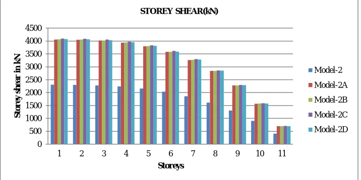
Fig. 23: Storey shear of Model-2 with lateral force resisting systems
0 500 1000 1500 2000 2500 3000 3500 4000 4500
1 2 3 4 5 6 7 8 9 10 11
S
to
r
e
y
s
h
e
a
r
in
k
N
Storeys
STOREY SHEAR(kN)
Model-1 Model-1A
Model-1B Model-1C Model-1D
0 500 1000 1500 2000 2500 3000 3500 4000 4500
1 2 3 4 5 6 7 8 9 10 11
S
to
r
e
y
s
h
e
a
r
i
n
k
N
Storeys
STOREY SHEAR(kN)
Model-2 Model-2A Model-2B
©IJRASET: All Rights are Reserved
952
Fig. 25: Storey shear of Model-3 with lateral force resisting systemsFigure 23,24 and 25 shows the storey shear for different floating column and infill strut models. it is observed that storey shear is maximum for infill strut models than bare frame floating column models. infill strut shows 69% larger shear force than bare frame floating column models, infill strut with shear wall at GF shows 71% larger shear than bare frame floating columns and infill strut with steel bracing and infill strut at GF displays 70% larger shear force than bare frame floating column models.
[image:11.612.75.539.407.668.2]D. Fundamental Time Period
Table 8: Tie period of different location floating column models with Lateral Force Resisting Systems
Models Bare frame FC
model Model-A Model-B Model-C Model-D
Model-1 2.002 0.638 0.578 0.531 0.571
Model-2 1.992 0.626 0.548 0.514 0.541
Model-3 1.873 0.578 0.515 0.469 0.508
Fig. 27: Fundamental time period of different location floating column with lateral force resisting systems
Figure 27 shows the time period values for different bare frame floating column models and different infill models, from the figure it is seen that bare frame floating column models have longest period than infill strut models. Infill strut with shear wall at ground floor shows least time period value than other infill strut models.
0 500 1000 1500 2000 2500 3000 3500 4000 4500
1 2 3 4 5 6 7 8 9 10 11
S
to
r
e
y
s
h
e
a
r
i
n
k
N
Storeys STOREY SHEAR(kN)
Model-3 Model-3A
Model-3B Model-3C Model-3D
0 0.5 1 1.5 2 2.5
Model-1 Model-2 Model-3
ti
m
e
p
e
r
io
d
i
n
s
e
c
o
n
d
s
models
FUNDAMENTAL TIME PERIOD
Bare frame FC Model Model-A
©IJRASET: All Rights are Reserved
953
V. CONCLUSIONSBy comparing the analysis results following conclusion are made:
A. Model-1 shows maximum displacement than Model-2 and model-3.Introducing infill strut into different locations floating column models largely reduces the displacements. Infill strut model with shear wall at ground floor has least displacement.
B. Bare frame floating column shows maximum drift and it is observed at fourth storey level, for infill strut, maximum storey drift was observed at first storey level due to reduction of stiffness. Among different infill strut models infill with shear wall shows least drift.
C. Storey shear is more at the base and it gradually decreases from bottom storey to top storey in all the models.
D. Infill strut models shows increased shear force than bare frame floating column models.
E. Bare frame floating column models shows more time period than infill strut models.
F. Among different models such as infill strut, infill strut with shear wall, steel bracing and infill at ground floor level, shear wall models shows better performance.
REFERENCES
[1] A.P.Mundada, and S.G.Sawdarkar, (2014), “Comparative Seismic Analysis of Multistory Building with and without Floating Column”, International Journal of Current Engineering and Technology, E-ISSN 2277-4106,P-ISSN 237-5161
.
[2] Prof.SaritaSingla, Er. AshlieRahaman, (2015), “Effect of Floating Columns on Seismic Response of Multi-storied RC framed Buildings”, International Journal of Engineering Research and Technology (IJERT),ISSN:2278-0181,Vol.4 Issue 06
.
[3] Isha Rohilla,S.M. gupta,Babitasaini,(2015),“Seismic Response of Multi-storey Irregular Building with Floating Column”, International Journal of Research in Engineering and Technology,Volume 04,Issue03.
[4] Umesh P.Patil,Shivanand S Hallur,(2015), ,“Seismic Analysis of G+5 Framed Structure with and Without Floating Columns Using ETABS-2013 Software”, International Research Journal of Engineering and Technology,Volume02,Issue 04.
[5] Bhavya B.S and Jisha P,(2016), “Seismic evaluation of RC unsymmetrical building with floating columns and soft storey considering different configuration”, International Journal of Innovative Research in Science, Engineering and Technology,Vol.5,pp.15456-15465.
[6] IS: 1893(part-1)-2002 Code of Practice for criteria for Earthquake Resistant Design of structures, part – 1: General provisions and buildings, Bureau of Indian standards, New Delhi.
[7] IS: 875-1987 – Code of practice for Design Loads (other than Earthquake) for Building and Structures, Part 1: Dead loads, Part – 2: Imposed loads, Part – 5: Special loads and load combinations, Bureau of Indian Standards, New Delhi.