ISSN Online: 1947-3818 ISSN Print: 1949-243X
Permanent Fault Identification Method for
Single-Phasea Adaptive Reclosure of UHVAC
Transmission Line
Duanqiang Du
1*, Chunming Li
2, Jinwei Zhang
11College of Electrical Power, Inner Mongolia University of Technology, Huhhot, China 2College of Information Engineering, Inner Mongolia University of Technology, Huhhot, China
Abstract
In order to avoid the UHVAC (Ultra High Voltage Alternating Current) transmission line with shunt reactor fault voltage smaller problems, through the analysis of single-phase permanent fault when tripping phase terminal voltage characteristics, this paper presents a fault phase voltage signal of the two order derivative and the original signal ratio of a new method for steady- state frequency discrimination single-phase permanent fault. The principle of this method is simple, and it can avoid the problem that the fault voltage caused by the installation of shunt reactor is small. The adaptability and cor-rectness of the proposed method are verified by a large number of simula-tions.
Keywords
Adaptive Reclosure, Permanent Fault, Steady State Component Frequency
1. Introduction
Most faults in UHVAC transmission system are single phase transient fault [1]. In the traditional automatic re-lock, if the coincidence of permanent fault, the system will cause the two shock, and even make the system crash. In 1980s, Pro-fessor Ge Yaozhong put forward the idea of “adaptive reclosure” [2] arousing wide attention of experts and scholars in electrical engineering from domestic and foreign. A wealth of achievements have been made in the study of the two arc characteristics [3], the voltage characteristics [4] [5], the current characteris-tics of shunt reactor [6] [7] [8] and the characteristic of model parameters [9] [10]. The practical application is difficult since neural network based on the need to train a large number of samples [11] [12]. The criterion based on arc criterion How to cite this paper: Du, D.Q., Li, C.M.
and Zhang, J.W. (2017) Permanent Fault Identification Method for Single-Phasea Adaptive Reclosure of UHVAC Transmis-sion Line. Energy and Power Engineering, 9, 149-154.
https://doi.org/10.4236/epe.2017.94B018
and voltage is difficult to realize since the shunt reactor technology is widely used in the super high voltage, which accelerates the arc quenching process and limits the amplitude of the fault voltage [13].
Based on the analysis of the characteristic of single-phase permanent fault phase voltage after tripping ,this paper proposes method for distinguishing sin-gle phase permanent fault based on steady-state component frequency acquired through two order derivative of the fault phase voltage signal and the ratio of the original signal.
2. Analysis on the Characteristics of Fault Phase
Voltage during Single-Phase Permanent Fault after
Tripping
During the single-phase permanent fault, fault phase voltages U t( ) is com-posed of the steady state component and the transient component, the expres-sion was as follows:
1 1 1 2 2 2
( ) sin( ) t sin( )
U t =U ωt+ϕ +e−βU ω t+ϕ (1)
In the formula: U1, ω1, ϕ1 represent voltage amplitude, frequency and
phase steady components respectively, U2, ω2, ϕ2 represent the amplitude,
frequency and phase of transient component respectively, β is transient at-tenuation coefficient.
Due to the fault point to ground reliable discharge, the transient component will decay rapidly to zero, after entering the steady state, its expression is:
1 1 1
( ) sin( )
U t =U ωt+ϕ (2)
After two order derivative of the formula (2):
'' 2
1 1 1 1
( ) sin( )
U t = −ωU ωt+ϕ (3)
and then
2 U t''( ) /U t( )
ω = − (4) So the steady state component frequency f is:
''
( ) / ( ) / (2 )
f = U t U t
π
(5)Because the steady state component is mainly determined by the sound phase capacitance coupling voltage and the electromagnetic coupling voltage [14], the steady state frequency f is close to the frequency of the power frequency f0. Based
on the above analysis, the relations between steady state component frequency and frequency as following:
0
f ≤ ⋅k f (6)
In the formula, k represents reliability coefficient. After a lot of simulation, the author found that the 1.3 is suitable in considering the line model equivalence and simplification of the simulation software, actual gap between f and f0.
3. Discriminant Principle
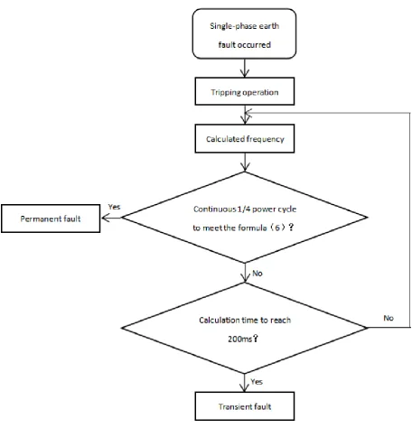
the whole cycle. Two arc durations are about 200 ms during transient fault [15]. Considering the above two aspects, this paper focuses on 200 ms time period af-ter trip and calculates the data from power system, if calculate data in 1/4 conti-nuous power frequency period satisfied formula of (5), the fault is determined as a permanent fault. Otherwise, it will be judged as instantaneous fault. Criteria flow chart is shown in Figure 1.
4. Simulation Results and Analysis
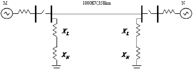
[image:3.595.82.539.248.723.2]As shown in Figure 2, the simulation model is based on the model of 1000 KV UHV line system in the southeast Nanyang. Line length is 358 km. Parameters of this line are as following:
Figure 2. Model of 1000 KV UHV transmission line system in Southeast Nanyang.
1 0 1
0 1 0
0.00758 / 0.15421 / 0.2635 /
0.8306 / 0.013970 / 0.0.009296 /
R km R km L km
L km C µF km C µF km
= Ω = Ω = Ω
= Ω = =
, ,
, ,
System parameters at both ends are:
0m 0.86 52.74
Z = + j , Z1m =0.8+ j10.89, Z0n =5.69+ j14.18,
1n 3.15 8.15
Z = + j .
Parameters of shunt reactor:
1680 / L
X = Ω km
Parameters of neutral point small reactor: 442.21 N
X = Ω.
Permanent single-phase grounding fault occurs of system in 0.5 s, tripping in 0.1 s, and the sampling frequency is 10 kHz. The calculation results show that the power angular phase difference are 0˚, 10˚, 20˚, 30˚, 40˚, 50˚ respectively, the transition resistances are corresponding to 0Ω, 50Ω, 100Ω, 200Ω, 400Ω, the fault distance is the line (from the M side) 0%, 25%, 50%, 75%, 100% cor-responding to a total of 150 cases can be accurately identified.
Table 1 and Table 2 are discriminant success time when
θ
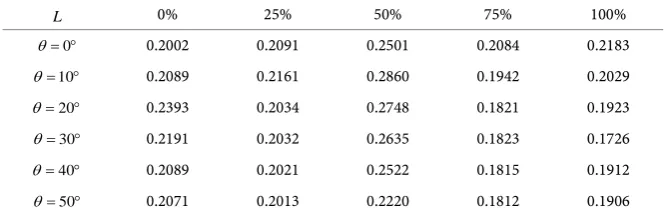
= °10 , R=100Ω. From Table 1 we can make conclusion that when the power angle difference and transition resistance are constant, discriminant success time showing such a regularity that increase first and then decrease with increasing of L. When the power angle difference and the fault location is certain, discriminant success time shows decreasing trend with increasing of R. From Table 2 we can also seen that when the fault position and the transition resistance are at a certain time, discriminant success time showing such a regularity that increase first and then decrease with increasing of θ.By a lot of simulation data can be seen that in the UHV AC transmission sys-tem in the occurrence of a permanent fault occurs, the duration of transient component is 180 ms - 55 ms after tripping.
4. Conclusions
Table 1. Criterion flow chart successful time table when θ = °10 .
L 0% 25% 50% 75% 100%
0
R= Ω 0.2435 0.2361 0.2840 0.2625 0.2729
50
R= Ω 0.2264 0.2256 0.2849 0.2143 0.2226
100
R= Ω 0.2089 0.2161 0.2860 0.1942 0.2029
200
R= Ω 0.2001 0.1974 0.2856 0.1824 0.1945
400
R= Ω 0.1724 0.1884 0.2768 0.1738 0.1840
Table 2. Successful time table when R=100Ω.
L 0% 25% 50% 75% 100%
0
θ= ° 0.2002 0.2091 0.2501 0.2084 0.2183
10
θ= ° 0.2089 0.2161 0.2860 0.1942 0.2029
20
θ= ° 0.2393 0.2034 0.2748 0.1821 0.1923
30
θ= ° 0.2191 0.2032 0.2635 0.1823 0.1726
40
θ= ° 0.2089 0.2021 0.2522 0.1815 0.1912
50
θ= ° 0.2071 0.2013 0.2220 0.1812 0.1906
fault phase voltage and the ratio of the fault phase. The method is simple, high reliability and strong adaptability, and a lot of simulation results verify that the proposed criterion is also suitable for 500 kV ultra high voltage transmission line.
The deficiency of this criterion is that:
1) Although this criterion can accurately identify the fault, the discriminant success time affected by transition resistance relatively large; 2) Due to the use of the ratio method, the denominator (fault phase voltage) may be zero, but not appear in the simulation.
References
[1] Bai, X. andZheng, W.J. andLi, G.Q.(2015) Study on Electromagnetic Transient Problem under Asymmertric Faults of EHV/UHV. Power Technolo-gy,139,1751-1751.
[2] Ge, Y.Z.(1984) Method of distinguishing between instant and permanent faults during automatic. Journal of Xi’AnJiaoTong University, 18,23-31.
https://doi.org/10.1016/j.epsr.2006.04.006
[3] Elkalashy, N.I. and Darwish, H.A. and Taalab, A.I. (2007) An Adaptive Single Pole Autoreclosure Based on Zero Sequence Power.Electric Power Systems Re-search,77,438-446.
[4] Wang, Z.P. andLiu, H.F. andXu, Y. (2006) Criterion for Determining Fault Nature in Adaptive Single-Phase Reclosing for Shunt Compensated EHV/UHV Transmis-sion lines. Power System Technology, 30, 29-34.
[5] Li, B.T. and Li, Y.L.(2009) A New Criterion for Adaptive Single Pole Au-to-Reclosureof Ehv Transmission Lines with Shunt Reactor Compensation. Auto-mation of Electric Power Systems, 33,48-54.
[image:5.595.206.539.218.325.2]the CSEE,26,75-81.
[7] Shang, L.Q. andBai, W.Z. and Cheng G. (2008) Fault Nature Identification for Sin-gle-Phase Adaptive Reclosureon Transmission Lines with Shunt Reators. Automa-tion of Electric Power Systems, 32,81-84.
[8] Suo, N.J.L. and Song, G.B. and Shao, W.Q. (2007) Identification of Permanent Faults Based on Differential Current Protection for Transmission Lines with Two Shunt Reactors. Automation of Electric Power Systems,31,56-60.
[9] Suo, N.J.L. and Shao, W.Q. andSong, G.B. (2009) Study on Single-Phase Adaptive Reclosure Scheme Based on Parameter Identification. Proceeding of the CSEE, 29,48-54.
[10]Suo, N.J.L. andJia, M.L.H. andSong, G.B.(2008) Permanent Fault Identification Me-thod Based on Capacitance Parameter.Journal of Xi’AnJiaoTong University, 42,708-712.
[11]Nie, H.Z.,Dong, S. and Li, T.Y., et al. (2005) Single-phase Adaptive Auto-Reclosure Based on Fuzzy Neural Network. Power System Technology, 29,75-79.
[12]Yang, W., Peng, L. and Zhang, J.F. (2005) ADapativeautoreclosure of Single Phase Based on FNN. Relay, 33,66-70.
[13]Wang Q.Q., Wang H.F. and Lin, D. (2015) An Identification Method of Sin-gle-Phase Permanent Fault at Transmission Lines with Shunt Reators. Automation of Electric Power Systems,39,101-106.
[14]Shao, W.Q., Zhang, X.W. and Song, J.X.(2013) Non-fault Identification Voltage and Current Based Integrated Criterion for Single-Phase Reclosure on UHVACtrans-missionLines. High Voltage Engineering, 39,546-554.
[15]Xin, L., Zhao, D.D. and Cao, L. (2016) Study on the Induced Voltage And Potential Current of UHVAC Transmission Project. Electrical Technology,2,42-46.
[16]Cheng, L., and Song, Z.L. (2010) An Approach to Identify Faults in UHV AC Transmission Line Equipped with Shunt Reactor. Power System Technolo-gy,34,216-222.
Submit or recommend next manuscript to SCIRP and we will provide best service for you:
Accepting pre-submission inquiries through Email, Facebook, LinkedIn, Twitter, etc. A wide selection of journals (inclusive of 9 subjects, more than 200 journals)
Providing 24-hour high-quality service User-friendly online submission system Fair and swift peer-review system
Efficient typesetting and proofreading procedure
Display of the result of downloads and visits, as well as the number of cited articles Maximum dissemination of your research work
Submit your manuscript at: http://papersubmission.scirp.org/