A Dissertation by
VIVEK MEENAKSHI SUNDARAM
Submitted to the Office of Graduate and Professional Studies of Texas A&M University
in partial fulfillment of the requirements for the degree of DOCTOR OF PHILOSOPHY
Chair of Committee, Hamid Toliyat Committee Members, Mehrdad Ehsani
Shankar Bhattacharyya Won-Jong Kim
Head of Department, Miroslav Begovic August 2016
Major Subject: Electrical Engineering
ABSTRACT
A motor is said to be reliable if it can run at its rated operating condition for a specified period of time. With the widespread use of electric motors in newer applications, reliability is a major concern in terms of safety as well as revenue. About 30-40% of reported failures in induction motors are due to stator faults. It is well known that a stator fault starts as an inter-turn fault within a phase and then propagates into phase-to-phase and phase-to-ground faults that can then lead to complete shutdown of the motor. Two approaches have been taken in this dissertation to make an induction motor drive system more tolerant to stator faults; integration of an inter-turn fault detection method into a five-phase induction motor drive and design of fault-tolerant induction motors.
The phase redundancy of five-phase motors makes it possible to achieve continued operation of the motor with an open phase. However, for true fault tolerance the drive must be able to detect an incipient fault and then transition to post fault operation. A low-cost diagnostic method based on DC voltage injection has been developed for detection of inter-turn faults in five-phase induction motor drive systems. It has been shown that difference in DC current response to an injected voltage before and after an inter-turn fault serves as a reliable fault indicator. The diagnostic is non-intrusive, requires no additional hardware and effectively integrates both fault detection and fault-tolerant control into the motor controller. The method has been successfully implemented and tested on low-cost microcontroller.
iii
other at the end connections. Tooth wound or fractional slot concentrated winding (FSCW) stators have non-overlapping end connections and hence more physical and thermal isolation between the phases as compared to distributed winding stators. While FSCW configurations have been widely used for permanent magnet motors, their adoption for induction motors is a challenge. An FSCW configuration has been designed for outer rotor induction motors by using a dual slot layer stator structure and multilayer windings. Comparison with a conventional induction motor shows an 11% reduction in the copper usage in addition to having non-overlapping phase windings.
v
ACKNOWLEDGEMENTS
First, I thank my advisor Dr. Hamid A. Toliyat, with whom I spent the last six years of my graduate life, for all the advice, encouragement and support he has given me throughout the course of this research. He is my role model and a source of inspiration, and I feel honored to have had to opportunity to work under him.
I thank my committee members Dr. Mehrdad Ehsani, Dr. Shankar Bhattacharyya and Dr.Won-Jong Kim for their valuable time. I have learned a lot from their courses. I thank my colleagues at the Advanced Electric Machines and Power Electronics Lab, Yateendra, Matthew Johnson, Jae-Bum, Siavash, Mahshid, Morteza, Ajay, Babak, Robert, Hussain, Hamidreza, Khaled, Abdulkadir, Amir, Niloofar, Bahar, Matthew Gardner and Yongqi. I learnt a great deal from my countless interactions with them. I also thank all my friends and roommates who made my life at Texas A&M University fun and memorable. Finally I thank my parents, my brother and my wife Suhasini who patiently supported and encouraged me throughout this endeavor.
TABLE OF CONTENTS Page ABSTRACT ... ii DEDICATION ... iv ACKNOWLEDGEMENTS ... v TABLE OF CONTENTS ... vi
LIST OF FIGURES ... viii
LIST OF TABLES ... xii
1. INTRODUCTION ... 1
1.1 Faults in Induction Motors ... 3
1.2 Stator Inter-Turn Faults Detection ... 5
1.3 Fault-Tolerant Operation ... 9
1.3.1 Control of Five-Phase Motors ... 9
1.3.2 Fault-Tolerant Operation of Five-Phase Motors ... 14
1.4 Fault-Tolerant Induction Motor Design ... 16
1.5 Problem Statement ... 21
1.6 Dissertation Outline ... 22
2. CONTROL OF FIVE-PHASE INDUCTION MOTORS ... 24
2.1 Control of Five-Phase Induction Motors Using Resonant Controllers ... 24
2.2 Fault-Tolerant Control of Five-Phase Induction Motors ... 31
2.3 Chapter Summary ... 36
3. MODELING OF INDUCTION MOTORS WITH INTER-TURN FAULTS ... 37
3.1 Generalized Model of an Induction Motor ... 37
3.2 Modeling an Inter-Turn Short Circuit ... 45
3.3 Chapter Summary ... 51
4. ON-LINE INTER-TURN FAULT DETECTION USING DC INJECTION ... 53
vii
4.5.1 Fault Detection Sensitivity ... 66
4.5.2 Effect of Controller ... 67
4.5.3 Effect of Dead-Time and Switch Non-Linearity ... 68
4.5.4. Effect of Winding Asymmetries... 72
4.5.5. Effect of Temperature ... 72
4.5.6. Effect of DC Bus Voltage ... 72
4.6 Chapter Summary ... 73
5. FSCW CONFIGURATION FOR OUTER ROTOR INDUCTION MOTORS ... 74
5.1 Stator Winding Design ... 74
5.1.1 Feasible Slot-Pole Combinations ... 74
5.1.2 Stator Winding Configuration ... 77
5.2 Dual Slot Layer Stator ... 81
5.3 Cage Rotor Design ... 83
5.4 Design Comparison ... 84
5.5 Chapter Summary ... 90
6. EXPERIMENTAL RESULTS ... 92
6.1 Details of Experimental Set-Up ... 92
6.2 Digital Implementation of the Motor Control Loop ... 92
6.2.1. Sampling ISR ... 96
6.2.2. DC Measurement ISR ... 96
6.2.3. Control ISR ... 97
6.3 Experimental Verification of Fault Detection Algorithm ... 101
6.4 Experimental Verification of Fault-Tolerant Control ... 108
7. CONCLUSIONS AND FUTURE WORK ... 111
LIST OF FIGURES
Page Figure 1. Types of stator winding faults in a three-phase motor ... 4 Figure 2. A five-phase motor driven using five leg inverter ... 10 Figure 3. Closed loop V/f control of five-phase induction motor ... 12 Figure 4. Indirect FOC of five-phase induction motor in synchronously rotating
reference frame ... 12 Figure 5. Switching states for SVPWM of a five-phase motor. ... 13 Figure 6. Three-phase inverter using a modular motor drive topology with
independent H-bridges for each phase ... 17 Figure 7. Comparison of stator windings (a) fractional slot concentrated winding
and (b) a distributed winding ... 17 Figure 8. Commercially available switched-reluctance motor ... 18 Figure 9. Harmonic equivalent circuit of an induction motor ... 19 Figure 10. Torque speed characteristics of a ½ SPP FSCW induction motor obtained
from the harmonic equivalent circuit ... 20 Figure 11. Current control loop with PR controller ... 29 Figure 12. Change in the frequency response with increasing (a) 𝐾𝑝 (b) 𝐾𝑖 ... 30 Figure 13. Complete vector control loop of five-phase induction motor with PR
controller ... 30 Figure 14. Simulation results of five-phase motor with PR controller with load
change at t = 1.5s ... 31 Figure 15. Phase shifts between the currents for fault-tolerant operation with
one phase opened ... 33 Figure 16. Phase shifts between the currents for fault-tolerant operation with
ix
Figure 17. Complete vector control loop of five-phase induction motor for
fault-tolerant control ... 35
Figure 18. Fringing of the air gap flux due to stator and rotor slotting effects ... 38
Figure 19. Different types of flux fringing between the stator and rotor teeth ... 39
Figure 20. Rotor cage modeled as individual loops ... 40
Figure 21. Five-phase star connected stator with inter-turn fault in phase A ... 45
Figure 22. Equivalent circuit of five-phase star connected motor with bolted inter-turn fault ... 47
Figure 23. Mutual inductance between the shorted turns (5.55%) and a rotor loop ... 48
Figure 24. Mutual inductance between the faulty phase and a rotor loop (a) from FEA with infinitely permeable core (b) from model ... 48
Figure 25. Phase currents for 5.55% inter-turn fault (a) model (b) FEA ... 50
Figure 26. Short circuit current for 5.55% inter-turn short (a) model (b) FEA... 50
Figure 27. Torque developed during 5.55% inter-turn fault (a) model (b) FEA ... 50
Figure 28. Flux density distribution in the presence of inter-turn short ... 51
Figure 29. Five-phase five leg inverter with resistive load ... 57
Figure 30. Average voltage applied to the phases of over a switching cycle, during DC injection across A and B ... 58
Figure 31. Five-phase star connected resistive load with DC applied across A and B .... 59
Figure 32. Five-phase star connected unbalanced load with DC applied across A and B ... 61
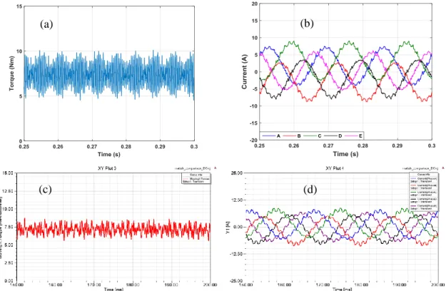
Figure 33. Torque and current waveforms with unbalanced DC injection (a) and (b) model (c) and (d) FEA ... 65
Figure 34. Torque and current waveforms with balanced DC injection (a) and (b) model (c) and (d) FEA ... 66
Figure 35. Change in the DC offset current ∆𝐼𝐷𝐶 vs slip for (a) 5.55% (b) 8.33% inter-turn fault in phase A ... 67
Figure 36. Five-phase motor control loop incorporating DC voltage injection ... 69
Figure 37. Current path during dead times for an inverter leg ... 70
Figure 38. (a) DC voltage contributed by dead time effects without application of DC offset (b) comparison of effect of current amplitude on dead-time DC voltage contribution ... 71
Figure 39. Experimental result showing change in ∆𝐼𝐷𝐶with load for the same DC voltage command ... 71
Figure 40. Star of slots for 24 slot 10 pole multi-layer configuration with uniform turns per coil. ... 78
Figure 41. (a) Air gap MMF of 24 slot 10 pole winding with uniform turns per coil and, (b) its frequency components. ... 79
Figure 42. Star of slots for 24 slot 10 pole multi-layer configuration with varying turns per coil. ... 80
Figure 43. Variation of first order sub-harmonic with x and y. ... 80
Figure 44. (a) Air gap MMF of 24 slot 10 pole winding with varying turns per coil and (b) its frequency components. ... 81
Figure 45. (a) Dual slot layer 24 slot 10 pole stator and (b) it end connections. ... 82
Figure 46. (a) Ceiling fan stator (b) non-overlapping end connections ... 83
Figure 47. Effective stack length of a stator ... 85
Figure 48. Comparison of stack lengths of (a) FSCW and (b) distributed winding for the same effective stack length. ... 86
Figure 49. (a) Air gap flux density of the FSCW and distributed winding designs from FEA and, (b) their frequency components. ... 87
Figure 50. Comparison of flux density distribution in the FSCW and distributed winding motors. ... 89
Figure 51. Instantaneous torque of the FSCW and distributed winding motors at rated slip. ... 90
Figure 52. Layout of experimental set-up ... 94
xi
Figure 56. Flowchart for DC calculation by the DSP ... 99 Figure 57. Flowchart for control ISR and Sampling ISR ... 100 Figure 58. Experimental connection of motor windings for inter-turn fault ... 102 Figure 59. Comparison of torque with balanced and unbalanced DC voltage
application (Speed =900rpm T = 5Nm) ... 103 Figure 60. Currents with balanced DC voltage application ... 103 Figure 61. Comparison of vibration measured on motor casing with (a) balanced
and (b) unbalanced DC voltage application ... 104 Figure 62. DC offset in the current in phase A before and after a 5.55% turn
fault is applied to the phase ... 105 Figure 63. ∆𝐼𝐷𝐶 after a 5.55% turn fault in phase A at 900rpm for different
loads ... 106 Figure 64. ∆𝐼𝐷𝐶 after a 5.55% turn fault in phase A at 1080rpm for different
loads ... 106 Figure 65. ∆𝐼𝐷𝐶 after a 5.55% turn fault in phase A at 1260rpm for different
loads ... 107 Figure 66. ∆𝐼𝐷𝐶 for phase A after a 5.55% turn fault in phase A calculated
by the microcontroller at random time points ... 107 Figure 67. Schematic for experimental testing of fault-tolerant operation ... 108 Figure 68. Operation of the motor under healthy condition at 900rpm ... 109 Figure 69. Operation of the motor with phase A opened using the conventional
control loop ... 109 Figure 70. Operation of the motor with phase A opened applying fault-tolerant
control ... 110 Figure 71. Transition from healthy to faulty to fault-tolerant operation ... 110
LIST OF TABLES
Page
Table 1. Space harmonic mapping ... 27
Table 2. Step harmonic amplitudes for common FSCW configurations ... 75
Table 3. Parameters of 24 slot 10 pole stator ... 77
Table 4. Winding factor for 24 slot 10 pole stator with varying turns per coil ... 80
Table 5. Winding factor for 24 slot 10 pole stator with skewed rotor slots ... 84
Table 6. Winding factor for 60 slot 10 pole stator ... 85
Table 7. Comparison of FSCW and distributed winding ... 88
Table 8. Parameters of 7.5 HP prototype five-phase induction motor ... 93
1
1. INTRODUCTION
Electric motor drives are now being used in a wide variety of newer applications. Motor drive reliability is an important driving factor where safety and/or revenue are a major concern. Some examples are
Applications where motor or drive failure is a safety hazard – Traction motors used in electric and hybrid electric vehicles,
Applications where accessibility to the motor is difficult; Off-shore wind turbine generators and sub-sea oil pump motors and drives,
Applications where failure of the motor can cascade into failure of the entire system; Motors used in appliances and HVAC systems.
A highly reliable system is one where the components of the system have a longer mean time to failure. The term reliability in the context of motors is defined as the ability of the motor to perform under its rated operating conditions for a specified amount of time. From the point of view of motor drives some common ways to improve the reliability of the system are;
Designing high efficiency motors and inverters to improve their thermal overload capabilities - Since overheating is the most common source of failure, improving the efficiency of the motor reduces the heat generated by losses.
Avoiding the use of components that are prone to failure - From the mechanical side, components like belts and gear boxes are more susceptible to failure and
require routine maintenance or replacement. Electrolytic capacitors have been identified as the reliability-limiting component in inverters.
Designing motors and inverters that are inherently tolerant to faults – Using stators with magnetically/physically decoupled phase windings helps contain a fault to the affected phase and isolate the faulty phase for post fault operation.
Adding non-intrusive condition monitoring systems to monitor and detect incipient faults – Motor current signature analysis (MCSA) correlates specific frequency components in the current with faults in the winding or bearings. Alternatively vibration monitoring can also be used for detecting mechanical faults.
Adding redundancies to the motor drive system that enable continued operation after a failure- With additional phases over three, it is possible to make the motor tolerant to faults while simultaneously improving the efficiency and performance of the overall motor drive system. Driving the motor phases with full bridge inverters also allows for seamless fault-tolerant operation.
Performing scheduled maintenance to prolong the life of the system and minimize operating costs,
Most of the above methods add additional cost and complexity to the system but can still be justified depending on the application. While making the motor drive inherently tolerant to faults is not always feasible it is an attractive way to achieve fault-tolerant ability without adding cost and complexity. However achieving this fault tolerance at the cost of degraded performance of the motor under healthy operating condition is seldom justifiable. In contrast, adding redundancies is a definite method of
3
A true fault-tolerant motor drive system should perform the following steps
Condition monitoring – Identifying incipient faults usually through non-intrusive methods,
Fault detection – Detecting the type and location of the fault after it has occurred,
Fault isolation – Isolating the faulty winding/component to prevent propagation of the fault,
Fault-tolerant control – Continued post-fault operation of the motor albeit at reduced capacity.
1.1 Faults in Induction Motors
The first step to improving the reliability of an induction motor drive system is to identify the most common sources of failure. Faults in induction motors are broadly classified into the following:
Stator faults – These faults constitute 30-40% of motor faults and are always the result of failure in the stator winding insulation system [1]. Deterioration of the insulation is usually the combined effect of thermal loading, mechanical vibrations, voltage stresses and external contamination. Stator faults can be classified into several types depending on the nature of the fault, as shown in Figure 1.
Phase-to-ground faults - Caused by short circuit between the stator phase winding and the stator core due to the breakdown of the ground wall insulation in the slot. The stator core is grounded through the housing making this a phase-to-ground fault.
Phase-to-phase faults – Caused by short circuit between two or more phases of the stator. The location of this type of fault is usually in the end windings of the motor where the different phases of the motor overlap each other.
Inter-turn faults – Faults caused by a short circuit between the turns of a particular phase. The inter-turn fault eventually cascades into a phase-to-phase or phase to ground fault. A B C Inter-turn fault Phase to ground fault Phase to phase fault
5
Rotor Faults – Rotor electrical faults are classified into broken bar and end ring faults both of which are primarily caused by mechanical stresses acting on the rotor cage. These faults account for 5-10% of induction motor failure [1].
Mechanical Faults – Bearings used in electrical motors are either ball or roller bearings and mechanical faults results from faults in the bearing which are sub-classified into:
Inner bearing race defects
Outer bearing race defects
Ball defects
40-50% of motor faults are caused by bearing failure [1]. Rotor faults can also be caused by rotor ellipticity, or misalignment.
1.2 Stator Inter-Turn Faults Detection
Among the above discussed stator faults inter-turn faults are the hardest to detect but the most severe and can lead to a catastrophic failure in a very short span of time. Inter-turn shorts are generally recognized as the beginning stage of a phase to phase or phase to ground fault although there is little to no information available on the lead time to failure [14].
An inter-turn fault results in a circulating current that flows through the shorted turns. The amplitude of this circulating current is a function of the following,
Number of shorted turns, often called fault severity
Location of the shorted turns in the slot
Mutual coupling between the phases
Counterintuitively the lesser the number of shorted turns the larger the short circuit current [2]. The voltage induced in the shorted turns increases proportional to the number of turns but while the resistance is directly proportional to the number of turns, the inductance has a square proportionality. This effect has been confirmed in the literature [3], [4].
For conventional distributed winding induction motors the mutual coupling between the phases is significant, and they are not inherently fault-tolerant like tooth wound permanent magnet motors [5] and switched-reluctance motors. Traditionally, since induction motors are symmetric an incipient inter-turn fault in the phase winding is accompanied by the following effects
Unbalanced currents and voltages
Torque pulsation resulting in noise and vibration
Excessive localized heating and increased losses
Saturationharmonics caused by the short circuit current
A lot of work has gone into detection of inter-turn faults in the past [6]-[10] but most of the work thus far has been on grid-fed machines. The focus of this review has been restricted to on-line, non-intrusive condition monitoring methods that rely on measurable electrical or mechanical quantities like currents, voltages, flux, and torque. Such methods are more relevant for drive-fed motors especially from the standpoint of fault-tolerant operation. The unbalanced phase impedances created in the stator as a result of the turn fault and its effects on various electrical quantities has been studied extensively. Due to the asymmetry created in the motor windings a negative sequence component is
7 as fault indicators such as the:
Ellipticity in the park vector of the current [12] [13] - This is derived from the fact that in the presence of unbalanced currents, the stationary frame d- and q-axes current components have different amplitudes and trace an ellipse in the stationary d-q plane.
Envelope of the stator current [15]
Multiple reference frames [16] – An alternate reference frame rotating at negative of fundamental frequency i.e. in a direction opposite to the synchronous frame, is used for separation of the negative sequence component. This method is suitable for digital implementation and can be implemented on the microcontroller that controls the motor.
Additionally, some secondary effects of the impedance unbalance such as second order harmonics in the instantaneous power [17] and torque [18] can also serve as fault indicators. All these methods are unreliable when considering the fact that the negative sequence current can be created by other factors such as saturation, unbalanced supply voltages and rotor eccentricity. One way of separating the effect of unbalanced supply voltage is discussed in [19] where the negative sequence impedance is used as a fault indicator. The negative sequence impedance is calculated from the negative sequence voltage and current and is shown to vary when a winding fault occurs in the motor. The
cross admittance between the negative sequence current and positive sequence voltage has also been used in [20] and shown to be related to the number of shorted turns.
Another alternative method explored in the literature is the use of zero sequence voltage which occurs if there is an unbalance in the phases of the motor with star connected windings [21]. This fault index, though reliable, requires access to the neutral as well as voltage sensors to measure the phase voltages. The use of high frequency current components caused due to slotting has also been investigated in the literature [22] for detection of turn faults. Such an approach however, requires additional hardware for data acquisition and spectral analysis to capture the higher order frequency components. In [23], high frequency signal injection is used with limited success as a method for stator inter-turn fault detection.
For drive-fed motors with closed loop current and speed control, the dynamics of the current controller presents additional challenges for the effective implementation of a condition monitoring method. The controller tries to cancel the negative sequence current produced by the inter-turn fault by applying a negative sequence voltage. In [24], this negative sequence voltage has been used to detect winding faults. If the control loop is implemented in the synchronous reference frame, which is the case in most drives, the negative sequence current appears in the control loop as a sinusoidal signal at double the fundamental frequency. This second order harmonic introduced in the measured d-axis current as calculated by the controller has also been proposed as a fault indicator in [24]. A similar cancelling effect of the controller can also be seen in the lower order saturation harmonics created by the inter-turn short circuit current.
9
methods that are intended for drive-fed motors, the non-linearity in the inverter switches as well as in the sensing and signal conditioning circuits, have to be taken into account. For a successful implementation of a diagnostic method and to avoid false positives it is necessary to compensate for these effects. Artificial neural networks and pattern recognition techniques have been utilized effectively in the literature for this purpose [25]. However these methods are complicated to implement and require additional sensing. A simple alternative that has been widely used and is ideal for low-cost fault diagnostic systems is a look-up table based method. The premise of this method is to measure and store the fault index of the healthy motor over its entire operating range. The availability of fast microcontrollers with larger memory capacities has made this relatively easy from a drive perspective. The look-up table then serves as the reference, based on which the fault decision is made when the motor is operating. The accuracy of the fault detection is dependent on the resolution of the up table. A successful implementation of the look-up table based method can be seen in [26].
1.3 Fault-Tolerant Operation 1.3.1 Control of Five-Phase Motors
In safety critical and cost sensitive applications, early detection of the fault followed by a fault-tolerant control is required to maintain uninterrupted operation and prolong the life of the system. Multiphase machines are an attractive alternative due to the
redundancies introduced in the system by the presence of additional phases. Apart from having the ability to operate post fault due to the additional degrees of freedom, they have several other benefits over conventional three-phase motors [27].
Higher torque density
Reduced torque ripple
Fault-tolerant capability
Reduced rating of inverter switches
Operation of an inverter-fed three-phase motor with an open phase requires access to the neutral point, a divided DC bus and injection of a zero sequence current. In general, an m-phase motor can continue to operate with up to (m-3) phases opened, without any hardware modifications. From the point of view of the drive, the number of inverter legs increases with the number of phases, introducing additional sources of failure into the system as shown in Figure 2.
A B C D E VDC 5 Phase Motor 3 Phase Power Supply
11
The choice of five phases provides a good compromise between adding complexity in terms of motor control implementation, and the ability to operate with up to two open phases. For five-phase motors with concentrated stator windings, it has also been shown that torque enhancement can be achieved by injecting a third harmonic and creating a trapezoidal air gap flux [28]. The earliest papers on the control of five-phase motors used hysteresis current controllers with the control loop set up in the stationary reference frame [29]. However, similar to a conventional three-phase motor the vector control of a healthy five-phase motor can be performed in the synchronous frame using a synchronous frame transformation to convert the phase variables a-b-c-d-e to d-q-x-y-0. For a balanced motor, it can be shown that only the d- and q- components are coupled with the rotor and can independently control the torque and flux.
Figure 3 shows the implementation of stationary reference frame V/f control and Figure 4 shows synchronous reference frame indirect field oriented control in a five-phase motor. It has also been shown that constant and variable switching frequency DTC (direct torque control) schemes can be applied to five-phase induction motors [30]. It is worthwhile to note that x-y current components will still exist despite setting the corresponding voltage components to zero due to dead-times introduced in the switching signals of the IGBTs. This is also true in a motor where the phases are not perfectly balanced. While there is no effect on the torque performance of the motor, it results in current harmonics and hence additional losses. Complete elimination of x-y current would require separate control loops for the x and y currents, with the reference commands set at zero.
Five Phase Motor PWM d-q-x-y a-b-c-d-e vas vbs vcs vds ves vds vqs vxs = 0 PI ωref ωr + -+ + ωslip V/f Profile f Sine-Wave Generator vys = 0 Sa Sb Sc Sd Se ωr ω
Figure 3. Closed loop V/f control of five-phase induction motor
Five Phase Motor PWM d-q-x-y a-b-c-d-e vas vbs vcs vds ves ve ds vs xs = 0 PI ωref ωr + - i e* qs Sa Sb Sc Sd Se ωr ie* ds is A-b-c-d-e to synchronous d-q-x-y ie qs Slip Calculation ++ Sω ω θ + -ie ds + -PI PI v e qs vs ys = 0 Synchronous to stationary d-q-x-y θ vs ds vs qs
Figure 4. Indirect FOC of five-phase induction motor in synchronously rotating reference frame
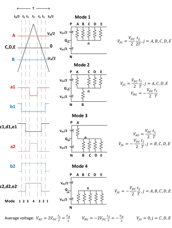
Irrespective of the control method used, the PWM signal generation can be achieved through conventional sine PWM (SPWM) or the space vector PWM (SVPWM). Additionally, analogous to the third harmonic injection PWM scheme used for three-phase inverters, a fifth harmonic injection PWM switching scheme can be used for five-phase inverters to reduce the peak voltage and improve the DC bus utilization. The different PWM methodologies, just as in the three-phase inverter, result in different levels of DC bus utilization [31]. The number of switching states in a five-phase motor is increased from 8 to 32, two of which are zero states. The 32 space vectors are arranged into 10 sectors as shown in Figure 5 with large, medium, and small vectors. When compared to the three-phase inverter, there are more degrees of freedom in choosing the switching
13
states for a given voltage reference. The strategy that is usually adopted to choose the right switching states is to ensure that the 3rd and 7th order harmonics are minimized. The maximum attainable output phase voltage using SVPWM scheme for a five-phase inverter is 5.15 % higher than obtainable using SPWM. The 4-vector SVPWM switching scheme that uses two medium and two large vectors results in the lowest amplitude of third harmonic at the expense of higher number switching transitions for a five-phase inverter [32]. (11100) (11000) (11001) (10001) (10011) (00011) (00111) (00110) (01110) (01100) (10000) (11101) (11010) (01001) (01000) (11110) (01101) (10100) (00100) (01010) (01111) (10110) (00010) (00101) (01011) (10111) (00001) (11011) (10010) (10101)
Figure 5. Switching states for SVPWM of a five-phase motor. Voltage vectors are of three different amplitudes
1.3.2 Fault-Tolerant Operation of Five-Phase Motors
With the gradual penetration of multiphase motor in critical applications like traction and aerospace, fault-tolerant operation of the five-phase motor has been extensively studied in the recent literature. The basic idea behind fault-tolerant operation is to apply current references in the x-y space to ensure that the fundamental component of the stator flux exists in the air gap even with four or three phases [33]. The applied x and y components can be selected based on different post fault operating criteria:
Minimum drive derating [33]
Minimum copper loss [34],[35]
Minimum torque ripple [36]
The control of the motor post fault is complicated by the fact that the motor is asymmetric after loss of a phase. The initial work on fault-tolerant control uses simple hysteresis current controllers [29] which operate with a variable switching frequency. The use of synchronous frame controllers is proposed in [37] but with additional complexity as compared to healthy operation. The reason for the added complexity is that, while the orthogonality of the d- and q-axes is maintained after loss of phase A, the decoupling between the d-q and x-y reference frames is lost. This introduces cross coupling terms in the voltage equations in the synchronous reference frames. In [38], model predictive control (MPC) has been adopted for post fault operation of a five-phase induction motor. By modifying the transformation matrix it has been shown that the model of the motor can be maintained the same before and after the fault making it possible to adopt the same MPC strategy. This control method however creates a heavy burden on the microcontroller
15
is the shift in the neutral voltage due to the back-EMF induced in the opened faulty phase [39]. This affects PWM-based switching methods, since the inverter leg voltage is no longer equal to the phase-to-neutral voltage of the motor and the neutral shift has to be indirectly compensated. In [39], a fault-tolerant control scheme that uses conventional synchronous frame controllers for the d-q current tracking and proportional resonant (PR) controllers for x-y current tracking has been used. The justification for this is based on the fact that the maximum-torque-post-fault-operation strategy requires that the fundamental components of stator currents are balanced. However due the asymmetry in the faulty motor, this would require unbalanced x- and y-axis current references in the stationary frame which then appear as oscillating components in the synchronous frame. The effective tracking of these oscillating x and y currents would depend on the bandwidth of the PI controller. On the other hand, tracking unbalanced currents is relatively easier with stationary frame PR controllers [40].
It is thus evident that, while several different strategies for calculating the post fault operating currents are available, the type of control adopted can be of varying complexity. The fact that the post fault system is inherently asymmetric adds additional sophistication to the control. With the availability of fast microcontrollers, it has become possible to implement some of the more advanced control methods involving predictive control and higher order controllers. By adopting proper discretization methods for digital implementation of these control methods, it can be shown that the post fault steady state
performance is mostly similar. The best control strategy for fast seamless transition should involve minimum change to the control loop when switching from healthy to fault-tolerant operating condition.
1.4 Fault-Tolerant Induction Motor Design
A few of the more commonly used approaches to make a motor inherently fault-tolerant are:
Electrical isolation between phase windings
Magnetic isolation between phase windings
Physical separation between phase windings
Electrical isolation from the converter side is achieved by using a modular topology with independent H-bridges for every phase [41] as shown in Figure 6. However this increases the cost and complexity of the drive and in only justified in highly sensitive applications like military and aerospace.
Magnetic and physical isolation between the phases can be achieved by adopting fractional slot concentrated winding (FSCW) configurations where each stator coil is wound around a single tooth as shown in Figure 7(a). FSCW configurations provide additional thermal and physical isolation between the phases when compared to distributed winding motors which have overlapping end connections as shown in Figure 7(b). For these motors, the number of slots per pole per phase is less than one making them suitable for high pole count designs. While complete isolation requires that the windings are single layered with only one coil side per slot, single layer windings affect the
17
performance of the motor. The stator MMF of a motor with single layered windings is rich in space harmonics creating high tooth and magnet lossses [5] . Tooth wound stators can also be found in switched-reluctance motors (SRMs) shown in Figure 8 which exhibit a very high level of fault tolerance due to very low magntic coupling between the phases and no magnets on the rotor. However, despite this advantage SRMs commonly suffer from low efficiency, noise and vibrations and are more complicated to control.
A B C
VDC
3 Phase Power Supply
Figure 6. Three-phase inverter using a modular motor drive topology with independent H-bridges for each phase
Figure 7. Comparison of stator windings (a) fractional slot concentrated winding and (b) a distributed winding [42]
Figure 8. Commercially available switchedreluctance motor (Source: Bulletin NAAC -009 US Motors Industrial SR Range Catalog)
FSCW configurations have been widely adopted for permanent magnet and specifically interior permanent magnet motors due to their ability to provide extremely torque dense designs. The copper utilization in an FSCW stator is much higher than a conventional distributed winding stator due to reduced overhang at the end connections. They also provide several additional advantages over conventional distributed windings such as higher fill factor and easier manufacturability [5]. In terms of inter-turn faults, while in an FSCW it is not possible to prevent the fault from spreading to more turns of the same phase coil due to the voltage induced in the faulted turns by the rotor magnets, they provide some means to contain the fault in the affected phase of the motor.
Due to these merits, there have been many recent but mostly unsuccessful attempts to apply FSCW to induction motors in the literature. The air gap flux density distribution created by using FSCW configurations is rich in sub and higher order space harmonics. Although this only translates to rotor and magnet losses in PM motors, in induction motors these harmonics induce currents in the cage rotor. This results in low average torque, high rotor copper loss as well as torque pulsations at different rotor speeds. In [42], the most commonly used FSCW slot-pole combinations for PM motors; the 1/2 slot per pole per
19
phase (SPP) and 2/5 SPP are used with induction motors with limited success. Although the double layered 1/2 SPP is shown to provide promising results it is not in par with a conventional integral SPP distributed winding in terms of average/ripple torque and rotor losses.
Multi-layer FSCW configurations have been used in PM motors to minimize losses by reducing or cancelling some of the sub and higher order space harmonics [43]. In [44], this idea is extended to induction motors while also using a multi-layer tooth wound rotor. Although this helped minimize some of the harmonics in the air gap flux and their interaction with the rotor, the resulting configurations still show to exhibit high torque pulsations. Additionally, the manufacturing advantage provided by using a rotor cage that can be die cast with aluminum or copper, is lost.
s R Lls 1 ms L rd1 L r R s 2 ms L 2 rd L 1 2(1 ) r R s msn L rdn L 1 (1 ) r R n s
Conventional design methods for induction motors use the simplified equivalent circuit model [45] that fails to capture these effects, which are negligible in distributed winding configurations, resulting in non-optimal designs. The effect of stator space harmonics on the steady state performance of induction motors can be analyzed by using the harmonic equivalent circuit shown in Figure 9. The torque speed curve obtained for a ½ SPP induction motor with 12 stator slots, 8 poles and a 44 bar rotor is shown in Figure 10. The Figure 10(a) also shows the average steady state torque due to each space harmonics. It is clear that the effect of the space harmonics degrades the performance of the motor. Adopting FSCW winding configurations for induction motors is a challenging problem.
Figure 10. Torque speed characteristics of a ½ SPP FSCW induction motor obtained from the harmonic equivalent circuit (a) average torque due to individual harmonics (b)
net average torque compared with results from Finite Element Analysis (FEA)
0 200 400 600 800 1000 1200 1400 1600 1800 -20 -10 0 10 20 30 40 Speed (rpm) Torque (Nm) 4-pole 8-pole(fund.) 16-pole 20-pole 44-pole 68-pole 0 200 400 600 800 1000 1200 1400 1600 1800 -20 -10 0 10 20 30 40 Speed (rpm) Torque (Nm)
Torque from Transient FEA
Torque from Harmonic Equivalent Circuit
21 1.5 Problem Statement
Based on the above literature, stator inter-turn faults have been identified as the most difficult to detect and the most destructive to the motor. While it may be not be possible to design an induction motor that is tolerant to inter-turn faults, adding redundancies in the form of additional phases seems to be a promising way to deal with the impacts of the fault for high reliability applications. Five-phase induction motors are an attractive option for high performance, safety critical and cost sensitive applications. Not only do they provide fault-tolerant capability but also improved performance as compared to equivalent three-phase motors. Widespread adoption of five-phase motors for practical applications has been limited due to the additional requirements in the inverter side and the relatively complicated control system. However, with the availability of low-cost high speed microcontrollers equipped with fast and high resolution ADCs, digital implementation of the control system is no longer an issue. Extensive work has been done with the fault-tolerant control of five-phase induction motors, but to benefit from the fault-tolerant capability, the motor drive system should include prognostics, detection, and isolation of the fault and finally fault-tolerant operation. Most of the methods used in the existing literature for fault diagnostics of stator windings rely on MCSA which, while shown to be effective requires additional hardware for data acquisition and spectral analysis. This is difficult to justify for five-phase motor drives in most applications considering the already added complexity in the drive with the addition of two phases. The aim of this dissertation is to integrate a low-cost non-intrusive inter-turn fault detection method with a fault-tolerant control scheme for five-phase induction
motors. Specifically the method should be easy to implement on the digital signal processor (DSP) or microcontroller that drives the motor.
The literature also suggests that there have been very few attempts to extend the benefits of FSCW configurations that provide better physical isolation between the stator phases to induction motors. The main issue has been the identified to be abundance of the lower order space harmonics in the air gap. While this only results in additional magnet losses in a PM rotor it significantly impacts the torque performance and increases the rotor losses with an induction rotor. Several modifications have been introduced to the stator windings of FSCW permanent magnet motors to minimize the magnet losses by eliminating the space harmonics using multilayer windings or adopting varying turns per slot. This direction seems promising because it requires no additional changes to the rotor or the motor control system. This dissertation also explores alternate methods for adopting FSCW configurations for induction motors.
1.6 Dissertation Outline
This dissertation has been organized into seven chapters. Chapter 2 covers control of five-phase induction motors before and after a fault, focusing on stationary frame controllers. The purpose for adoption of stationary frame control is to reduce the complexity of the control algorithm to allow for incorporation of an on board inter-turn fault diagnostic. Chapter 3 develops a detailed model of a multiphase induction motor with inter-turn fault. The purpose of the model is to understand the dynamics of the five-phase induction motor with an inter-turn fault in one of its phases and to test and validate the
23
fault detection method. Chapter 4 introduces a voltage injection based fault diagnostic method for detection of inter-turn fault. The fundamental basis of the method is developed and simulation results showing its effectiveness are presented. The drawbacks and possible complications with practical implementation and as well as methods to deal with these issues have been identified. Chapter 5 details a new multilayer FSCW configuration suitable for outer rotor induction motors. The proposed design eliminates the end winding overlap between the phases of the motor. Chapter 6 validates the proposed DC injection based diagnostic method through experimental results conducted on a 7.5 HP lab prototype motor with taps in the phases to create inter-turn faults. Chapter 7 presents the conclusions of this work.
2. CONTROLOFFIVE-PHASEINDUCTIONMOTORS
Five-phase motors provide several advantages over three-phase motors.
They can operate at reduced capacity with up to two of its five phases opened. For cost sensitive applications like electric submersible pumps (ESPs), this translates into reduced production but avoids exponential costs associated with downtimes and unscheduled maintenance.
For the same kVA and phase voltage rating, a five-phase motor requires lesser current per phase. This reduces the switching and conduction losses in the inverter switches, increasing their reliability.
With increase in the phase number, torque pulsation and acoustic noise problems are much less compared to conventional three-phase, current regulated induction motor drives.
The air gap flux harmonics of a five-phase motor are of higher order and smaller amplitude as compared to a three-phase motor. This results in lower harmonic currents in the rotor reducing the average rotor copper loss and improving the overall efficiency of the motor.
2.1 Control of Five-Phase Induction Motors Using Resonant Controllers
The first step to developing the control algorithm for a five-phase motor is the construction of a motor model. Just like a d-q transformation is used to remove the position dependence of the mutual inductance terms and decouple the flux equations, a similar
d-25
q-x-y transformation can be applied to a five-phase motor. For a five-phase motor the spatial distribution between the different phase windings is 72 degrees. The voltage and flux equations of a five-phase motor are given by (1)-(4)
𝑣𝑎𝑏𝑐𝑑𝑒𝑠 = 𝑅𝑠𝑖𝑎𝑏𝑐𝑑𝑒𝑠+ 𝑑𝜓𝑎𝑏𝑐𝑑𝑒𝑠 𝑑𝑡 (1) 𝑣𝑎𝑏𝑐𝑑𝑒𝑟 = 𝑅𝑟𝑖𝑎𝑏𝑐𝑑𝑒𝑟+𝑑𝜓𝑎𝑏𝑐𝑑𝑒𝑟 𝑑𝑡 (2) 𝜓𝑎𝑏𝑐𝑑𝑒𝑠 = 𝐿𝑠𝑠𝑖𝑎𝑏𝑐𝑑𝑒𝑠+ 𝐿𝑠𝑟𝑖𝑎𝑏𝑐𝑑𝑒𝑟 (3) 𝜓𝑎𝑏𝑐𝑑𝑒𝑠 = 𝐿𝑟𝑠𝑖𝑎𝑏𝑐𝑑𝑒𝑠+ 𝐿𝑟𝑟𝑖𝑎𝑏𝑐𝑑𝑒𝑟 (4) where,
𝑅𝑠 – Stator resistance matrix 𝑅𝑟 – Rotor resistance matrix
𝐿𝑠𝑠 – Stator self inductance matrix
𝐿𝑟𝑟 – Rotor self inductance matrix 𝐿𝑠𝑟, 𝐿𝑟𝑠 – Mutual inductance matrices
Similar to a conventional 3 phase motor the mutual inductance matrices are time dependent functions of rotor position. To simplify the above model a decoupling transformation of five orthogonal basis vectors (d-q-x-y-n) is defined by (5):
𝑇𝑠= √
2 5 [
cos(𝜃) cos(𝜃 − 𝛼) cos(𝜃 − 2𝛼) cos(𝜃 + 2𝛼) cos(𝜃 + 𝛼)
−sin(𝜃) −sin(𝜃 − 𝛼) −sin(𝜃 − 2𝛼) −sin(𝜃 + 2𝛼) −sin(𝜃 + 𝛼)
1 cos(2𝛼) cos(4𝛼) cos(4𝛼) cos(2𝛼)
0 sin(2𝛼) sin(4𝛼) −sin(4𝛼) −sin(2𝛼)
1 √2 1 √2 1 √2 1 √2 1 √2 ] (5)
where 𝛼=2𝜋5 and 𝜃 = 𝜔𝑡 is the instantaneous angular position of the d-axis with respect to the ‘a’ phase magnetic axis.
On applying the transformation, the voltage and flux equations of a five-phase motor reduce to (6)-(13) 𝑣𝑑𝑞𝑠 = 𝑅𝑠𝑖𝑑𝑞𝑠∓ 𝜔𝜓𝑞𝑑𝑠+ 𝑝𝜓𝑑𝑞𝑠 (6) 𝑣𝑑𝑞𝑟 = 𝑅𝑟𝑖𝑑𝑞𝑟∓ (𝜔 − 𝜔𝑟)𝜓𝑞𝑑𝑟+ 𝑝𝜓𝑑𝑞𝑟 (7) 𝑣𝑥𝑦𝑠 = 𝑅𝑠𝑖𝑥𝑦𝑠+ 𝑝𝜓𝑥𝑦𝑠 (8) 𝑣𝑥𝑦𝑟 = 𝑅𝑠𝑖𝑥𝑦𝑟+ 𝑝𝜓𝑥𝑦𝑟 (9) 𝜓𝑑𝑞𝑠 = 𝐿𝑠𝑖𝑑𝑞𝑠+ 𝐿𝑚𝑖𝑑𝑞𝑟, where 𝐿𝑠 = 𝐿𝑙𝑠+ 𝐿𝑚 (10) 𝜓𝑑𝑞𝑟 = 𝐿𝑟𝑖𝑑𝑞𝑟+ 𝐿𝑚𝑖𝑑𝑞𝑠, where 𝐿𝑟 = 𝐿𝑙𝑟+ 𝐿𝑚 (11) 𝜓𝑥𝑦𝑠 = 𝐿𝑙𝑠𝑖𝑥𝑦𝑠 (12) 𝜓𝑥𝑦𝑟 = 𝐿𝑙𝑟𝑖𝑥𝑦𝑟 (13)
Since the motor is star connected with no neutral wire, zero sequence components do not exist. From the above equations, it can be seen that the x-y space is completely decoupled from the d-q space and there exists no coupling between the stator and rotor flux in the x-y space. The five dimensional vector space is thus divided into 2 sub-spaces with the following characteristics:
d-q space - components that produce the air gap flux that links the rotor and are responsible for energy conversion
x-y space – components that do not produce a coupling flux and add only leakage fluxes and copper losses
27
Different space harmonics map into different subspaces as seen from Table 1. Table 1. Space harmonic mapping
COMPONENT HARMONICS
DQ 10j ±1 (j = 0,1,2,….)
XY 10j ±3 (j = 0,1,2,….)
N 10j ±5 (j = 0,1,2,….)
The torque production is only due to the d-q components and is given by (14)
𝑇𝑒 = 𝑃𝐿𝑚(𝑖𝑑𝑟𝑖𝑞𝑠− 𝑖𝑞𝑟𝑖𝑑𝑠) (14) The control of a five-phase motor can now be accomplished similar to a conventional three-phase motor where by orienting the rotor flux along the d-axis, it is possible to independently control the flux and torque using the d-axis and q-axis stator currents respectively. The transformation given in (5) is generalized for an arbitrary reference frame. The choice of the controller depends on the nature of the reference frame used to build the control loop and can be classified as follows:
Synchronous frame 𝜔 = 𝜔𝑒 – The frame rotates at synchronous speed which
corresponds to the fundamental operating frequency (𝜔𝑒) of the motor.
Stationary frame 𝜔 = 0 – The frame is fixed with the q-axis aligned with the magnetic ‘a’ phase axis.
In the synchronous frame all the variables like current, voltages and flux have constant DC values and so a conventional proportional integral (PI) controller can be used for current control to track a current reference. In the stationary frame, all the variables are sinusoidal functions at the fundamental frequency and a proportional resonant (PR)
controller can be used to track the current reference [46]. The transfer function of the PR controller is given by (15) 𝐶(𝑠) = 𝐾𝑝+ 𝐾𝑖 𝑠2 + 𝜔2 (15) where,
𝜔 = resonant frequency or the frequency of tracking signal
PR controllers are capable of achieving a zero steady state error at the selected resonant frequency. A PR controller is chosen for control for the following reasons:
Simpler reference frame transformation makes digital implementation easier. The only coupling term in the voltage equations (6) is the back-EMF voltage which
can be treated as a simple disturbance.
Enables on-line stator resistance estimation through DC injection. This is further discussed in Chapter 4.
Enables tracking of unbalanced current references which is required for fault-tolerant control.
Hence using a PR controller allows minimal change in the control loop between healthy and fault-tolerant operation. The overall current control loop with a PR controller is shown in Figure 11.
29
+
-+
* si
* si
2 2 e i p s K K ' 1 ' s s sL R )
(
e se
e
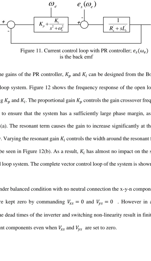
The gains of the PR controller, 𝐾𝑝 and 𝐾𝑖 can be designed from the Bode plot of
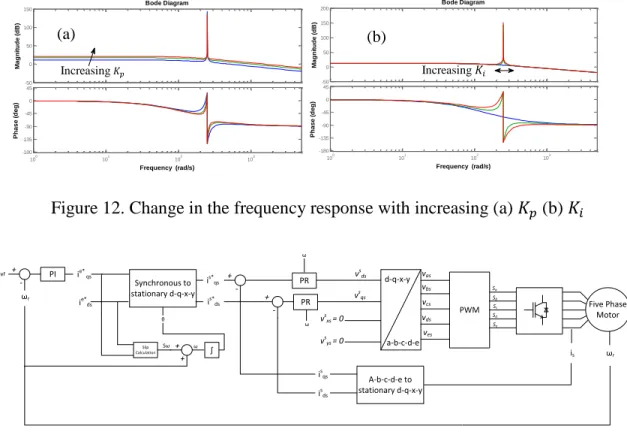
the open loop system. Figure 12 shows the frequency response of the open loop system for varying 𝐾𝑝 and 𝐾𝑖. The proportional gain 𝐾𝑝 controls the gain crossover frequency and is chosen to ensure that the system has a sufficiently large phase margin, as shown in Figure 12(a). The resonant term causes the gain to increase significantly at the resonant frequency. Varying the resonant gain 𝐾𝑖 controls the width around the resonant frequency. This can be seen in Figure 12(b). As a result, 𝐾𝑖 has almost no impact on the stability of the closed loop system. The complete vector control loop of the system is shown in Figure 13.
Under balanced condition with no neutral connection the x-y-n components of the current are kept zero by commanding 𝑉𝑥𝑠 = 0 and 𝑉𝑦𝑠 = 0 . However in a practical system, the dead times of the inverter and switching non-linearity result in finite x and y-axis current components even when 𝑉𝑥𝑠 and 𝑉𝑦𝑠 are set to zero.
Figure 11. Current control loop with PR controller; 𝑒𝑠(𝜔𝑒) is the back emf
Figure 13. Complete vector control loop of five-phase induction motor with PR controller
When using digital microcontrollers to control the motor the choice of discretization method affects the control performance. Based on [40], the zero-order hold based discretization method is used for practical implementation of the control loop. The discrete form of the resonant term of the PR controller is given by (16). The control loop shown in Figure 13 is simulated in MATLAB Simulink. A summary of the simulation results is shown in Figure 14. 𝑅(𝑧) = sin(𝜔0𝑇𝑠) 𝜔0 𝑧−1− 𝑧−2 1 − 2𝑧−1cos(𝜔 0𝑇𝑠) + 𝑧−2 (16) Five Phase Motor PWM d-q-x-y a-b-c-d-e vas vbs vcs vds ves vs ds vs xs = 0 PI ωref ωr + - i e* qs Sa Sb Sc Sd Se ωr ie* ds is A-b-c-d-e to stationary d-q-x-y is qs Synchronous to stationary d-q-x-y Slip Calculation + + Sω ω θ + -is* qs is ds + -is* ds PR PR ω ω vs qs vs ys = 0 ∫ -50 0 50 100 150 200 M a g n it u d e ( d B ) 100 101 102 103 -180 -135 -90 -45 0 45 P h a s e ( d e g ) Bode Diagram Frequency (rad/s) -50 0 50 100 150 M a g n it u d e ( d B ) 100 101 102 103 -180 -135 -90 -45 0 45 P h a s e ( d e g ) Bode Diagram Frequency (rad/s) Increasing𝐾𝑝 Increasing 𝐾𝑖 (a) (b)
31
2.2 Fault-Tolerant Control of Five-Phase Induction Motors
In general, fault tolerance is the ability of the motor to continue its operation in the event of a fault. For any multiphase motor with three or more phases, applying phase shifted currents to the phases creates a rotating magnetic field in the air gap of the motor, which is the primary requirement for torque production. For multiphase motors with more than three phases fault tolerance is possible due to the ability of the motor to operate after failure in one or more phases. In other words, the rotating magnetic field can still be created after loss of one or more phases.
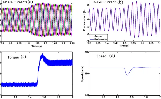
Figure 14. Simulation results of five-phase motor with PR controller with load change at t = 1.5s (a) Phase currents (b) d-axis current (c) torque (d) speed.
Specifically, five-phase motors can safely operate with loss of up to two phases without any additional hardware requirements. This is achieved by simply modifying the
1.35 1.4 1.45 1.5 1.55 1.6 1.65 1.7 1.75 -2 -1.5 -1 -0.5 0 0.5 1 1.5 2 Time (s) C u rr e n ts ( A ) 1 1.2 1.4 1.6 1.8 2 0 0.5 1 1.5 2 Time (s) T o rq u e ( N m ) 1 1.2 1.4 1.6 1.8 2 245 250 255 Time (s) S p e e d ( ra d /s ) Speed Torque Phase Currents 1.3 1.35 1.4 1.45 1.5 1.55 1.6 1.65 1.7 -3 -2 -1 0 1 2 3 Time (s) D a x is c u rr e n t (A ) Actual Reference D-Axis Current (a) (b) (c) (d)
control algorithm, which is generally implemented digitally on a microcontroller. While it is possible to operate three-phase motors with just two phases, this would require a neutral connection, a divided DC bus voltage, and applying a zero sequence component to the remaining healthy phases. Additionally, from a reliability standpoint, zero sequence currents have detrimental effect on the motor bearing and rapidly reduce the life of the motor. On the other hand zero sequence currents are not required for fault-tolerant operation of a five-phase motor.
It has been established in Section 2.1 that to create a sinusoidal air gap flux at fundamental frequency that links the rotor, a d-axis and a q-axis component of the current is required. The inverse transformation of currents from the d-q-x-y-n frame to the a-b-c-d-e frame is given by (17):
𝑖𝑎𝑏𝑐𝑑𝑒= √ 2 5 [ 1 0 1 0 1 √2 𝑐𝑜𝑠 (2𝜋 5) 𝑠𝑖𝑛 ( 2𝜋 5) 𝑐𝑜𝑠 ( 4𝜋 5 ) 𝑠𝑖𝑛 ( 4𝜋 5 ) 1 √2 𝑐𝑜𝑠 (4𝜋 5) 𝑠𝑖𝑛 ( 4𝜋 5) 𝑐𝑜𝑠 ( 8𝜋 5 ) 𝑠𝑖𝑛 ( 8𝜋 5 ) 1 √2 𝑐𝑜𝑠 (4𝜋 5) −𝑠𝑖𝑛 ( 4𝜋 5) 𝑐𝑜𝑠 ( 8𝜋 5 ) − 𝑠𝑖𝑛 ( 8𝜋 5) 1 √2 𝑐𝑜𝑠 (2𝜋 5) − 𝑠𝑖𝑛 ( 2𝜋 5) 𝑐𝑜𝑠 ( 4𝜋 5 ) − 𝑠𝑖𝑛 ( 4𝜋 5) 1 √2] 𝑖𝑑𝑞𝑥𝑦𝑛 (17)
Assuming that ‘a’ phase is opened, from the first row of the matrix in (17), it can be inferred that for 𝑖𝑎= 0 and no neutral connection (𝑖𝑛= 0),
𝑖𝑥 = −𝑖𝑑 (18)
Equation (18) implies that the d-q and x-y components are no longer independent and the x-axis current component is constrained by the system once the d-axis current is
33
fixed by the controller. On the other hand the y-axis current can be chosen based on the either for the following two conditions:
Phase currents in the remaining phases (b, c, d, and e) have the same amplitude – this ensures that the losses in the inverter switches are balanced and the drive derating is minimum. From (17) and (18) this condition results in (19)
𝑖𝑦 = −0.236𝑖𝑑 (19)
Total copper loss is minimum – this condition, given by (20)(19) , creates unequal phase currents, thereby reducing the reliability of the switches due to unbalanced loss distribution.
𝑖𝑦 = 0 (20)
The condition (19) is preferable and the phase shifts between the currents in the a-b-c-d-e frame under this condition are shown in Figure 15.
Figure 15. Phase shifts between the currents for fault-tolerant operation with one phase opened
In terms of the control loop, it may seem that the only modification from healthy operating condition is the addition of a current controller for the y-axis current. However since the phase A is left open it can be shown that the neutral voltage is no longer zero or
equal to the negative DC bus voltage [39]. For a drive-fed motor this would mean that the phase voltages of the motor cannot be controlled by modulating the corresponding leg voltages of the inverter. To compensate for this neutral shift the x-axis current has to be forced to be equal to the negative d-axis current. Thus a fault-tolerant operation can be achieved with one open phase. If any phase other than ‘a’ is opened, the transformation (5) can be rearranged such that the stationary q-axis is aligned with the magnetic axis of the opened phase. The control of d- and q-axis current components in the stationary reference frame remains unchanged since even after loss of phase ‘a’, the orthogonality and hence decoupling between the d and q axes is still retained. This is evident from the transformation matrix (5) after removing the first row and column and setting 𝜃 to be equal to zero.
When two phases ‘a’ and ‘b’ are opened, it is observed from (17) that once the d-axis and q-d-axis currents are fixed, constraints are imposed on both the x-d-axis and y-d-axis current components, given by (21), (22):
𝑖𝑥 = −𝑖𝑑 (21)
𝑖𝑦 = − 1.902𝑖𝑑− 1.618𝑖𝑞 (22)
The phase shifts between the currents in the a-b-c-d-e frame under the above conditions is shown in Figure 16. Similar to the single phase fault condition, for a drive-fed motor, the x-axis and y-axis currents have to be forced to track the above values, (21) and (22) to compensate for the shift in the neutral voltage and facilitate tracking of the d and q-axis reference currents.
35
Figure 16. Phase shifts between the currents for fault-tolerant operation with two phases opened
It is observed, form the above discussion, that for the same sinusoidal air gap flux, the amplitudes of the currents have to be increased above the rated value during faults and additionally, the resulting phase current amplitudes are unbalanced when there are two faulty phases. The modified control loop for fault-tolerant operation is shown in Figure 17. Five Phase Motor PWM d-q-x-y a-b-c-d-e vas vbs vcs vds ves vs ds PI ωref ωr + - i e* qs Sa Sb Sc Sd Se ωr ie* ds is A-b-c-d-e to stationary d-q-x-y is qs Synchronous to stationary d-q-x-y Slip Calculation + + Sω ω θ + -is* qs is ds + -is* ds PR PR v s qs ∫ is ys PR Fault Tolerant Control i s* ys + vsys -PR is xs -+ is* xs vsxs
Figure 17. Complete vector control loop of five-phase induction motor for fault-tolerant control
This method ensures minimal change to the controller enabling a seamless transition from healthy to fault-tolerant operation. In actual practice, in the absence of a “sinusoidal” winding distribution, non-zero x-y currents create harmonic flux in the air gap that result in some torque pulsations.
𝐼𝑚(𝑓𝑎𝑢𝑙𝑡) = 2.236𝐼𝑚(ℎ𝑒𝑎𝑙𝑡ℎ𝑦) for B,D 𝐼𝑚(𝑓𝑎𝑢𝑙𝑡) = 3.681𝐼𝑚(ℎ𝑒𝑎𝑙𝑡ℎ𝑦) for E
2.3 Chapter Summary
The control of five-phase induction motors in the stationary frame with resonant controllers is presented in this chapter. Implementation of the control loop in the stationary frame eliminates the need for a rotating frame transformation and also ensures that the modification to the control loop is minimal when transitioning to fault-tolerant operation. Irrespective of the post fault operating criteria it can be seen that two additional PR controlled current loops are required to ensure that a fundamental rotating magnetic field exists in the airgap after the loss of a phase. Another added advantage of implementing the control loop in the stationary frame is seen when performing a DC voltage injection for diagnostic purposes since the resonant controllers offer low gains outside of the resonant frequency. The method is discussed in detail in Chapter 4.
37
3. MODELINGOFINDUCTIONMOTORSWITHINTER-TURNFAULTS
A generalized model of the induction motor is developed to serve as a tool for fault analysis. The following factors are taken into account to develop the model
The effect of space harmonics due to slotting on the air gap flux
Adaptability to multiphase stator winding configurations
Accounting for skew in the rotor or stator
Adaptability to include inter-turn fault in the winding phases
3.1 Generalized Model of an Induction Motor
Based on the above requirements Modified Winding Function Theory (MWFT) is identified as a suitable method [47]. MWFT provides a simple method of calculating the self and mutual inductances of the motor from the winding functions of the phases. The winding function of a phase is defined as the MMF created in the air gap due to unit current flowing through the phase. The assumptions made when using winding function theory are:
Saturation in the core is negligible
The inter-bar current is negligible
Eddy current, friction and windage losses are neglected
𝐿𝑖𝑗 = 𝑙 ∫ 𝑀𝑖(𝜑) 2𝜋 0
𝑛𝑗(𝜑)𝑑𝑃(𝜑) (23)
where,
𝑀𝑖(𝜑) = Modified Winding Function of winding i 𝑛𝑗(𝜑) = Turns function of winding j
𝑃(𝜑) = Specific permeance
𝑙 = effective stack length
The modified winding function is given by,
𝑀𝑖(𝜑) = 𝑛𝑖(𝜑) − 1
2𝜋〈𝑃(𝜑)〉∫ 𝑛𝑖(𝜑) 2𝜋 0
𝑑𝑃(𝜑) (24)
To take into account the change in the reluctance due to the presence of slots on the stator and rotor, the specific permeance is modeled as a piecewise linear function along the air gap periphery for every rotor position. Some of the possible types of flux paths depending on the relative position of the stator and rotor slots are shown in Figure 18.
Stator
Rotor
t1 t2 t3 t4 t5 t6 t7 t8
39
The air gap is divided into sections formed by either of stator or rotor tooth edge and the mid points of the stator or rotor slots. Assuming that the flux lines trace a quarter circle before entering a tooth; a closed form expression for the specific permeance can be derived for each section. For example for the single sided fringing shown in Figure 19 (a) the expression for the specific permeance is given by (25). Similar expressions can be derived for all sections.
𝑃(𝜑) = ∫ 𝜇0 𝑔 +𝜋𝑥2 𝑏0
0
𝑑𝑥 (25)
Three different types of fringing are shown in Figure 19.
Single sided fringing
b0
g
Double sided fringing
Figure 19. Different types of flux fringing between the stator and rotor teeth
(a)
‘S’ shaped fringing
Figure 19. (Continued)
The rotor cage is modeled as individual loops as shown in Figure 20 with adjacent bars and the connecting end ring segments representing a phase. This makes it possible to apply the model to motors with non-integral bars per pole [47]. The specific permeance function is then used to calculate the self and mutual inductances between stator and rotor phases as a function of rotor position (or time for constant speed operation) for one complete mechanical revolution of the rotor.
Re Le Re Le Re Le Re Le Rb Lb Rb Lb Rb Lb ir(n-1) irn ir1 ir(n-2)
Figure 20. Rotor cage modeled as individual loops