NASeR el-SHeIMy, euN-HwAN SHIN, XIAojI NIu MobIle MultI-SeNSoR SySteMS ReSeARCH GRoup, DepARtMeNt of GeoMAtICS eNGINeeRING, tHe uNIveRSIty of CAlGARy, CANADA
t
oday, most vehicle navigation systems rely mainly on Global Positioning System (GPS) receivers as the primary source of information to provide the vehicle position for an unlimited number of users anywhere on the planet. Since its advent, the number of applications using GPS has increased dramatically and include tracking the location and speed of people, truck fleets, trains, ships, or planes; directing emergency vehicles to the scene of an accident; mapping where a city’s assets are located; and providing precise timing for endeavors that require large-scale co-ordination.GPS, however, can reliably provide
these types of information only under ideal conditions, that is, in open areas in which GPS satellite signals can be received. In other words, the sys-tem doesn’t work very well in urban canyons, canopy areas, and similar environments due to signal block-age and attenuation deteriorating the obtainable positioning accuracy. For the moment, any sophisticated urban application that demands essentially continuous position determination, cannot depend on GPS as a stand-alone system — those who have tried are still trying!
Cost and space constraints are currently driving manufacturers of vehicles to investigate and develop the next generation of low-cost and small-size navigation and guidance systems to meet the fast growing demand for in the location-based services and tele-matics markets. Advances in
micro-electro-mechanical systems (MEMS) technology have shed promising light on the development of such systems. But such sensors high noise and drift rate remain a problem, which may be alleviated in combination with GPS. Solutions that integrate navigation data have been recognized as the most challenging aspects that remain to turn MEMS-based inertial systems into robust, accurate navigation systems.
Introducing MeMS
The last two decades have shown an increasing demand for low-cost and miniature inertial sensors for many navigation applications. MEMS-based inertial sensors efficiently meet this demand. However, due to their light-weight and fabrication process, MEMS sensors still have some performance limitations, which consequently affect their obtainable accuracy and sensitivity.
Kalman
extended vs. unscented Kalman filters
filter
face-off
for Integrated GpS and MeMS Inertial
GpS and micro-electro-mechanical (MeMS) inertial systems have
complementary qualities that make integrated navigation systems more robust.
GpS maintains good accuracy but is subject to signal blockages; low-cost MeMS
are unaffected by satellite signal outages but their accuracy degrades rapidly over
time. Kalman filter techniques can help bring these two technologies together
synergistically. but which Kalman filtering design works best? A group of
Canadian researchers tackles the question.
C o p yr ig h t i St o ck .c o m /p ee te r v iis im aa
scale factor, and noise) are very large and sensitive to surrounding environ-mental changes. Therefore, navigation algorithms (i.e., estimators) should be able to deal with these uncertainties.
Traditionally the linearized man filter (LKF) or the extended Kal-man filter (EKF) have been used in the area of navigation, and recently the unscented Kalman filter (UKF) has been proposed for low-cost inertial navigation. The UKF approach offers several benefits. Because we do not need to develop a space navigator error model for a UKF, the system develop-ment time can be reduced. Moreover, because UKF is a second order filter, higher-order errors neglected by the EKF can be considered.
As discussed in the paper by Naser El-Sheimy and Eun-Hwan Shin (2004) cited in the Additional Resources sec-tion at the end of this article, a UKF can handle large attitude errors. Hence, we can use the UKF in navigation sys-tems based on crude inertial measure-ment units (IMUs)
In this article, we will compare the EKF with the UKF in terms of the state model equations and structure of the filters. Then we compare the performance of both filters by testing integrated GPS and MEMS-based IMU
two IMUs are currently available in the market, while the third one is a custom-built IMU developed by the Mobile Multi-Sensor Systems Research Group at the University of Calgary. The custom-built IMU integrates three accelerometers and three gyroscopes. In this article, we pay special atten-tion to the filters’ performance during the in-motion alignment and to the obtained positioning errors during GPS outages.
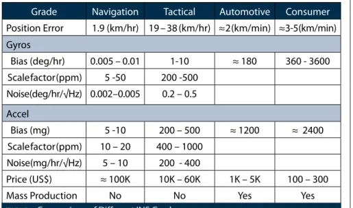
We begin by reviewing implemen-tation of the EKF and the UKF for the integration of low-cost INS (see table 1 for a comparison of the performance and cost of different INS grades) and GPS. Next, we will compare the per-formance of the two filters using three different MEMS-based IMUs and then draw conclusions from the test results.
A profile: the eKf
Traditionally, error state Kalman filters — either the LKF or the EKF — were used in the field of navigation. If an INS error control loop (feedback) exists, then the LKF can be considered as the EKF. A low-cost INS cannot operate for a long time without the feedback loop. Hence, this article will only discuss EKF implementation.
In developing the EKF, the system
system process model comprises the INS mechanization, a description of the evolution of the navigation param-eters (position, velocity and attitude), and the inertial sensor error models. Linearization of the system model can be done through perturbation analysis, a classical approach to INS error analy-sis. In the perturbation analysis, the navigation parameters are perturbed with respect to the true navigation frame (n-frame).
Alternatively, we can also analyze the INS error with respect to the com-puter frame (c-frame), the frame that the INS computer assumes to be the true navigation frame. The choice of an appropriate INS error model depends upon the given navigation scenario and is an important part of the navigation software design.
Regardless of the choice of the INS error model, the linearized system model can be described in discrete time as
(1) where is the error state vector at time ; is the state transition matrix, and is the driven response at due to the presence of the input white noise during the time interval. Because a white sequence is a sequence of a zero-mean random variable that is uncorrelated time-wise, the covariance matrix associated with wk is given as
(2) The linearized measurement equation can be written as follows:
(3) where is the measurement vector;
is a design matrix; and is the measurement noise vector. The mea-surement covariance matrix is written as
Grade Navigation tactical Automotive Consumer
position error 1.9 (km/hr) 19 – 38 (km/hr) ≈ 2 (km/min) ≈ 3-5 (km/min) Gyros bias (deg/hr) 0.005 – 0.01 1-10 ≈ 180 360 - 3600 Scale factor (ppm) 5 -50 200 -500 Noise (deg/hr/√Hz) 0.002 – 0.005 0.2 – 0.5 Accel bias (mg) 5 -10 200 – 500 ≈ 1200 ≈ 2400 Scale factor (ppm) 10 – 20 400 – 1000 Noise (mg /hr/√Hz) 5 – 10 200 - 400 price (uS$) ≈ 100K 10K – 60K 1K – 5K 100 – 300
Mass production No No yes yes
(4) The system noise and measurement noise are assumed to be uncorre-lated, i.e. for all i, k.
Another profile: the uKf
In the UKF, system noises are gener-ated and are passed through the system process model. So, the state vector, x, and the system noise vector, w, are aug-mented to create the augaug-mented state vector, xa:(5) The UKF is based on transforming a set of deterministically chosen points, called the sigma points, through the nonlinear system process and mea-surement models. The unscented trans-formation (UT) refers to the procedure of obtaining a set of the sigma points (SPs), , and the associated weights, , from the given mean, , and cova-riance, , satisfying
(6) where p is the number of sigma points. Of several proposals for the UT, the scaled spherical simplex UT was applied in this paper because it gener-ates minimal number of SPs. Scaling the sigma points is an important step in attitude estimation.
The UKF is a straightforward extension of the UT to the recursive estimation. First, we initialize the augmented states and covariance as follows:
(7)
where
and .
Then, the scaled simplex SPs are gener-ated. During the prediction stage, the SPs go through the nonlinear system process model
(8) where the superscript ‘+’ and ‘-’ denote the updated and predicted states, respectively; is the rotation rate of the body frame with respect to the inertial frame; and fb is the specific force measurement. (The article by Shin (2004) cited in the Additional Resources section describes the system process model m[·]well.) Then, the predicted mean and covariance are computed using the transformed sigma points as follows:
(9)
(10) where and are weights for the mean and covariance computation, respectively.
During the update state, the sigma points are transformed through the measurement model:
(11) The predicted measurement is com-puted as:
(12) Then, the rest of the update equations can be written as follows:
(13) (14) (15) (16) (17) (18) where zk and Rk are the measurement and its noise covariance, respectively; and Kk is the Kalman gain matrix.
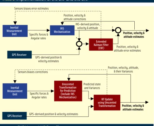
We summarize the implementa-tion steps of the EKF and UKF in table 2. Feedback of the biases can also be implemented to deal with the situation in which short-term correlated biases are superimposed on large long-term biases (See figure 1 for details on the data flow.)
tests and Results
This section compares the perfor-mance of the EKF and the UKF using datasets collected in land vehicles with three different MEMS-based IMUs. The same set of GPS receivers and postprocessing software were used in all of the tests. We use several IMUsKAlMAN fIlteR fACe-off
unscented Kalman filters have a number of clear advantages.
the mean and covariance of the state esti-mate is calculated to second order or better, as opposed to first order in the eKf. this leads to a more accurate implementation of the optimal recursive estimation equations, which is the basis for both the eKf and uKf
No explicit jacobian or Hessian calcula-tions are necessary for the uKf. this is especially valuable in situations where the system is a “black box” model in which the internal dynamic equations are unavailable.
built IMU sensor triads will be shown in detail as an example.
The first dataset used a prototype MEMS IMU manufactured through a in different field tests so as to be able
to draw general conclusions about the two estimation algorithms. In this article, only the results of the
custom-surface-micromachining process and well calibrated including cross-axis misalignment and thermal drift com-pensation. The test was conducted by Applanix Corporation in Toronto on March 5, 2003. The reference for the position, velocity and attitude are the smoothed best estimates (SBET) pro-vided by Applanix Corporation using postprocessing software and data from a tactical-grade IMU.
The attitude accuracy of the refer-ence solution is known to be 0.02° for roll and pitch, and 0.05° for head-ing, when there are no GPS outages. The vehicle used in the test was a van, which was driven with both low dynamics (small loops) and typical high-way condition (large rectangular loops). For most of the time, horizontal and vertical position accuracies of the DGPS solution were about 2–3 centi-meters and 4–9 centicenti-meters, respec-tively.
In the second dataset, the IMU used quartz tuning-fork gyroscopes. The field test was conducted in the propagation and covariance of the GRv, and when propagated through the true
nonlinear system, captures the posterior mean and covariance accurately to the 2nd order (taylor series expansion) for any nonlinearity.
Initialization 1. Initialize the error state and its covariance 1. Initialize the state and its covariance
2. Generate sigma points (Sps) for the initial states and covariance prediction 1.
2.
1. transform Sps through the INS mechanization
2. Compute mean and covariance from the transformed Sps 3. Generate sigma points for the predicted states and covariance update 1.
2.
3. 4.
1. transform Sps through the measurement model 2. Compute predicted measurement, ,
3. from the transformed Sps
4. Compute covariance between the state and the measurement, 5. Compute covariance of the innovation sequence, 6.
7. 8.
9. Generate sigma points for the updated states and covariance feedback position, velocity, attitude and bias bias
tAble 2. Implementation of the eKf and the uKf Sensors biases error estimates
Specific forces & Angular rates Inertial Measurement Unit Inertial Measurement Unit INS Mechanization Extended Kalman Filter (EKF) GPS Receiver GPS Receiver
GPS-derived position & velocity estimates Sensors biases corrections
Specific forces & Angular rates
GPS-derived position & velocity estimates Position, velocity & attitude corrections
INS-derived position, velocity & attitude
Position, velocity & attitude error estimates Position, velocity, attitude,
& their Variances Predicted state
and Variances
Position, velocity & attitude estimates
Position, velocity & attitude estimates + -+ -Unscented Transformation for Prediction (Include INS Mechanization) KF Update using Unscented Transformation
eters, we performed laboratory calibra-tions to obtain values for the biases, scale fac-tors, and cross-axis misalignments. As a result, the biases of the gyroscopes and accelerometers have been reduced to 0.5 deg/s and 6 mg, respectively.
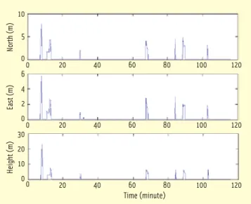
The third data-set was collected using the sen-sor triads mostly on a highway near the Calgary International Airport in a joint test with NovAtel, Inc. using a test van. A smoothed DGPS/INS solution from a navigation-grade IMU served as the reference. figures 3 and 4 show the tra-jectory and the accuracy of the DGPS solution, respectively. Although the sky was open for most of the time, build-ings and bridges resulted in frequent GPS outages and significant DGPS solution degradation.
All three datasets were processed by the EKF and the UKF using param-eters specifically tuned for each of the IMUs. Three processing scenarios for land vehicle navigations were consid-ered to compare these two algorithms.
KAlMAN fIlteR fACe-off
Research Park of the University of Calgary on March 4, 2003, operat-ing a passenger vehicle and driven with relatively low speed in a small area. Because no other higher grade IMU was used, we used the smoothed solution from the unscented Kalman smoother (UKS) as the reference for this dataset.
The prototype MEMS IMU devel-oped by the Mobile Multi-Sensor Sys-tems Research Group at the University of Calgary and is shown in figure 2. We refer to this IMU as the sensor tri-ads. Since the original bias errors of the triad’s sensors are as large as 20 deg/s for gyroscopes and 2 g for
accelerom-Scenario 1: Results with
Continuous GpS updates
The first scenario ran the algorithm with regular GPS updates. Our pur-pose was mainly to check whether the algorithms worked correctly or not. With continuous GPS measurements, the trajectory will generally follow that of the DGPS solution, while attitude errors will somehow reflect the quality of the integrated systems.The results from the three MEMS systems show that the attitude accura-cies can reach 0.1–0.4 degrees for pitch and roll, 0.7-1.3 degrees for heading. table 3 lists the performance of the sen-sor triads as an example. For all three datasets, the EKF and the UKF showed similar performance.
Scenario 2: Results with
Simulated GpS outages
In the second scenario we processed the datasets with simulated GPS out-ages, which covered typical drivingfIGuRe 2 the sensor triads developed by the Mobile Multi-Sensor Systems Research Group, the universityof Calgary (the dimension of the unit is 9.2x7.4x4.0 cm) 5000 4000 3000 2000 1000 0 North (m) -2000 -1000 0 1000 2000 3000 4000 5000 East (m) 10 5 0 North (m) 0 20 40 60 80 100 120 6 4 2 0 East (m) 0 20 40 60 80 100 120 30 20 10 0 Height (m) 0 20 40 60 80 100 120 Time (minute)
fIGuRe 3 trajectory of the third dataset fIGuRe 4 DGpS position accuracy of the third dataset
eKf uKf
position
(m) Northeast 0.081 0.0800.056 0.056 Height 0.169 0.149 Attitude
(deg) Rollpitch 0.230 0.2520.366 0.346 Heading 1.258 1.194
is a popular criterion for evaluating the performance of an integrated naviga-tion system. table 4 lists the maximum position errors during intentional 30-second GPS outages for the sensor triads. Again, the EKF and the UKF showed similar performance for each GPS outage in each direction. Gener-ally, the average position drift after 30 seconds of GPS signal outages were from 10 to 30 meters for the tested MEMS IMUs.
Scenario 3: Results with
large Initial Attitude errors
Typically, coarse alignment of an INS is done in stationary mode using level-ing (by accelerometers) followed by gyro-compassing or, alternatively by using an analytical method that solves the gravity and the Earth rotation measurements in one step. For MEMS-based IMUs, however, the gyroscopes are not accurate enough to sense the Earth’s rotation rate. Further, if the IMU is installed in a consumer vehicle, we cannot expect the user to wait until the alignment is finished. Hence, in-motion alignment is typically used.The GPS-derived velocity can be used for coarse in-motion alignment if the vehicle’s forward axis is parallel to the velocity vector. In airborne or
ship-borne applications, the vehicle may have lateral veloc-ity components. In such cases, the initial heading derived from the GPS velocity can have large errors. Initial tilt errors may also be large if the vehicle is in high-dynamic motion.
All these issues will cause large initial attitude errors, which was our third scenario.
Under these serious initial conditions, the assumption of linear error behavior for the EKF could be violated.
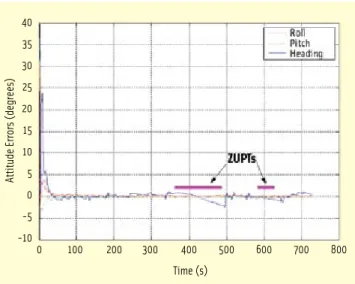
Because the EKF described in this article used a standard computer frame error model, the EKF could not deal with large attitude errors and generat-ed computational failure. On the other hand, the UKF converged as shown in figure 5. The convergence has been made within 50 seconds, and the RMS of attitude errors after the convergence is listed in table 5. For the EKF to cope with large attitude errors, a special INS error model must be developed. However, the UKF can deal with large attitude errors without devising a spe-cial model, and the transition from the large to small attitude errors is seam-less
Conclusions
This article has reviewed the imple-mentation of the EKF and the UKF and compared their performance for integrated low-cost inertial navigation systems. Both the EKF and the UKF work well for the integration of typical MEMS-based IMU and GPS. Perfor-mance of the EKF and the UKF is gen-erally similar (in both cases when GPS signals are available and when GPS signals are blocked).
The EKF requires a special naviga-tor error model to handle large initial attitude errors. However, the UKF can deal with such errors without addi-tional effort, and the transition from the large to small attitude uncertainties is seamless. Therefore, the UKF will be beneficial in the applications where in-motion alignment is required.
Acknowledgements
This study was funded by research grants from Natural Science and Engi-neering Research Council of Canada (NSERC) and Geomatics for Informed Decisions (GEOIDE), Network Centers of Excellence (NCE) awarded to Dr. Naser El-Sheimy. The authors would like to thank Dr. Bruno M. Scherzing-east (m) 46.653 47.066 Height (m) 0.983 0.708 2 North (m) 17.086 17.452 east (m) 11.873 11.802 Height (m) 2.628 2.014 3 North (m) 0.813 0.422 east (m) 28.424 29.180 Height (m) 3.574 3.736 4 North (m) 22.054 22.093 east (m) 5.200 5.002 Height (m) 0.946 0.829 5 North (m) 11.583 11.858 east (m) 1.402 0.773 Height (m) 1.373 1.468 6 North (m) 15.656 15.297 east (m) 15.020 14.708 Height (m) 0.531 0.731tAble 4. Maximum errors during 30s GpS outages (ADI Sensor triads)
time Roll pitch Heading
100–300 s 0.178 0.179 0.357 100–700 s 0.137 0.135 0.651
tAble 5. RMS of the attitude errors for large initial atitude uncertainties (degrees)
40 35 30 25 20 15 10 5 0 -5 -10
Attitude Errors (degrees)
0 100 200 300 400 500 600 700 800
Time (s)
fIGuRe 5 Attitude errors of the uKf under large initial attitude uncertainty (prototype IMu, first dataset).
er, Applanix Corporation, for provid-ing a dataset for the ISIS IMU test.
Manufacturers
OEM4 and MiLLennium from NovA-tel Inc., Calgary, Alberta, Canada, were used in the tests. The post-processed DGPS position solutions from GrafNav software from Waypoint Consult-ing, Inc., Calgary, were used as the measurement updates for the EKF and UKF in all datasets. The custom-built IMU integrates three accelerometers (ADXL105) and three gyroscopes (ADXRS150), both from Analog Devices Inc., Norwood, Massachusetts, USA. The first dataset used a prototype IMU (ISIS IMU) made by Inertial Sci-ence, Inc., Newbury Park, California, USA. The ISIS IMU used MEMS gyro-scopes from Analog Devices, Inc. The reference for the position, velocity and attitude are the smoothed best esti-mates (SBET) using POSPac software from Applanix Corporation (a Trim-ble company), Richmond Hill, Ontario, Canada. to process the data using a tactical-grade IMU the LN-200 from
Northrop Grumman, Navigation Systems Division, Woodland Hills, California. The second dataset used a MotionPak II IMU from BEI Systron Donner, Inertial Division, Concord, California. The third dataset was col-lected using the sensor triads and The smoothed DGPS/INS solution from a navigation-grade C-IMU, Honeywell Inc., Phoenix, Arizona, USA. All the three data were processed using AINS (Aided Inertial Navigation System (AINS™) software developed by by the Mobile Multi-Sensor Systems Research Group at the University of Calgary.
Additional Resources
beI technologies, Inc. (2002). Motionpak® II operating Manual. Systron Donner Inertial Divi-sion, beI technologies, Inc.benson jr., D. o. (1975). A Comparison of two Approaches to pure-Inertial and Dop-pler-Inertial error Analysis. Ieee transactions on Aerospace and electronic Systems, AeS-11(4):447–455
britting, K. R. (1971). Inertial Navigation Sys-tems Analysis. john wiley & Sons, Inc.
brown, R. G. and Hwang, p. y. C. (1992). Intro-duction to Random Signals and Applied Kalman filtering. john wiley & Sons, Inc., second edi-tion
el-Sheimy, N. and Niu, X. (2004). the Develop-ment of low-Cost MeMS-based IMu for land vehicle Navigation Applications. presentation in GeoIDe Annual Meeting, Gatineau, Qu´ebec, Canada (CD)
farrell, j. A. and barth, M. (1998). the Global positioning System & Inertial Navigation. McGraw–Hill
Hou, H. and el-Sheimy, N. (2003). Inertial Sensors errors Modeling using Allan variance. In proceedings of IoN GpS/GNSS, pages 2860– 2867, portland, oregon
julier, S. j. (2003). the Spherical Simplex unscented transformation. In proceedings of the Ieee American Control Conference, pages 2430–2434, Denver, Colorado
julier, S. j. and uhlmann, j. K. (1996). A General Method for Approximating Nonlinear transfor-mations of probability Distributions. technical report, Department of engineering Science, university of oxford, oxford, oX1 3pj, uK julier, S. j. and uhlmann, j. K. (2002). the Scaled unscented transformation. In proceed-ings of the Ieee American Control Conference, pages 4555–4559, Anchorage AK, uSA Rogers, R. M. (1997). IMu In-Motion Alignment without benefit of Attitude Initialization. Navi-gation: journal of the Institute of Navigation, 44(3):301–311
Scherzinger, b. M. (1996). Inertial Navigator error Models for large Heading uncertainty. In Ieee position location and Navigation Sympo-sium, pages 477–484
Scherzinger, b. M. and Reid, D. b. (1994). Modi-fied Strapdown Inertial Navigator error Models. In Ieee position location and Navigation Sym-posium, pages 426–430, las vegas, Nevada Schwarz, K.-p. and wei, M. (2000). INS/GpS Integration for Geodetic Applications: lecture Notes eNGo 623. Dept. of Geomatics eng., the university of Calgary, Calgary, Canada Shin, e.-H. (2001). Accuracy Improvement of low Cost INS/GpS for land Applications. uCGe Reports Number 20156, the university of Cal-gary, CalCal-gary, Alberta, Canada
Shin, e.-H. (2004). A Quaternion-based unscented Kalman filter for the Integration of GpS and MeMS INS. In proceedings of IoN GNSS, pages 1060–1068, long beach, California, uSA
Shin, e.-H. and el-Sheimy, N. (2004). An unscented Kalman filter for In-Motion Align-ment of low-Cost IMus. In proceedings of Ieee position, location, and Navigation Symposium, pages 273–279, Monterey, CA.
wan, e. A. and van der Merwe, R. (2001). Kal-man filtering and Neural Networks, Haykin, S. (ed.), chapter 7. john wiley & Sons, New york
Authors
Naser el-Sheimy is a professor and the leader of the Mobile Multi-sensor Research Group at the university of Calgary, Canada. He holds a Canada Research Chair (CRC) in Mobile Multi-Sensors Geomatics Systems. el-Sheimy¹s area of exper-tise is in the integration of GpS/INS/imaging sensors for mapping and GIS applications with special emphasis on the use ofmulti-sensors in mobile mapping systems. He acheived a b.Sc. (Honor) degree in civil engineering and an M.Sc. Degree in surveying engineering from Ain Shams university, egypt, and a ph.D. in geomat-ics engineering from the university of Calgary, Alberta, Canada. Currently, el-Sheimy is the chair of the International Society for photo-grammetry and Remote Sensing working Group on “Integrated Mobile Mapping Systems,” the vice-chair of the special study group for mobile multi-sensor systems of the International Association of Geodesy and the chairman of the International federation of Surveyors (fIG) working group C5.3 on Integrated positioning, Navigation and Mapping Systems. eun-Hwan Shin is currently a navigation analyst for Applanix Corportion, in toronto, Canada. He obtained his ph.D. from the Department of Geomatics engineering at the university of Calgary. He holds a b.Sc. and an M.Sc. from the Seoul National university in Korea and an M.Sc. in geomatics engineering from the university of Calgary. Shin has developed a Matlab INS toolbox during his ph.D. program at u of C. His research interest is on developing estimation methods for low-cost inertial navigation sys-tems.
Xiaoji Niu is a post doctoral fellow and a member of the mobile multi-sensor research group in the Department of Geomatics engineering at the university of Calgary. He has a ph.D. in the Department of precision Instruments & Mecha-nology at tsinghua university. Niu received the b.S. degrees (with honors) in both mechanical engineering and electrical engineering from tsinghua university in 1997. His research inter-est focuses on the low-cost GpS/INS integra-tion technologies and micromachined (that is, MeMS) inertial sensors and systems.