SIM900_AT Command
Manual_ V1.03
Document Title: SIM900 AT Command Manual
Version: 1.03
Date: 2010-12-24
Status: Release
Document Control ID: SIM900_AT Command Manual_V1.03
General Notes
SIMCom offers this information as a service to its customers, to support application and engineering efforts that use the products designed by SIMCom. The information provided is based upon requirements specifically provided to SIMCom by the customers. SIMCom has not undertaken any independent search for additional relevant information, including any information that may be in the customer’s possession. Furthermore, system validation of this product designed by SIMCom within a larger electronic system remains the responsibility of the customer or the customer’s system integrator. All specifications supplied herein are subject to change.
Copyright
This document contains proprietary technical information which is the property of Shanghai SIMCom Wireless Solutions Ltd, copying of this document and giving it to others and the using or communication of the contents thereof, are forbidden without express authority. Offenders are liable to the payment of damages. All rights reserved in the event of grant of a patent or the registration of a utility model or design. All specification supplied herein are subject to change without notice at any time.
Version History
Version Chapter What is new
V1.00 New version Created on the basis of SIM900 AT Test Result V1.01 3.2.50 AT+CALS 6.2.27 AT+CBTE 6.2.30 AT+STTONE 8.2.21 AT+CIPDPDP 8.2.25AT+CIPUDPMODE 6.2.45 AT+SGPIO 6.2.46 AT+SPWM 6.2.47 AT+ECHO
Add new command Add new command Add new command Add new command Add new command Add new command Add new command Add new command V1.02 3.2.16 AT+CLCC
3.2.30 AT+CR
Add write command Add parameter GPRS V1.03 6.2.47 AT+SPWM 6.2.48 AT+ECHO 6.2.50 AT+GSMBUSY 8.2.26 AT+CIPRXGET 8.2.27 AT+CIPQRCLOSE 8.2.28 AT+CIPSCONT 9.2.1 AT+SAPBR 10.2.x HTTP commands 11.2.x FTP commands
Modified the command Modified the parameter scope Add new command
Add new command Add new command Add new command Add new command Add new commands Add new commands
Contents
1 Introduction...11
1.1 Scope of the document ...11
1.2 Related documents ...11
1.3 Conventions and abbreviations ...12
1.4 AT Command syntax ...12
1.4.1 Basic syntax ...12
1.4.2 S Parameter syntax...13
1.4.3 Extended Syntax...13
1.4.4 Combining AT commands on the same Command line...13
1.4.5 Entering successive AT commands on separate lines...13
1.5 Supported character sets...13
1.6 Flow control ...14
1.6.1 Software flow control (XON/XOFF flow control)...14
1.6.2 Hardware flow control (RTS/CTS flow control)...15
2 AT Commands According to V.25TER...16
2.1 Overview of AT Commands According to V.25TER ...16
2.2 Detailed Description of AT Commands According to V.25TER ...17
2.2.1 A/ Re-issues the Last Command Given...17
2.2.2 ATA ANSWER AN INCOMING CALL ...17
2.2.3 ATD Mobile Originated Call to Dial A Number...18
2.2.4 ATD><n> Originate Call to Phone Number in Current Memory...20
2.2.5 ATD><str> Originate Call to Phone Number in Memory Which Corresponds to Field <str> ...21
2.2.6 ATDL Redial Last Telephone Number Used...23
2.2.7 ATE Set Command Echo Mode ...23
2.2.8 ATH Disconnect Existing Connection...24
2.2.9 ATI Display Product Identification Information ...25
2.2.10 ATL Set Monitor speaker loudness...25
2.2.11 ATM Set Monitor Speaker Mode ...25
2.2.12 +++ Switch from Data Mode or PPP Online Mode to Command Mode ...25
2.2.13 ATO Switch from Command Mode to Data Mode...26
2.2.14 ATP Select Pulse Dialling...26
2.2.15 ATQ Set Result Code Presentation Mode...26
2.2.16 ATS0 Set Number of Rings before Automatically Answering the Call...27
2.2.17 ATS3 Set Command Line Termination Character ...27
2.2.18 ATS4 Set Response Formatting Character ...28
2.2.19 ATS5 Set Command Line Editing Character...28
2.2.20 ATS6 Pause Before Blind Dialling...29
2.2.21 ATS7 Set Number of Seconds to Wait for Connection Completion...29
2.2.22 ATS8 Set Number of Seconds to Wait for Comma Dial Modifier Encountered in Dial String of D Command ...30
2.2.24 ATT Select Tone Dialing ...31
2.2.25 ATV TA Response Format ...31
2.2.26 ATX Set CONNECT Result Code Format and Monitor Call Progress ...32
2.2.27 ATZ Reset Default Configuration ...32
2.2.28 AT&C Set DCD Function Mode ...33
2.2.29 AT&D Set DTR Function Mode...34
2.2.30 AT&F Factory Defined Configuration ...34
2.2.31 AT&V Display Current Configuration ...36
2.2.32 AT&W Store Active Profile ...36
2.2.33 AT+GCAP Request Complete TA Capabilities List ...37
2.2.34 AT+GMI Request Manufacturer Identification ...37
2.2.35 AT+GMM Request TA Model Identification ...38
2.2.36 AT+GMR Request TA Revision Identification of Software Release...38
2.2.37 AT+GOI Request Global Object Identification ...38
2.2.38 AT+GSN Request TA Serial Number Identification (IMEI) ...39
2.2.39 AT+ICF Set TE-TA Control Character Framing...39
2.2.40 AT+IFC Set TE-TA Local Data Flow Control ...40
2.2.41 AT+IPR Set TE-TA Fixed Local Rate ...41
2.2.42 AT+HVOIC Disconnect Voice Call Only...42
3 AT Commands According to GSM07.07...43
3.1 Overview of AT Command According to GSM07.07 ...43
3.2 Detailed Descriptions of AT Command According to GSM07.07 ...44
3.2.1 AT+CACM Accumulated Call Meter (ACM) Reset or Query...44
3.2.2 AT+CAMM Accumulated Call Meter Maximum (ACM max) Set or Query ...45
3.2.3 AT+CAOC Advice of Charge ...46
3.2.4 AT+CBST Select Bearer Service Type...47
3.2.5 AT+CCFC Call Forwarding Number and Conditions Control ...48
3.2.6 AT+CCWA Call Waiting Control ...49
3.2.7AT+CEER Extended Error Report ...51
3.2.8 AT+CGMI Request Manufacturer Identification ...53
3.2.9 AT+CGMM Request Model Identification...53
3.2.10 AT+CGMR Request TA Revision Identification of Software Release...54
3.2.11 AT+CGSN Request Product Serial Number Identification (Identical with +GSN)...54
3.2.12 AT+CSCS Select TE Character Set...55
3.2.13 AT+CSTA Select Type of Address ...56
3.2.14 AT+CHLD Call Hold and Multiparty...56
3.2.15 AT+CIMI Request International Mobile Subscriber Identity...57
3.2.16 AT+CLCC List Current Calls of ME...58
3.2.17 AT+CLCK Facility Lock...60
3.2.18 AT+CLIP Calling Line Identification Presentation ...61
3.2.19 AT+CLIR Calling Line Identification Restriction...62
3.2.20 AT+CMEE Report Mobile Equipment Error...63
3.2.21 AT+COLP Connected Line Identification Presentation ...64
3.2.23 AT+CPAS Phone Activity Status...67
3.2.24 AT+CPBF Find Phonebook Entries...67
3.2.25 AT+CPBR Read Current Phonebook Entries ...69
3.2.26 AT+CPBS Select Phonebook Memory Storage...69
3.2.27 AT+CPBW Write Phonebook Entry...71
3.2.28 AT+CPIN Enter PIN...72
3.2.29 AT+CPWD Change Password...73
3.2.30 AT+CR Service Reporting Control ...74
3.2.31 AT+CRC Set Cellular Result Codes for Incoming Call Indication ...74
3.2.32 AT+CREG Network Registration...75
3.2.33 AT+CRLP Select Radio Link Protocol Parameters ...77
3.2.34 AT+CRSM Restricted SIM Access ...77
3.2.35 AT+CSQ Signal Quality Report ...78
3.2.36 AT+FCLASS FAX: Select, Read or Test Service Class ...79
3.2.37 AT+FMI FAX: Report Manufactured ID...80
3.2.38 AT+FMM FAX: Report Model ID ...80
3.2.39 AT+FMR FAX: Report Revision ID ...80
3.2.40 AT+VTD Tone Duration...81
3.2.41 AT+VTS DTMF and Tone Generation...81
3.2.42 AT+CMUX Multiplexer Control...82
3.2.43 AT+CNUM Subscriber Number...84
3.2.44 AT+CPOL Preferred Operator List...85
3.2.45 AT+COPN Read Operator Names...85
3.2.46 AT+CFUN Set Phone Functionality...86
3.2.47 AT+CCLK Clock...87
3.2.48 AT+CSIM Generic SIM Access ...87
3.2.49 AT+CALM Alert Sound Mode...88
3.2.50 AT+CALS Alert Sound Select...89
3.2.51 AT+CRSL Ringer Sound Level...89
3.2.52 AT+CLVL Loud Speaker Volume Level ...90
3.2.53 AT+CMUT Mute Control...91
3.2.54 AT+CPUC Price Per Unit and Currency Table...92
3.2.55 AT+CCWE Call Meter Maximum Event ...92
3.2.56 AT+CBC Battery Charge...93
3.2.57 AT+CUSD Unstructured Supplementary Service Data...94
3.2.58 AT+CSSN Supplementary Services Notification ...95
4 AT Commands According to GSM07.05...97
4.1 Overview of AT Commands According to GSM07.05...97
4.2 Detailed Descriptions of AT Commands According to GSM07.05...97
4.2.1 AT+CMGD Delete SMS Message...97
4.2.2 AT+CMGF Select SMS Message Format ...98
4.2.3 AT+CMGL List SMS Messages from Preferred Store...99
4.2.4 AT+CMGR Read SMS Message...102
4.2.6 AT+CMGW Write SMS Message to Memory ...106
4.2.7 AT+CMSS Send SMS Message from Storage ...108
4.2.8 AT+CNMI New SMS Message Indications ...108
4.2.9 AT+CPMS Preferred SMS Message Storage ... 111
4.2.10 AT+CRES Restore SMS Settings... 111
4.2.11 AT+CSAS Save SMS Settings ...112
4.2.12 AT+CSCA SMS Service Center Address ...113
4.2.13 AT+CSCB Select Cell Broadcast SMS Messages...114
4.2.14 AT+CSDH Show SMS Text Mode Parameters ...115
4.2.15 AT+CSMP Set SMS Text Mode Parameters ...115
4.2.16 AT+CSMS Select Message Service...116
5 AT Commands for SIM Application Toolkit...118
5.1 STK AT Command...118
6 AT Commands Special for SIMCOM...120
6.1 Overview...120
6.2 Detailed Descriptions of Commands...121
6.2.1 AT+SIDET Change the Side Tone Gain Level...121
6.2.2 AT+CPOWD Power Off ...122
6.2.3 AT+SPIC Times Remained to Input SIM PIN/PUK...122
6.2.4 AT+CMIC Change the Microphone Gain Level...123
6.2.5 AT+CALA Set Alarm Time...124
6.2.6 AT+CALD Delete Alarm...125
6.2.7 AT+CADC Read ADC ...125
6.2.8 AT+CSNS Single Numbering Scheme ...125
6.2.9 AT+CDSCB Reset Cell Broadcast...126
6.2.10 AT+CMOD Configure Alternating Mode Calls ...126
6.2.11 AT+CFGRI Indicate RI When Using URC ...127
6.2.12 AT+CLTS Get Local Timestamp...127
6.2.13 AT+CEXTHS External Headset Jack Control ...129
6.2.14 AT+CEXTBUT Headset Button Status Reporting ...130
6.2.15 AT+CSMINS SIM Inserted Status Reporting...131
6.2.16 AT+CLDTMF Local DTMF Tone Generation ...131
6.2.17 AT+CDRIND CS Voice/Data Call Termination Indication ...132
6.2.18 AT+CSPN Get Service Provider Name from SIM ...133
6.2.19 AT+CCVM Get and Set the Voice Mail Number on the SIM ...133
6.2.20 AT+CBAND Get and Set Mobile Operation Band ...134
6.2.21 AT+CHF Configure Hands Free Operation...135
6.2.22 AT+CHFA Swap the Audio Channels ...135
6.2.23 AT+CSCLK Configure Slow Clock ...136
6.2.24 AT+CENG Switch On or Off Engineering Mode ...137
6.2.25 AT+SCLASS0 Store Class 0 SMS to SIM When Received Class 0 SMS ...139
6.2.26 AT+CCID Show ICCID ...139
6.2.27 AT+CMTE Set Critical Temperature Operating Mode or Query Temperature...139
6.2.29 AT+CSDT Switch On or Off Detecting SIM Card...140
6.2.30 AT+CMGDA Delete All SMS...141
6.2.31 AT+STTONE Play SIM Toolkit Tone...142
6.2.32 AT+SIMTONE Generate Specifically Tone...143
6.2.33 AT+CCPD Enable or Disable Alpha String...143
6.2.34 AT+CGID Get SIM Card Group Identifier...144
6.2.35 AT+MORING Show State of Mobile Originated Call...144
6.2.36 AT+CMGHEX Enable or Disable Sending Non-ASCII Character SMS ...145
6.2.37AT+AUTEST Audio Channel Loopback Test...146
6.2.38AT+CCODE Configure SMS Code Mode...146
6.2.39 AT+CIURC Enable or Disable Initial URC Presentation ...147
6.2.40 AT+CPSPWD Change PS Super Password ...147
6.2.41 AT+EXUNSOL Enable or Disable Proprietary Unsolicited Indications...148
6.2.42 AT+CGMSCLASS Change GPRS Multislot Class ...148
6.2.43 AT+CDEVICE View Current Flash Device Type ...149
6.2.44 AT+CCALR Call Ready Query ...149
6.2.45 AT+GSV Display Product Identification Information...150
6.2.46 AT+SGPIO Control the GPIO...150
6.2.47 AT+SPWM Generate the Pulse-Width-Modulation ...151
6.2.48 AT+ECHO Echo Cancellation Control ...152
6.2.49 AT+CAAS Control Auto Audio Switch ...153
6.2.50 AT+SVR Configure Voice Coding Type for Voice Calls...154
6.2.51 AT+GSMBUSY Reject Incoming Call...155
7 AT Commands for GPRS Support...156
7.1 Overview of AT Commands for GPRS Support...156
7.2 Detailed Descriptions of AT Commands for GPRS Support...156
7.2.1 AT+CGATT Attach or Detach from GPRS Service ...156
7.2.2 AT+CGDCONT Define PDP Context ...157
7.2.3 AT+CGQMIN Quality of Service Profile (Minimum Acceptable) ...159
7.2.4 AT+CGQREQ Quality of Service Profile (Requested) ...160
7.2.5 AT+CGACT PDP Context Activate or Deactivate ...162
7.2.6 AT+CGDATA Enter Data State ...162
7.2.7 AT+CGPADDR Show PDP Address ...163
7.2.8 AT+CGCLASS GPRS Mobile Station Class...164
7.2.9 AT+CGEREP Control Unsolicited GPRS Event Reporting...165
7.2.10 AT+CGREG Network Registration Status ...166
7.2.11 AT+CGSMS Select Service for MO SMS Messages ...167
8 AT Commands for TCPIP Application Toolkit ...169
8.1 Overview...169
8.2 Detailed Descriptions of Commands...170
8.2.1 AT+CIPMUX Start Up Multi-IP Connection ...170
8.2.2 AT+CIPSTART Start Up TCP or UDP Connection...170
8.2.3 AT+CIPSEND Send Data Through TCP or UDP Connection...172
8.2.5 AT+CIPACK Query Previous Connection Data Transmitting State...175
8.2.6 AT+CIPCLOSE Close TCP or UDP Connection ...176
8.2.7 AT+CIPSHUT Deactivate GPRS PDP Context ...176
8.2.8 AT+CLPORT Set Local Port ...177
8.2.9 AT+CSTT Start Task and Set APN, USER NAME, PASSWORD...177
8.2.10 AT+CIICR Bring Up Wireless Connection with GPRS or CSD ...178
8.2.11 AT+CIFSR Get Local IP Address...179
8.2.12 AT+CIPSTATUS Query Current Connection Status ...179
8.2.13 AT+CDNSCFG Configure Domain Name Server...181
8.2.14 AT+CDNSGIP Query the IP Address of Given Domain Name...181
8.2.15 AT+CIPHEAD Add an IP Head at the Beginning of a Package Received...182
8.2.16 AT+CIPATS Set Auto Sending Timer ...183
8.2.17 AT+CIPSPRT Set Prompt of ‘>’ When Module Sends Data...183
8.2.18 AT+CIPSERVER Configure Module as Server ...184
8.2.19 AT+CIPCSGP Set CSD or GPRS for Connection Mode ...185
8.2.20 AT+CIPSRIP Show Remote IP Address and Port When Received Data ...186
8.2.21 AT+CIPDPDP Set Whether to Check State of GPRS Network Timing ...187
8.2.22 AT+CIPMODE Select TCPIP Application Mode...188
8.2.23AT+CIPCCFG Configure Transparent Transfer Mode ...188
8.2.24 AT+CIPSHOWTP Display Transfer Protocol in IP Head When Received Data...189
8.2.25 AT+CIPUDPMODE UDP Extended Mode...190
8.2.26 AT+CIPRXGET Get Data from Network Manually ...191
8.2.27 AT+CIPQRCLOSE Quick Remote Close ...192
8.2.28 AT+CIPSCONT Save TCPIP Application Context ...192
9 AT Commands for IP Application ...194
9.1 Overview...194
9.2 Detailed Descriptions of Commands...194
9.2.1 AT+SAPBR Bearer Settings for Applications Based on IP...194
10 AT Commands for HTTP Application...196
10.1 Overview...196
10.2 Detailed Descriptions of Commands...196
10.2.1 AT+HTTPINIT Initialize HTTP Service ...196
10.2.2 AT+HTTPTERM Terminate HTTP Service...196
10.2.3 AT+HTTPPARA Set HTTP Parameters Value ...197
10.2.4 AT+HTTPDATA Input HTTP Data ...198
10.2.5 AT+HTTPACTION HTTP Method Action ...199
10.2.6 AT+HTTPREAD Read the HTTP Server Response...201
10.2.7 AT+HTTPSCONT Save HTTP Application Context ...202
11 AT Commands for FTP Application...203
11.1 Overview ...203
11.2 Detailed Descriptions of Commands...203
11.2.1 AT+FTPPORT Set FTP Control Port...203
11.2.2 AT+FTPMODE Set Active or Passive FTP Mode...204
11.2.4 AT+FTPPUTOPT Set FTP Put Type ...205
11.2.5 AT+FTPCID Set FTP Bearer Profile Identifier ...206
11.2.6 AT+FTPREST Set Resume Broken Download ...206
11.2.7 AT+FTPSERV Set FTP Server Address ...207
11.2.8 AT+FTPUN Set FTP User Name ...208
11.2.9 AT+FTPPW Set FTP Password ...208
11.2.10 AT+FTPGETNAME Set Download File Name ...209
11.2.11 AT+FTPGETPATH Set Download File Path ...209
11.2.12 AT+FTPPUTNAME Set Upload File Name ...210
11.2.13 AT+FTPPUTPATH Set Upload File Path...211
11.2.14 AT+FTPGET Download File...211
11.2.15 AT+FTPPUT Set Upload File...212
11.2.16 AT+FTPSCONT Save FTP Application Context ...213
12 Supported Unsolicited Result Codes...215
12.1 Summary of CME ERROR Codes...215
12.2 Summary of CMS ERROR Codes ...216
13 AT Commands Sample ...219
13.1 Profile Commands...219
13.2 SIM Commands ...220
13.3 General Commands...221
13.4 Call Control Commands...222
13.5 SIM Toolkit Commands ...224
13.6 Audio Commands...224
13.7 SMS Commands ...224
1 Introduction
1.1 Scope of the document
This document presents the AT Command Set for SIMCOM SIM900 series cellular engine.
1.2 Related documents
You can visit the SIMCom Website using the following link: http://www.sim.com
1.3 Conventions and abbreviations
In this document, the GSM engines are referred to as following term: 1) ME (Mobile Equipment);
2) MS (Mobile Station); 3) TA (Terminal Adapter);
4) DCE (Data Communication Equipment) or facsimile DCE (FAX modem, FAX board); In application, controlling device controls the GSM engine by sending AT Command via its serial interface. The controlling device at the other end of the serial line is referred to as following term: 1) TE (Terminal Equipment);
2) DTE (Data Terminal Equipment) or plainly "the application" which is running on an embedded system;
1.4 AT Command syntax
The "AT" or "at" prefix must be set at the beginning of each Command line. To terminate a Command line enter <CR>.
Commands are usually followed by a response that includes. "<CR><LF><response><CR><LF>" Throughout this document, only the responses are presented, <CR><LF> are omitted intentionally.
The AT Command set implemented by SIM900 is a combination of GSM07.05, GSM07.07 and ITU-T recommendation V.25ter and the AT commands developed by SIMCom.
Note: A HEX string such as "00 49 49 49 49 FF FF FF FF" will be sent out through serial port at the baud rate of 115200 immediately after SIM900 is powered on. The string shall be ignored since it is used for synchronization with PC tool. Only enter AT Command through serial port after SIM900 is powered on and Unsolicited Result Code "RDY" is received from serial port. If auto-bauding is enabled, the Unsolicited Result Codes "RDY" and so on are not indicated when you start up the ME, and the "AT" prefix, not "at" prefix must be set at the beginning of each command line.
All these AT commands can be split into three categories syntactically: "basic", "S parameter", and "extended". These are as follows:
1.4.1 Basic syntax
These AT commands have the format of "AT<x><n>", or "AT&<x><n>", where "<x>"is the Command, and "<n>"is/are the argument(s) for that Command. An example of this is "ATE<n>", which tells the DCE whether received characters should be echoed back to the DTE according to the value of "<n>". "<n>" is optional and a default will be used if missing.
1.4.2 S Parameter syntax
These AT commands have the format of "ATS<n>=<m>", where "<n>" is the index of the S register to set, and "<m>"is the value to assign to it. "<m>" is optional; if it is missing, then a default value is assigned.
1.4.3 Extended Syntax
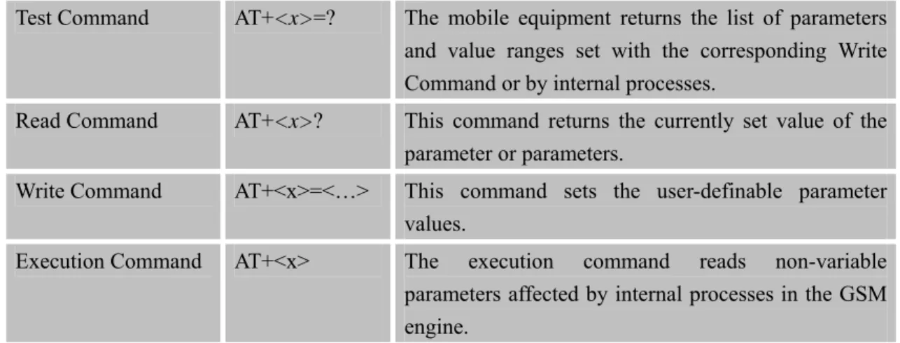
These commands can operate in several modes, as in the following table:
Table 1: Types of AT commands and responses
Test Command AT+<x>=? The mobile equipment returns the list of parameters and value ranges set with the corresponding Write Command or by internal processes.
Read Command AT+<x>? This command returns the currently set value of the parameter or parameters.
Write Command AT+<x>=<…> This command sets the user-definable parameter values.
Execution Command AT+<x> The execution command reads non-variable parameters affected by internal processes in the GSM engine.
1.4.4 Combining AT commands on the same Command line
You can enter several AT commands on the same line. In this case, you do not need to type the "AT" or "at" prefix before every command. Instead, you only need type "AT" or "at" the beginning of the command line. Please note to use a semicolon as the command delimiter after an extended command, for example: ATE1&W&F+ICF?; +CFUN?; &W.
The Command line buffer can accept a maximum of 556 characters. If the characters entered exceeded this number then none of the Command will executed and TA will return "ERROR". 1.4.5 Entering successive AT commands on separate lines
When you need to enter a series of AT commands on separate lines, please Note that you need to wait the final response (for example OK, CME error, CMS error) of last AT Command you entered before you enter the next AT Command.
1.5 Supported character sets
The SIM900 AT Command interface defaults to the IRA character set. The SIM900 supports the following character sets:
• HEX
• IRA
• PCCP • PCDN • 8859-1
The character set can be set and interrogated using the "AT+CSCS" Command (GSM 07.07). The character set is defined in GSM specification 07.05.
The character set affects transmission and reception of SMS and SMS Cell Broadcast messages, the entry and display of phone book entries text field and SIM Application Toolkit alpha strings.
1.6 Flow control
Flow control is very important for correct communication between the GSM engine and DTE. For in the case such as a data or fax call, the sending device is transferring data faster than the receiving side is ready to accept. When the receiving buffer reaches its capacity, the receiving device should be capable to cause the sending device to pause until it catches up.
There are basically two approaches to achieve data flow control: software flow control and hardware flow control. SIM900 support both two kinds of flow control.
In Multiplex mode, it is recommended to use the hardware flow control.
1.6.1 Software flow control (XON/XOFF flow control)
Software flow control sends different characters to stop (XOFF, decimal 19) and resume (XON, decimal 17) data flow. It is quite useful in some applications that only use three wires on the serial interface.
The default flow control approach of SIM900 is hardware flow control (RTS/CTS flow control), to enable software flow control in the DTE interface and within GSM engine, type the following AT Command:
AT+IFC=1, 1
This setting is stored volatile, for use after restart, AT+IFC=1, 1 should be stored to the user profile with AT&W.
NOTE:
The AT commands listed in the table of AT&W chapter should be stored to user profile with
AT&W for use after restart. Most other AT commands in V.25, 07.05, 07.07, GPRS will store
parameters automatically and can be used after module restart.
Ensure that any communications software package (e.g. Hyper terminal) uses software flow control.
NOTE:
received (e.g. TCP/IP) as the DTE interface may interpret binary data as flow control characters.
1.6.2 Hardware flow control (RTS/CTS flow control)
Hardware flow control achieves the data flow control by controlling the RTS/CTS line. When the data transfer should be suspended, the CTS line is set inactive until the transfer from the receiving buffer has completed. When the receiving buffer is ok to receive more data, CTS goes active once again.
To achieve hardware flow control, ensure that the RTS/CTS lines are present on your application platform.
2 AT Commands According to V.25TER
These AT Commands are designed according to the ITU-T (International Telecommunication Union, Telecommunication sector) V.25ter document.
2.1 Overview of AT Commands According to V.25TER
Command Description
A/ RE-ISSUES THE LAST COMMAND GIVEN
ATA ANSWER AN INCOMING CALL
ATD MOBILE ORIGINATED CALL TO DIAL A NUMBER
ATD><N> ORIGINATE CALL TO PHONE NUMBER IN CURRENT MEMORY ATD><STR> ORIGINATE CALL TO PHONE NUMBER IN MEMORY WHICH
CORRESPONDS TO FIELD <STR>
ATDL REDIAL LAST TELEPHONE NUMBER USED
ATE SET COMMAND ECHO MODE
ATH DISCONNECT EXISTING CONNECTION
ATI DISPLAY PRODUCT IDENTIFICATION INFORMATION
ATL SET MONITOR SPEAKER LOUDNESS
ATM SET MONITOR SPEAKER MODE
+++ SWITCH FROM DATA MODE OR PPP ONLINE MODE TO
COMMAND MODE
ATO SWITCH FROM COMMAND MODE TO DATA MODE
ATP SELECT PULSE DIALLING
ATQ SET RESULT CODE PRESENTATION MODE
ATS0 SET NUMBER OF RINGS BEFORE AUTOMATICALLY
ANSWERING THE CALL
ATS3 SET COMMAND LINE TERMINATION CHARACTER
ATS4 SET RESPONSE FORMATTING CHARACTER
ATS5 SET COMMAND LINE EDITING CHARACTER
ATS6 PAUSE BEFORE BLIND DIALLING
ATS7 SET NUMBER OF SECONDS TO WAIT FOR CONNECTION
COMPLETION
ATS8 SET NUMBER OF SECONDS TO WAIT FOR COMMA DIAL
MODIFIER ENCOUNTERED IN DIAL STRING OF D COMMAND
ATS10 SET DISCONNECT DELAY AFTER INDICATING THE ABSENCE OF
DATA CARRIER
ATT SELECT TONE DIALING
ATV TA RESPONSE FORMAT
PROGRESS
ATZ RESET DEFAULT CONFIGURATION
AT&C SET DCD FUNCTION MODE
AT&D SET DTR FUNCTION MODE
AT&F FACTORY DEFINED CONFIGURATION
AT&V DISPLAY CURRENT CONFIGURATION
AT&W STORE ACTIVE PROFILE
AT+GCAP REQUEST COMPLETE TA CAPABILITIES LIST
AT+GMI REQUEST MANUFACTURER IDENTIFICATION
AT+GMM REQUEST TA MODEL IDENTIFICATION
AT+GMR REQUEST TA REVISION IDENTIFICATION OF SOFTWARE
RELEASE
AT+GOI REQUEST GLOBAL OBJECT IDENTIFICATION
AT+GSN REQUEST TA SERIAL NUMBER IDENTIFICATION (IMEI)
AT+ICF SET TE-TA CONTROL CHARACTER FRAMING
AT+IFC SET TE-TA LOCAL DATA FLOW CONTROL
AT+IPR SET TE-TA FIXED LOCAL RATE
AT+HVOIC DISCONNECT VOICE CALL ONLY
2.2 Detailed Description of AT Commands According to V.25TER
2.2.1 A/ Re-issues the Last Command Given A/ Re-issues the Last Command Given Execution
Command A/
Response
Re-issues the previous Command
Reference V.25ter
Note
2.2.2 ATA ANSWER AN INCOMING CALL ATA ANSWER AN INCOMING CALL
Execution Command ATA
Response
TA sends off-hook to the remote station.
Note1: Any additional commands on the same Command line are ignored. Note2: This Command may be aborted generally by receiving a character during execution. The aborting is not possible during some states of connection establishment such as handshaking.
Response in case of data call, if successfully connected
CONNECT<text> TA switches to data mode.
Note: <text> output only if ATX<value> parameter setting with the <value>>0
When TA returns to Command mode after call release OK
Response in case of voice call, if successfully connected OK Response if no connection NO CARRIER Reference V.25ter Note
See also ATX
2.2.3 ATD Mobile Originated Call to Dial A Number ATD Mobile Originated Call to Dial A Number Execution
Command ATD<n>[<mgsm ][;]
Response
This Command can be used to set up outgoing voice, data or fax calls. It also serves to control supplementary services.
Note: This Command may be aborted generally by receiving an ATH Command or a character during execution. The aborting is not possible during some states of connection establishment such as handshaking.
If no dial tone and (parameter setting ATX2 or ATX4) NO DIALTONE
If busy and (parameter setting ATX3 or ATX4) BUSY
If a connection cannot be established NO CARRIER
If the remote station does not answer NO ANSWER
If connection successful and non-voice call.
CONNECT<text> TA switches to data mode.
Note: <text> output only if ATX<value> parameter setting with the <value> >0
When TA returns to Command mode after call release OK
If connection successful and voice call OK
Parameters
<n> String of dialing digits and optionally V.25ter modifiers dialing
digits:
0-9, * , #, +, A, B, C
Following V.25ter modifiers are ignored: ,(comma), T, P, !, W, @
Emergency call:
<n> Standardized emergency number 112 (no SIM needed)
<mgsm> String of GSM modifiers:
I Actives CLIR (Disables presentation of own number to called party)
i Deactivates CLIR (Enable presentation of own number to called party)
G Activates Closed User Group invocation for this call only
g Deactivates Closed User Group invocation for this call only
<;> Only required to set up voice call , return to Command state
Reference V.25ter
Note
z Parameter "I" and "i" only if no *# code is within the dial string
z <n> is default for last number that can be dialed by ATDL
z *# codes sent with ATD are treated as voice calls. Therefore, the Command must be terminated with a semicolon ";"
z See ATX Command for setting result code and call monitoring parameters.
Responses returned after dialing with ATD
z For voice call two different responses mode can be determined. TA returns "OK" immediately either after dialing was completed or after the call is established. The setting is controlled by AT+COLP. Factory default is AT+COLP=0, this cause the TA returns "OK" immediately
after dialing was completed, otherwise TA will returns "OK", "BUSY", "NO DIAL TONE", "NO CARRIER".
Using ATD during an active voice call:
z When a user originates a second voice call while there is already an active voice call, the first call will be automatically put on hold.
z The current states of all calls can be easily checked at any time by using the AT+CLCC Command.
2.2.4 ATD><n> Originate Call to Phone Number in Current Memory ATD><n> Originate Call to Phone Number in Current Memory Execution
Command ATD><n>[<clir> ][<cug>][;]
Response
This Command can be used to dial a phone number from current phonebook memory.
Note: This Command may be aborted generally by receiving an ATH Command or a character during execution. The aborting is not possible during some states of connection establishment such as handshaking.
If error is related to ME functionality +CME ERROR: <err>
If no dial tone and (parameter setting ATX2 or ATX4)
NO DIALTONE
If busy and (parameter setting ATX3 or ATX4) BUSY
If a connection cannot be established NO CARRIER
If the remote station does not answer NO ANSWER
If connection successful and non-voice call.
CONNECT<text>TA switches to data mode.
Note: <text> output only if ATX<value> parameter setting with the <value> >0
When TA returns to Command mode after call release OK
OK Parameters
<n> Integer type memory location should be in the range of
locations available in the memory used
<mgsm> String of GSM modifiers:
<clir>
I Override the CLIR supplementary service subscription default value for this call
Invocation (restrict CLI presentation)
i Override the CLIR supplementary service subscription default value for this call
Suppression (allow CLI presentation) <cug>
G Control the CUG supplementary service information for this call
CUG Not supported
g Control the CUG supplementary service information for this call
CUG Not supported
<;> Only required to set up voice call , return to Command state
Reference V.25ter
Note
z Parameter "I" and "i" only if no *# code is within the dial string z *# codes sent with ATD are treated as voice calls. Therefore, the
Command must be terminated with a semicolon ";"
z See ATX Command for setting result code and call monitoring parameters.
2.2.5 ATD><str> Originate Call to Phone Number in Memory Which Corresponds to Field <str>
ATD><str> Originate Call to Phone Number in Memory Which Corresponds to Field <str> Execution Command ATD><str>[<clir >][<cug>][;] Response
This Command make the TAattempts to set up an outgoing call to stored number.
All available memories are searched for the entry <str>.
Note: This Command may be aborted generally by receiving an ATH Command or a character during execution. The aborting is not possible during some states of connection establishment such as handshaking.
If error is related to ME functionality +CME ERROR: <err>
NO DIALTONE
If busy and (parameter setting ATX3 or ATX4) BUSY
If a connection cannot be established NO CARRIER
If the remote station does not answer NO ANSWER
If connection successful and non-voice call.
CONNECT<text>TA switches to data mode.
Note: <text> output only if ATX<value> parameter setting with the <value> >0
When TA returns to Command mode after call release OK
If successfully connected and voice call OK
Parameters
<str> String type (string should be included in quotation marks)
value ("x"), which should equal to an alphanumeric field in at least one phone book entry in the searched memories. str formatted as current TE character set specified by +CSCS.
<mgsm> String of GSM modifiers:
I Actives CLIR (Disables presentation of own number to called party)
i Deactivates CLIR (Enable presentation of own number to called party)
G Activates Closed User Group invocation for this call only
g Deactivates Closed User Group invocation for this call only
<;> only required to set up voice call , return to Command state Reference
V.25ter
Note
z Parameter "I" and "i" only if no *# code is within the dial string z *# codes sent with ATD are treated as voice calls. Therefore, the
Command must be terminated with a semicolon ";"
z See ATX Command for setting result code and call monitoring parameters.
2.2.6 ATDL Redial Last Telephone Number Used ATDL Redial Last Telephone Number Used Execution
Command ATDL
Response
This Command redials the last voice and data call number used.
Note: This Command may be aborted generally by receiving an ATH Command or a character during execution. The aborting is not possible during some states of connection establishment such as handshaking.
If error is related to ME functionality +CME ERROR: <err>
If no dial tone and (parameter setting ATX2 or ATX4)
NO DIALTONE
If busy and (parameter setting ATX3 or ATX4) BUSY
If a connection cannot be established NO CARRIER
If the remote station does not answer NO ANSWER
If connection successful and non-voice call.
CONNECT<text>TA switches to data mode.
Note: <text> output only if ATX<value> parameter setting with the <value> >0
When TA returns to Command mode after call release OK
If successfully connected and voice call OK
Reference V.25ter
Note
z See ATX Command for setting result code and call monitoring parameters.
z Return the numbers and symbols which ATD supports if there is no last dialing context.
2.2.7 ATE Set Command Echo Mode ATE Set Command Echo Mode Execution Response
This setting determines whether or not the TA echoes characters received from TE during Command state.
OK Command
ATE<value>
Parameter
<value> 0 Echo mode off
1 Echo mode on Reference
V.25ter
Note
2.2.8 ATH Disconnect Existing Connection ATH Disconnect Existing Connection
Response
Disconnect existing call by local TE from Command line and terminate call OK
Note: OK is issued after circuit 109(DCD) is turned off, if it was previously on.
Execution Command ATH[n]
Parameter
<n> 0 Disconnect ALL calls on the channel the command is
requested. All active or waiting calls, CS data calls, GPRS call of the channel will be disconnected.
1 Disconnect all calls on ALL connected channels. All active or waiting calls, CSD calls, GPRS call will be disconnected. (clean up of all calls of the ME)
2 Disconnect all connected CS data call only on the channel the command is requested. (speech calls (active or waiting) or GPRS calls are not disconnected)
3 Disconnect all connected GPRS calls only on the channel the command is requested (speech calls (active or waiting) or CS data calls are not disconnected.
4 Disconnect all CS calls (either speech or data) but does not disconnect waiting call (either speech or data) on the channel the command is requested.
5 Disconnect waiting call (either speech or data) but does not disconnect other active calls (either CS speech, CS data or GPRS) on the channel the command is requested.
(rejection of incoming call) Reference
V.25ter
2.2.9 ATI Display Product Identification Information ATI Display Product Identification Information Execution
Command ATI
Response
TA issues product information text Example: SIM900 R11.0 OK Reference V.25ter Note
2.2.10 ATL Set Monitor speaker loudness ATL Set Monitor speaker loudness
Response OK Execution Command ATL<value> Parameter <value> 0..9 volume Reference V.25ter Note No effect in GSM
2.2.11 ATM Set Monitor Speaker Mode ATM Set Monitor Speaker Mode
Response OK Execution Command ATM<value> Parameter <value> 0..9 mode Reference V.25ter Note No effect in GSM
2.2.12 +++ Switch from Data Mode or PPP Online Mode to Command Mode
+++ Switch from Data Mode or PPP Online Mode to Command Mode
Execution Command +++
Response
The +++ character sequence causes the TA to cancel the data flow over the AT interface and switch to Command mode. This allows you to enter AT Command while maintaining the data connection to the remote server. OK
To prevent the +++ escape sequence from being misinterpreted as data, it should comply to following sequence:
1. No characters entered for T1 time (1 second)
2. "+++" characters entered with no characters in between (0.5 second) 3. No characters entered for T1 timer (0.5 second)
4. Switch to Command mode, otherwise go to step 1. Parameter
Reference V.25ter
Note
To return from Command mode back to data mode: Enter ATO.
2.2.13 ATO Switch from Command Mode to Data Mode ATO Switch from Command Mode to Data Mode
Response
TA resumes the connection and switches back from Command mode to data mode.
CONNECT
If connection is not successfully resumed NO CARRIER
else
TA returns to data mode from Command mode CONNECT <text> Note: <text> only if parameter setting ATX>0
Execution Command ATO[n]
Parameter
<n> 0 Switch from Command mode to data mode.
Reference V.25ter
Note
2.2.14 ATP Select Pulse Dialling ATP Select Pulse Dialling Execution Command ATP Response OK Reference V.25ter Note No effect in GSM
2.2.15 ATQ Set Result Code Presentation Mode ATQ Set Result Code Presentation Mode Execution
Command ATQ<n>
Response
This parameter setting determines whether or not the TA transmits any result code to the TE. Information text transmitted in response is not affected by this setting.
If <n>=0: OK
If <n>=1: (none)
Parameter
<n> 0 TA transmits result code
1 Result codes are suppressed and not transmitted Reference
V.25ter
Note
2.2.16 ATS0 Set Number of Rings before Automatically Answering the Call ATS0 Set Number of Rings before Automatically Answering the Call
Response <n> OK Read Command ATS0? Parameter
See Write Command Response
This parameter setting determines the number of rings before auto-answer. OK
ERROR Write Command
ATS0=<n>
Parameter
<n> 0 Automatic answering is disable.
1-255 Number of rings the modem will wait for before answering the phone if a ring is detected.
Reference V.25ter
Note
If <n>is set too high, the calling party may hang up before the call can be answered automatically.
2.2.17 ATS3 Set Command Line Termination Character ATS3 Set Command Line Termination Character
Response <n> OK Read Command ATS3? Parameter
See Write Command Write Command
ATS3=<n>
Response
terminate an incoming Command line. The TA also returns this character in output.
OK
ERROR Parameter
<n> 13 Command line termination character
Reference V.25ter
Note
Default 13 = CR. It only supports default value.
2.2.18 ATS4 Set Response Formatting Character ATS4 Set Response Formatting Character
Response <n> OK Read Command ATS4? Parameter
See Write Command Response
This parameter setting determines the character generated by the TA for result code and information text.
OK
ERROR Write Command
ATS4=<n>
Parameter
<n> 10 Response formatting character Reference
V.25ter
Note
Default 10 = LF. It only supports default value.
2.2.19 ATS5 Set Command Line Editing Character ATS5 Set Command Line Editing Character
Response <n> OK Read Command ATS5? Parameter
See Write Command Write Command
ATS5=<n>
Response
This parameter setting determines the character recognized by TA as a request to delete from the Command line the immediately preceding
character. OK
ERROR Parameter
<n> 0-8-127 Response formatting character
Reference V.25ter
Note
Default 8 = Backspace.
2.2.20 ATS6 Pause Before Blind Dialling ATS6 Pause Before Blind Dialling Read Command ATS6? Response ERROR Response OK ERROR Write Command ATS6=<n> Parameter <n> 0..999 Time Reference V.25ter Note No effect in GSM
2.2.21 ATS7 Set Number of Seconds to Wait for Connection Completion ATS7 Set Number of Seconds to Wait for Connection Completion
Response <n> OK Read Command ATS7? Parameter
See Write Command Response
This parameter setting determines the amount of time to wait for the connection completion in case of answering or originating a call. OK
ERROR Write Command
ATS7=<n>
Parameter
<n> 1-60-255 Number of seconds to wait for connection completion
V.25ter z If called party has specified a high value for ATS0=<n>, call setup may fail.
z The correlation between ATS7 and ATS0 is important z Example: Call may fail if ATS7=30 and ATS0=20. z ATS7 is only applicable to data call.
2.2.22 ATS8 Set Number of Seconds to Wait for Comma Dial Modifier Encountered in Dial String of D Command
ATS8 Set Number of Seconds to Wait for Comma Dial Modifier Encountered in Dial String of D Command Response <n> OK Read Command ATS8? Parameter
See Write Command Response OK ERROR Write Command ATS8=<n> Parameter
<n> 0-255 The value of this register determines how long the modem
should pause when it sees a comma in the dialing string. Reference
V.25ter
Note
No effect in GSM
2.2.23 ATS10 Set Disconnect Delay after Indicating the Absence of Data Carrier ATS10 Set Disconnect Delay after Indicating the Absence of Data Carrier
Response <n> OK Read Command ATS10? Parameter
See Write Command Response
This parameter setting determines the amount of time that the TA will remain connected in absence of data carrier. If the data carrier is once more detected before disconnecting, the TA remains connected.
OK ERROR Write Command
ATS10=<n>
<n> 1-15-254 Number of tenths seconds of delay Reference
V.25ter
Note
2.2.24 ATT Select Tone Dialing ATT Select Tone Dialing Execution Command ATT Response OK Reference V.25ter Note No effect in GSM
2.2.25 ATV TA Response Format ATV TA Response Format
Response
This parameter setting determines the contents of the header and trailer transmitted with result codes and information responses.
When<value>=0 0 When<value>=1 OK Execution Command ATV<value> Parameter
<value> 0 Information response: <text><CR><LF> Short result code format: <numeric code><CR> 1 Information response: <CR><LF><text><CR><LF>
Long result code format: <CR><LF><verbose code> <CR><LF>
The result codes, their numeric equivalents and brief descriptions of the use of each are listed in the following table.
Reference V.25ter
Note
ATV1 ATV0 Description
OK 0 Acknowledges execution of a Command
CONNECT 1 A connection has been established; the DCE is moving from Command state to online data state
RING 2 The DCE has detected an incoming call signal from
network
NO CARRIER 3 The connection has been terminated or the attempt to establish a connection failed
length exceeded, parameter value invalid, or other problem with processing the Command line
NO DIALTONE 6 No dial tone detected
BUSY 7 Engaged (busy) signal detected
NO ANSWER 8 "@" (Wait for Quiet Answer) dial modifier was used, but remote ringing followed by five seconds of silence was not detected before expiration of the connection timer (S7)
PROCEEDING 9 An AT command is being processed
CONNECT <text>
Manufacturer- specific
Same as CONNECT, but includes manufacturer-specific text that may specify DTE speed, line speed, error control, data compression, or other status
2.2.26 ATX Set CONNECT Result Code Format and Monitor Call Progress ATX Set CONNECT Result Code Format and Monitor Call Progress
Response
This parameter setting determines whether or not the TA detected the presence of dial tone and busy signal and whether or not TA transmits particular result codes.
OK ERROR Execution Command ATX<value> Parameter
<value> 0 CONNECT result code only returned, dial tone and busy
detection are both disabled.
1 CONNECT<text> result code only returned, dial tone and
busy detection are both disabled.
2 CONNECT<text> result code returned, dial tone
detection is enabled, busy detection is disabled.
3 CONNECT<text> result code returned, dial tone
detection is disabled, busy detection is enabled.
4 CONNECT<text> result code returned, dial tone and
busy detection are both enabled. Reference
V.25ter
Note
2.2.27 ATZ Reset Default Configuration ATZ Reset Default Configuration Execution
Command ATZ[<value>]
Response
TA sets all current parameters to the user defined profile. OK
ERROR Parameter
<value> 0 Restore profile 0 1 Restore profile 1 Reference
V.25ter
Note
Parameter impacted by Z command:
Command Parameter name Default value
ATE <echo> 0x01 ATQ <result> 0x00 ATV <format> 0x01 ATX <result> 0x04 AT&C <behavior> 0x01 AT&D <behavior> 0x01 AT+IFC <TA_by_TE> 0x00 AT+IFC <TE_by_TA> 0x00 AT+FCLASS <class> 0x00 ATS0 <num> 0x00 ATS3 <char> 0x00 ATS4 <char> 0x0D
ATS5 <char> 0x0A
ATS7 <time> 0x08
ATS8 <time> 0x32
ATS10 <time> 0x0E
2.2.28 AT&C Set DCD Function Mode AT&C Set DCD Function Mode
Response
This parameter determines how the state of circuit 109 (DCD) relates to the detection of received line signal from the distant end.
OK ERROR Execution Command AT&C[<value>] Parameter
<value> 0 DCD line is always ON
1 DCD line is ON only in the presence of data carrier Reference
V.25ter
2.2.29 AT&D Set DTR Function Mode AT&D Set DTR Function Mode
Response
This parameter determines how the TA responds when circuit 108/2 (DTR) is changed from the ON to the OFF condition during data mode.
OK ERROR Execution Command AT&D[<value>] Parameter
<value> 0 TA ignores status on DTR.
1 ON->OFF on DTR: Change to Command mode with remaining the connected call.
2 ON->OFF on DTR: Disconnect call, change to Command mode. During state DTR = OFF is auto-answer off. Reference
V.25ter
Note
2.2.30 AT&F Factory Defined Configuration AT&F Factory Defined Configuration
Response
TA sets all current parameters to the manufacturer defined profile. OK
Execution Command AT&F[<value>]
Parameter
<value> 0 Set all TA parameters to manufacturer defaults.
Reference V.25ter
Note
Parameter impacted by &F command:
Command Parameter name Default value
ATE <echo> 0x01 ATQ <result> 0x00 ATV <format> 0x01 ATX <result> 0x04 AT+IFC <TA_by_TE> 0x00 AT+IFC <TE_by_TA> 0x00 ATS0 <num> 0x00 ATS3 <char> 0x0D
ATS4 <char> 0x0A
ATS7 <time> 0x64
ATS8 <time> 0x02
ATS10 <time> 0x0E
AT+CRLP <ver> 0x00 AT+CRLP <T4> 0x07 AT+CRLP <iws> 0x61 AT+CRLP <mws> 0x61 AT+CRLP <T1> 0x48 AT+CRLP <N2> 0x06 AT+CPBS <storage> 0x53 0x4D 0x00 AT+CSMP <fo> 0x11 AT+CSMP <vp> 0x00 AT+CSMP <vp> 0x18 AT+CSMP <vp> 0x00 AT+CSMP <vp> 0x00 AT+CSMP <fo> 0x11 AT+CSMP <vp> 0x00 AT+CSMP <vp> 0x18 AT+CSMP <vp> 0x00 AT+CSMP <vp> 0x00 AT+CSMP <fo> 0x11 AT+CSMP <vp> 0x00 AT+CSMP <vp> 0x18 AT+CSMP <vp> 0x00 AT+CSMP <vp> 0x00 AT+CSMP <vp> 0x00..0x00 AT+CSMP <pid> 0x00 AT+CSMP <dcs> 0x00 AT+CR <mode> 0x00 AT+CSTA <type> 0x81 AT+CBST <speed> 0x05 0x02 0x00 AT+CBST <name> 0x01 0x00 AT+CBST <ce> 0x01 AT+CRC <mode> 0x00 AT+CMOD <mode> 0x00 AT+CMEE <n> 0x00 AT+CREG <n> 0x00 AT+CGREG <n> 0x00
AT+CSMS <service> 0x00 AT+CMGF <mode> 0x00 AT+CSDH <show> 0x00 AT+CSCS <chset> 0x00 AT+CLIR <n> 0x00 AT+CLIP <n> 0x00 AT+COLP <n> 0x00
2.2.31 AT&V Display Current Configuration AT&V Display Current Configuration
Response
TA returns the current parameter setting. <current configurations text>
OK ERROR Execution Command AT&V[<n>] Parameter
<n> 0 Responses in numeric format
Reference V.25ter
Note
2.2.32 AT&W Store Active Profile AT&W Store Active Profile
Response
TA stores the current parameter setting in the user defined profile. OK ERROR Execution Command AT&W[<n>] Parameter
<n> 0 Store the current configuration in profile 0
1 Store the current configuration in profile 1 Reference
V.25ter
Note
The user defined profile is stored in non volatile memory.
Parameter stored by &W
Command Parameter name Displayedby &V
ATE <echo> Y
ATQ <result> Y
ATV <format> Y
AT&C <behavior> Y AT&D <behavior> Y AT+IFC <TA_by_TE> Y AT+IFC <TE_by_TA> Y AT+FCLASS <class> Y ATS0 <num> Y ATS3 <char> Y ATS4 <char> Y ATS5 <char> Y ATS7 <time> Y ATS8 <time> Y ATS10 <time> Y
2.2.33 AT+GCAP Request Complete TA Capabilities List AT+GCAP Request Complete TA Capabilities List
Response
TA reports a list of additional capabilities.
+GCAP: list of supported <name>s
OK Execution
Command AT+GCAP
Parameter
<name> +CGSM GSM function is supported
+FCLASS FAX function is supported Reference
V.25ter
Note
The command can be executed only when the SIM card is present.
2.2.34 AT+GMI Request Manufacturer Identification AT+GMI Request Manufacturer Identification
Response OK Test Command AT+GMI=? Parameter Execution Command AT+GMI
TA reports one or more lines of information text which permit the user to identify the manufacturer.
SIMCOM_Ltd
OK
Reference V.25ter
2.2.35 AT+GMM Request TA Model Identification AT+GMM Request TA Model Identification Test Command
AT+GMM=?
Response OK
TA reports one or more lines of information text which permit the user to identify the specific model of device.
<model> OK Execution Command AT+GMM Parameter
<model> product model identification text
Reference V.25ter
Note
2.2.36 AT+GMR Request TA Revision Identification of Software Release AT+GMR Request TA Revision Identification of Software Release Test Command
AT+GMR=?
Response OK
TA reports one or more lines of information text which permit the user to identify the revision of software release.
Revision:<revision> OK Execution Command AT+GMR Parameter
<revision> Revision of software release
Reference V.25ter
Note
2.2.37 AT+GOI Request Global Object Identification AT+GOI Request Global Object Identification Test Command AT+GOI=? Response OK Execution Command AT+GOI Response
TA reports one or more lines of information text which permit the user to identify the device, based on the ISO system for registering unique object identifiers.
OK Parameter
<Object Id> identifier of device type
see X.208, 209 for the format of <Object Id> Reference
V.25ter
Note
2.2.38 AT+GSN Request TA Serial Number Identification (IMEI) AT+GSN Request TA Serial Number Identification(IMEI) Test Command
AT+GSN=?
Response OK Response
TA reports the IMEI (international mobile equipment identifier) number in information text which permit the user to identify the individual ME device. <sn> OK Execution Command AT+GSN Parameter
<sn> IMEI of the telephone(International Mobile station Equipment
Identity) Reference
V.25ter
Note
The serial number (IMEI) is varied by individual ME device.
2.2.39 AT+ICF Set TE-TA Control Character Framing AT+ICF Set TE-TA Control Character Framing
Response
+ICF:(list of supported <format>s),(list of supported <parity>s) OK
Test Command AT+ICF=?
Parameters
See Write Command Response +ICF: <format>,<parity> OK Read Command AT+ICF? Parameters
See Write Command Write Command
AT+ICF=<forma t>,[<parity>]
Response
This parameter setting determines the serial interface character framing format and parity received by TA from TE.
OK Parameters
<format> 1 8 data 0 parity 2 stop
2 8 data 1 parity 1 stop 3 8 data 0 parity 1 stop 4 7 data 0 parity 2 stop 5 7 data 1 parity 1 stop 6 7 data 0 parity 1 stop
<parity> 0 odd 1 even 3 space (0) Reference V.25ter Note
z The Command is applied for Command state; z In <format> parameter, "0 parity" means no parity;
z The <parity> field is ignored if the <format>field specifies no parity
and string "+ICF: <format>,255" will be response to AT+ICF? Command.
2.2.40 AT+IFC Set TE-TA Local Data Flow Control
AT+IFC Set TE-TA Local Data Flow Control
Response
+IFC: (list of supported <dce_by_dte>s),(list of supported
<dte_by_dce>s) OK
Test Command AT+IFC=?
Parameters
See Write Command Response +IFC: <dce_by_dte>,<dte_by_dce> OK Read Command AT+IFC? Parameters
See Write Command Response
This parameter setting determines the data flow control on the serial interface for data mode.
OK Write Command AT+IFC=<dce_b y_dte>[,<dte_by _dce>] Parameters
<dce_by_dte> Specifies the method will be used by TE at receive of
data from TA 0 No flow control
1 Software flow control 2 Hardware flow control
<dte_by_dce> Specifies the method will be used by TA at receive of
data from TE 0 No flow control 1 Software flow control 2 Hardware flow control Reference
V.25ter
Note
2.2.41 AT+IPR Set TE-TA Fixed Local Rate AT+IPR Set TE-TA Fixed Local Rate
Response
+IPR: (),(list of supported <rate>s) OK
Test Command AT+IPR=?
Parameter
See Write Command Response +IPR: <rate> OK Read Command AT+IPR? Parameter
See Write Command Response
This parameter setting determines the data rate of the TA on the serial interface. The rate of Command takes effect following the issuance of any result code associated with the current Command line.
OK Write Command AT+IPR=<rate>
Parameter
<rate> Baud rate per second 0 (Auto-bauding) 1200 2400 4800 9600 19200 38400 57600 115200
Reference V.25ter
Note
Factory setting is AT+IPR=0(auto-bauding).
2.2.41.1 Auto-bauding
Synchronization between DTE and DCE ensure that DTE and DCE are correctly synchronized and the baud rate used by the DTE is detected by the DCE (= ME). To allow the baud rate to be synchronized, simply issue an "AT" string. This is necessary when you start up the module while auto-bauding is enabled. It is recommended to wait 3 to 5 seconds before sending the first AT character. Otherwise undefined characters might be returned.
If you want to use auto-bauding and auto-answer at the same time, you can easily enable the DTE-DCE synchronization, when you activate auto-bauding first and then configure the auto-answer mode.
Restrictions on auto-bauding operation
z The serial interface has to be operated at 8 data bits, no parity and 1 stop bit (factory setting).
z Only the strings "AT" or "At" (not "aT" or "at") can be detected when auto-bauding is enabled.
z AT+IPR=0 setting to auto-bauding will take effect after module resets. If user wants to change DTE baud rate during module is running, i.e. from 57600 to 4800, DTR shall be used to urge auto-bauding progress. DTR shall be pulled up to invalid state at least 2 seconds by DTE and then pulled down to valid state. The step will urge auto-bauding progress and DCE will synchronize its baud rate after it receives data from the serial port. z Unsolicited Result Codes that may be issued before the ME detects the new baud rate (by
receiving the first AT Command string) will be sent at the previously detected baud rate. z The Unsolicited Result Codes "RDY" and so on are not indicated when you start up the ME
while auto-bauding is enabled.
z It is not recommended to switch to auto-bauding from a baud rate that cannot be detected by the auto-bauding mechanism (e.g. 300 baud). Responses to +IPR=0 and any commands on the same line might be corrupted.
Auto-bauding and baud rate after restart
The most recently detected baud rate can not be stored when module is powered down. 2.2.42 AT+HVOIC Disconnect Voice Call Only
AT+HVOIC Disconnect Voice Call Only Execution
Command AT+HVOIC
Response
Disconnect existing voice call by local TE from Command line and terminate call with existing PPP or CSD connection on.
OK Reference
V.25ter
3 AT Commands According to GSM07.07
3.1 Overview of AT Command According to GSM07.07
Command Description
AT+CACM ACCUMULATED CALL METER(ACM) RESET OR QUERY
AT+CAMM ACCUMULATED CALL METER MAXIMUM(ACM MAX) SET OR
QUERY
AT+CAOC ADVICE OF CHARGE
AT+CBST SELECT BEARER SERVICE TYPE
AT+CCFC CALL FORWARDING NUMBER AND CONDITIONS CONTROL
AT+CCWA CALL WAITING CONTROL
AT+CEER EXTENDED ERROR REPORT
AT+CGMI REQUEST MANUFACTURER IDENTIFICATION
AT+CGMM REQUEST MODEL IDENTIFICATION
AT+CGMR REQUEST TA REVISION IDENTIFICATION OF SOFTWARE
RELEASE
AT+CGSN REQUEST PRODUCT SERIAL NUMBER IDENTIFICATION
(IDENTICAL WITH +GSN)
AT+CSCS SELECT TE CHARACTER SET
AT+CSTA SELECT TYPE OF ADDRESS
AT+CHLD CALL HOLD AND MULTIPARTY
AT+CIMI REQUEST INTERNATIONAL MOBILE SUBSCRIBER IDENTITY
AT+CLCC LIST CURRENT CALLS OF ME
AT+CLCK FACILITY LOCK
AT+CLIP CALLING LINE IDENTIFICATION PRESENTATION AT+CLIR CALLING LINE IDENTIFICATION RESTRICTION
AT+CMEE REPORT MOBILE EQUIPMENT ERROR
AT+COLP CONNECTED LINE IDENTIFICATION PRESENTATION
AT+COPS OPERATOR SELECTION
AT+CPAS PHONE ACTIVITY STATUS
AT+CPBF FIND PHONEBOOK ENTRIES
AT+CPBR READ CURRENT PHONEBOOK ENTRIES
AT+CPBS SELECT PHONEBOOK MEMORY STORAGE
AT+CPBW WRITE PHONEBOOK ENTRY
AT+CPIN ENTER PIN
AT+CPWD CHANGE PASSWORD
AT+CR SERVICE REPORTING CONTROL
INDICATION
AT+CREG NETWORK REGISTRATION
AT+CRLP SELECT RADIO LINK PROTOCOL PARAMETERS
AT+CRSM RESTRICTED SIM ACCESS
AT+CSQ SIGNAL QUALITY REPORT
AT+FCLASS FAX: SELECT, READ OR TEST SERVICE CLASS
AT+FMI FAX: REPORT MANUFACTURED ID
AT+FMM FAX: REPORT MODEL ID
AT+FMR FAX: REPORT REVISION ID
AT+VTD TONE DURATION
AT+VTS DTMF AND TONE GENERATION
AT+CMUX MULTIPLEXER CONTROL
AT+CNUM SUBSCRIBER NUMBER
AT+CPOL PREFERRED OPERATOR LIST
AT+COPN READ OPERATOR NAMES
AT+CFUN SET PHONE FUNCTIONALITY
AT+CCLK CLOCK
AT+CSIM GENERIC SIM ACCESS
AT+CALM ALERT SOUND MODE
AT+CALS ALERT SOUND SELECT
AT+CRSL RINGER SOUND LEVEL
AT+CLVL LOUD SPEAKER VOLUME LEVEL
AT+CMUT MUTE CONTROL
AT+CPUC PRICE PER UNIT AND CURRENCY TABLE
AT+CCWE CALL METER MAXIMUM EVENT
AT+CBC BATTERY CHARGE
AT+CUSD UNSTRUCTURED SUPPLEMENTARY SERVICE DATA
AT+CSSN SUPPLEMENTARY SERVICES NOTIFICATION
3.2 Detailed Descriptions of AT Command According to GSM07.07
3.2.1 AT+CACM Accumulated Call Meter (ACM) Reset or Query AT+CACM Accumulated Call Meter(ACM) Reset or Query Test Command AT+CACM=? Response OK Read Command AT+CACM? Response
+CACM: <acm>
OK
If error is related to ME functionality: +CME ERROR: <err>
Parameter
<acm> string type (string should be included in quotation marks);
three bytes of the current ACM value in hexa-decimal format (e.g. "00001E" indicates decimal value 30)
000000 – FFFFFF Response
TA resets the Advice of Charge related accumulated call meter (ACM) value in SIM file EF (ACM). ACM contains the total number of home units for both the current and preceding calls.
OK
If error is related to ME functionality: +CME ERROR: <err>
Write Command AT+CACM=<pa sswd>
Parameter
<passwd> string type (string should be included in quotation marks):
SIM PIN2 Reference
GSM 07.07 [13]
Note
3.2.2 AT+CAMM Accumulated Call Meter Maximum (ACM max) Set or Query AT+CAMM Accumulated Call Meter Maximum(ACM max) Set or Query Test Command
AT+CAMM=?
Response OK Response
TA returns the current value of ACM max.
+CAMM:<acmmax>
OK
If error is related to ME functionality: +CME ERROR: <err>
Read Command AT+CAMM?
Parameters
See Write Command Write Command
AT+CAMM=<ac mmax>[,<passwd
Response
TA sets the Advice of Charge related accumulated call meter maximum value in SIM file EF (ACM max). ACM max contains the maximum