Simulation of VSC Based HVDC Transmission System under Fault
Conditions
K.Sivanagamani*, P.Bhaskar Reddy **
*1
PG Student, Department of EEE, Vikas Group of Institutions, Nunna, Vijayawada , AP, INDIA.
**2Assisctant Professor, Department Of EEE, Vikas Group of Institutions, Nunna, Vijayawada AP, INDIA.
1Email:
1[email protected],
2[email protected]
Abstract: Voltage-source-converter high-voltage dc (VSC-HVDC) transmission systems have evolved from simple two-level converters to neutral-point clamped converters and then to true multilevel converters such as modular converters. Present VSC-HVDC transmission systems rely on their converter station control systems and effective impedance between the point-of-common-coupling (PCC) and the converter terminals to ride-through dc side faults. A VSC-HVDC transmission system is a candidate to meet these challenges due to its operational flexibility, such as provision of voltage support to ac networks, its ability to operate independent of ac network strength therefore makes it suitable for connection of weak ac networks such as offshore wind farms, suitability for multi terminal HVDC network realization as active power reversal is achieved without dc link voltage polarity change, and resiliency to ac side faults. This paper proposes a new breed of high-voltage dc (HVDC) transmission systems based on a hybrid multilevel voltage source converter (VSC) with ac-side cascaded H-bridge cells. This paper assesses its dynamic performance during steady-state and network alterations, including its response to ac and dc side faults by using MAT Lab/Simulink.
Index Terms—DC fault reverse blocking capability, hybrid multilevel converter with ac side cascaded H-bride cells, modular multilevel converter.
I. Introduction
With the development of power electronic technology and the relatively high switching frequency of Pulse Width Modulation (PWM), HVDC transmission system based on Voltage Source Converters (VSCs) has taken on some excellent advantages. The new VSC-HVDC system known as
“HVDC Light” or “HVDC Plus” [1,2] by leading
vendors, has been applied in several special occasions such as the connection of off-shore wind farms or oil drilling platforms into the mainland electrical network and for underground transmission or distribution systems within congested cities. The differences in structure between the two types of converters (Conventional HVDC and VSC-HVDC)
Generally, the new transmission technology has the following advantages compared with conventional, thyristor based HVDC [3-5]:
Possibility to control the reactive power (consumed or generated by the converter) independently of the active power (to or from the converter).
No risk of commutation failures in the converter.
Ability to connect to weak AC networks, or even dead networks.
Faster response due to increased switching frequency (PWM).
Minimal environmental impact.
There are two approaches to assist VSC-HVDC transmission systems to ride-through dc side faults. The first approach is to use a fast acting dc circuit breaker, with considerably high let-through current to tolerate the high dc fault discharge current that may flow in the dc side. This breaker must be capable of operating at high voltage and isolates temporary or permanent dc faults, plus have a relatively high-current-breaking capacity. The second approach is to use converter stations with dc fault reverse-blocking capability [1], [4]. Each converter station must be able to block current flow between the ac and dc sides during a dc fault, allowing dc-side capacitor discharge current, which is the major component of the dc fault current, to decay to zero and then isolate the fault. Several converter topologies with this inherent feature have been proposed, including an H-bridge modular multilevel converter, an alternative arm modular multilevel converter, and a hybrid multilevel converter with ac-side cascaded H-bridge cells. However, the drawback is that the active power exchange between the ac networks reduces to zero during the dc fault period.
Fig.1 shows one phase of a hybrid multilevel VSC with H-bridge cells per phase. It can generate 4n+1
voltage levels at converter terminal “a” relative to supply midpoint “0.” Therefore, with a large number
of cells per phase, the converter presents near pure sinusoidal voltage to the converter transformer as depicted in Fig.1 [1]. The two-level converter that blocks high-voltage controls the fundamental voltage using selective harmonic elimination (SHE) with one notch per quarter cycle, as shown in Fig.1. Therefore, the two-level converter devices operate with 150-Hz switching losses, hence low switching losses and audible noise are expected. The H-bridge cells
between “M” and “a” are operated as a series active
power filter to attenuate the voltage harmonics produced by the two-level converter bridge. These H-bridge cells are controlled using level-shifted carrier-based multilevel pulse width modulation with a 1-kHz switching frequency.
To minimize the conversion losses in the H-bridge cells, the number of cells is reduced such that the voltage across the H-bridge floating capacitors sum to (1/2 Vdc). This may result in a small converter station, because the number of H-bridge cells required per converter with the proposed HVDC system is one quarter of those required for a system based on the modular multilevel converter. With a large number of cells per phase, the voltage waveform generated across the H-bridge cells is as shown in Fig.1, and an effective switching frequency per device of less than 150 Hz is possible. The dc fault reverse-blocking capability of the proposed HVDC system is achieved by inhibiting the gate signals to the converter switches, therefore no direct path exists between the ac and dc side through freewheel diodes, and cell capacitor voltages will oppose any current flow from one side to another. Consequently, with no current flows, there is no active and reactive power exchange between ac and dc side during dc-side faults. This dc fault aspect means transformer coupled H-bridges cannot be used. The ac grid contribution to dc-side fault current is eliminated, reducing the risk of converter failure due to increased current stresses in the switching devices during dc-side faults. From the grid standpoint, the dc fault reverse-blocking capability of the proposed.
Fig.1. Hybrid voltage multilevel converter with ac side cascaded H-bridge cells.
III. Control Systems
A HVDC transmission system based on a hybrid multilevel VSC with ac-side cascaded H-bridge cells requires three control system layers. The inner control layer represents the modulator and capacitor voltage-balancing mechanism that generates the gating signals for the converter switches and maintains voltage balance of the H-bridge cell capacitors. The intermediate control layer represents the current controller that regulates the active and reactive current components over the full operating range and restraints converter station current injection into ac network during network disturbances such as ac and dc side faults. The outer control layer is the dc voltage (or active power) and ac voltage (or reactive power) controller that provide set points to the current controllers. The inner controller has only been discussed to a level appropriate to power systems engineers. The intermediate and outer control layers are presented in detail to give the reader a sense of HVDC control system complexity.
Current Controller Design: The differential equations describing the ac-side transient and steady-state are
(1)
(2) Assume
(3)
The new control variables λdand λqcan be obtained
from two proportion-integral controllers (PI) having the same gains:
(5)
(6) Where ∗ and ∗ represent reference direct and quadrature current components.
To facilitate control design in state space, the integral
parts of λd and λq are replaced by
and ,
rearranged in the following form:
(7)
(8) The integral parts, in differential equations form, are
(9)
(10)
Fig.2. (a) Representation of VSC station and (b) schematic diagram summarizing the control layer of the hybrid multilevel
converter with ac side cascaded H-bridge cells.
IV.Performance Evaluation
The viability of the VSC-HVDC system that uses a
bridge cells is investigated here, with emphasis on its dynamic performance during network alterations. In the steady state, the test network in Fig.3 (a) is used to assess its power control and voltage support capabilities. To further illustrate the advantages of the hybrid multilevel converter during ac and dc network disturbances, the same test network is subjected to a three-phase ac-side fault and a pole-to-pole dc-side fault at locations depicted in Fig. 3, both for a 140-ms duration. Converter stations 1 and 2in Fig. 3 are represented by detailed hybrid VSC models with seven cells per phase, with the controllers in Fig. 2(b) in corporate. Seven cells per arm are used in this paper in order to achieve acceptable simulation times without compromising result accuracy, as each system component is represented in detailed. Also, the hybrid converter with seven H-bridge cells per phase generates 29 voltage levels per phase, which is the same as the two-switch modular multilevel converter with 28 cells per arm, for the same dc link voltage such that devices in both converters experience the same voltage stresses. The converters are configured to regulate active power exchange and dc link voltage, and ac voltage magnitudes at PCC1 and PCC2 respectively.
Fig.3. Test network and waveforms demonstrating the steady-state operation of HVDC system based on hybrid voltage source
multilevel converter with ac side cascaded H-bridge cells. V.Matlab /Simulation Results
Figure: 4Matlab/Simulink model of the steady-state operation of HVDC system based on hybrid voltage source multilevel converter
(b)
(c)
(d)
(e)
(f)
(g)
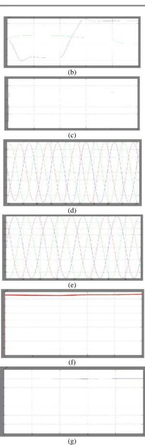
Fig. 5 Test network and waveforms demonstrating the steady-state operation of HVDC system based on hybrid voltage source multilevel converter with ac side cascaded H bridge cells. (a) Active and reactive power converter station 1 exchanges with
PPC1; (b) active and reactive power converter station 2 exchanges with PPC2; (c) voltage magnitude at ppc2 (d) voltage waveforms at PPC2; (e) current waveforms converter station 1 exchange with PPC1 (f) voltage across 21 cell capacitors of the three phases of converter 1 (g) voltage across the dc link of converter station 2.
Figure: 6 Matlab/Simulink model of the ac fault ride-through capability of HVDC transmission systems based on hybrid voltage multilevel converter with ac side Cascaded H-bridge cells.
(a)
(b)
(c)
(e)
(f)
(g)
(h)
(i)
(j)
(k)
(l)
(m)
(n)
(o)
(before transformer). (i) Active and reactive power at PCC1. (j) Active and reactive power at PCC2. Results in (i)–(o) demonstrate the case when the converter stations operate close to their maximum active power capabilities (power command at converter 1 is set to 0.75 pu, which is 515 MW) and system is subjected to a three-phase fault with a 300-ms duration. (k) Voltage magnitude at PCC1. (l) Voltage magnitude at PCC2. (m) Current waveforms converter 2 injects into PCC2. (n) Converter 2 dc link voltage. (o) Voltage across the 21 H-bridge cell capacitors of converter 2. Results in (i)–(o) demonstrate the case when the converter stations operate close to their maximum active power capabilities (power command at converter 1 is set to 0.75 pu, which is 515 MW) and system is subjected to a three-phase fault with a 300-ms duration.
Figure 8 Matlab/Simulink model of dc fault ride-through capability of HVDC transmission systems based on hybrid voltage multilevel converter with ac side cascaded H-bridge cells.
(a)
(b)
(c)
(d)
(e)
(f)
(g)
(h)
(i)
reactive power converter 1 exchanges with PPC1. (b) Active and reactive power converter 2 exchanges with PPC2. (c) Voltage magnitude at PPC1. (d) Voltage magnitude at PPC2. (e) Current waveforms converter 1 exchange with grid G1 at PPC1. (f) Current waveforms converter 2 exchange with grid G2 at PPC2. (g) Converter 2 dc link voltage. (h) Zoomed version of dc link current demonstrating the benefits of dc fault reverse blocking capability. (i) Voltage across the H-bridge cell capacitors of converter 1.
VI.Conclusion
This paper presented a new generation VSC-HVDC transmission system based on a hybrid multilevel converter with ac-side cascaded H-bridge cells. The main advantages of the proposed HVDC system are:
• Potential small footprint and lower semiconductor losses compared to present HVDC systems.
•low filtering requirements on the ac sides and
presents high-quality voltage to the converter transformer.
• does not compromise the advantages of VSC -HVDC systems such as four-quadrant operation; voltage support capability; and black-start capability, which is vital for connection of weak ac networks with no generation and wind farms.
It can be obtained also that during a single-phase fault the transmitted power can be kept constant except a small oscillation during the fault. However, during a three-phase fault; the decreased voltage at the converter terminals strongly reduces the power flow by the DC link. When the fault is cleared, normal operation is recovered fast.
VII.References
[1] G.P.Adam et al., “Network fault tolerant voltage -source-converters for high-voltage applications,” in
Proc. 9th IET Int. Conf. AC and DC Power Transmission, London, U.K., 2010, pp. 1–5.
[2] Y. Zhanget al., “Voltage source converter in high voltage applications: Multilevel versus two-level
converters,” in Proc. 9th IET Int. Conf. AC and DC
Power Transmission, London, U.K., 2010, pp. 1–5.
[3] G.P.Adamet al., “Modular multilevel inverter:
Pulse width modulation and capacitor balancing technique,” IET Power Electron., vol. 3, pp. 702–
715, 2010.
[4] M.M.C.Merlinet al., “A new hybrid multi-level voltage-source converter with DC fault blocking
capability,” in Proc. 9th IET Int. Conf. AC and DC
Power Transmission, London, U.K., 2010, pp. 1–5. [5] V. Naumanenet al., “Mitigation of high -originated motor over voltages in multilevel inverter
drives,”IET Power Electron., vol. 3, pp. 681–689, 2010.
[6] H. Abu-Rub et al., “Medium-voltage multilevel converters: State of the art, challenges, and requirements in industrial applications, ”IEEE Trans.
Ind. Electron., vol. 57, no. 8, pp. 2581–2596, Aug. 2010.
[7] G. P. Adamet al., “Modular multilevel converter
for medium-voltage applications,” inProc. IEEE Int. Conf. Electr. Mach. Drives Conf., 2011, pp. 1013–
1018.
[8] G. P. Adam, S. J. Finney, A. M. Massoud, and B.
W. Williams, “Capacitor balance issues of the diode -clamped multilevel inverter operated in a
quasi-two-state mode, ”IEEE Trans. Ind.
Electron.,vol.55,no.8,pp. 3088–3099, Aug. 2008. [9] M. Chaves et al., “New approach in back-to-back m-level diode clamped multilevel converter modeling
and direct current bus voltages balancing, ”IET
Power Electron., vol. 3, pp. 578–589, 2010.
[10] N. Flourentzou et al., “VSC-based HVDC power transmission systems: An overview,” IEEE Trans.
Power Electron., vol. 24, no. 3, pp. 592–602, Mar. 2009.
[11] L. G. Franqueloet al., “The age of multilevel
converters arrives,”IEEE Ind. Electron. Mag., vol. 2, no. 1, pp. 28–39, 2008.
Authors:
P.Bhaskar Reddy, Department Of
Eee, Asst.Proff, Vikas Group of Institutions, Nunna, Vijayawada, AP, (India) [email protected]
K.Sivanagamani, Department Of