Vol.7 (2017) No. 3
ISSN: 2088-5334
Inter-Row Tree Detection and Tracking Schemes for Structural
Plantation Area
Norashikin M. Thamrin
#, Nor Hashim Mohd. Arshad
#, Ramli Adnan
#, Rosidah Sam
# #Faculty of Electrical Engineering, Universiti Teknologi MARA 40450 Shah Alam, Selangor, Malaysia E-mail: [email protected]
Abstract— In this work, an inter-row tree detection and tracking techniques based on Simultaneous Localization and Mapping
(SLAM) method are developed specifically for a well-structures agricultural field where the trees are planted uniformly with a certain distance that leaves it with a number of inter-row spaces. The existing rows have created opportunities for an autonomous vehicle to navigate in between the trees to perform the plantation activities such as scouting, monitoring, rowing, pesticide spraying and others. A new approach to detect the landmarks and navigate in the farm based on the lightweight sensors and less computation effort is proposed. In this method, the tree detection and diameter estimation techniques implement the modified tree-triangle diameter technique by using an innovative technique based on infrared sensors. Then, in substituting the GPS signal problems during the navigation and localization problems, a curve-based navigation approach is formulated. The path is planned based on the third polynomial Bezier curve by projecting series of waypoints to create a solid path from one point to another. Then, the trajectory plan is derived for the autonomous vehicle to follow these waypoints during the navigation. At the same time, the mapping technique implements the memory utilization method in order to ease the localization process as well as landmarks mapping in the visual map which is oriented in two-dimensional coordinate format. All of these functions are created, formulated and tested thoroughly in the embedded microcontroller development board platform by using dsPIC30F6014A chip on the omnidirectional vehicle platform.
Keywords— inter-row tracking; tree diameter measurement; SLAM; navigation scheme; mapping technique
I. INTRODUCTION
Agriculture is one of the demanding sectors in any developed or developing countries in the world, whereby the farming techniques now become more sophisticated in creating food surpluses that nurture the development of human civilization. Most of the agriculture fields are organized in a structured and well-planned pattern, which leaves a number or inter-rows path that is suitable for applying the automated vehicle or machine in order boost up the plant productivity and income in this sector. However, the inter-row spacing width in agricultural field is different for every crop or plants. Hence, one of the main tasks of a mobile robot in an agricultural structured field is to keep track of the rows to perform the plantation activities autonomously [13]. For a mobile robot to navigate in between the tree rows, it must detect the position of the rows first. From an eyesight of a human, these rows of trees are seen as a straight line, and this contradicts with the view of a robot. It sees them as the unconnected line of individual trees. Therefore, there are several methods that have been implemented by researchers in the detection of these rows such as using vision-based sensors [1], [13], [16], laser data extraction [12], [15], 3D images based on stereovision
system [5] and using a natural landmark tracking based on acoustic image data [9].
contributes to this matter [11]. Even though the accuracy of this signal has a latest tolerance of 1 to 2 meters, if the inter-row space is less than this tolerance value, it will jeopardize the overall performance of the UAVs. Then, the arrangement of the planted trees that is relatively far from one to another has become a major issue in this implementation because tree row is not visible as a solidly connected line from its view. Usually, vision sensor is implemented to extract the borderline of the crop row [1], [5], [12]-[16]. Unfortunately, the image processing technique must be robust and complex as the varying light intensity and shadows in the farm can affect its performance and output. Another method by using a laser scanner to recognize the presence of the trees when they are separated at a certain distance from one to another is also being applied [3], [6]-[8]. However, the laser scanner utilized in all cases is bulky and heavy. Unfortunately, the size and weight of the selected equipment and devices to be carried by the UAVs become one of the major concerns in this research as they are only permitted to carry very lightweight equipment.
To date, none of the row detection and tracking techniques are applicable to be used by UAV in the agriculture farm that is dealing with the canopied and enclosed farm environment and the trees are planted with a distance approximately more than 2 meters from one to another. Therefore, this work will significantly contribute innovative techniques in terms of tree detection and tracking schemes by applying suitable sensors and trajectory planning to be implemented by the small-scale unmanned aerial vehicle such as quadcopter in the row-planted, organized and canopied agriculture farm.
The conceptual framework of inter-row tree detection and tracking techniques based on SLAM approach is clearly depicted in Fig. 1. According to this figure, a small area with 3x3 dimension and contains 6 cylindrical PVC pipes to replicate the morphological feature of the row-based plantation fields is used for the proof-of-concept experiment. The pipes, which are reflected as the standing landmarks, are also positioned with 1-meter distance from one to another to mimic the real condition in most commercial agricultural fields in Malaysia. There are 8 macro waypoints that are pre-generated beforehand for the autonomous vehicle to navigate from one point to another. Apart from that, in conjunction with the navigation of the autonomous vehicle, the landmarks are marked and virtually plotted with the coordinate, which covers the two-dimensional area of the testing environment. In this coordinate, there are two parameters that are used to support this coordinate system during the navigation process, namely, column and row. These parameters are simultaneously updated whenever the unmanned mobile vehicle moves from one waypoint to another. The row and column information are useful in notifying the autonomous vehicle the total distance that it has traveled in the environment as the distance between each landmark is fixed at 1 meter from one to another, according to the trend of the row-planted farm in papaya plantation at Kalumpang, Selangor. In the actual farm, the distance of the trees is 2 meters apart from one to another. Unfortunately, due to the limit space in the laboratory, the distance is limited to 1 meter.
Fig. 1 The conceptual framework of inter-row tree detection and tracking based on SLAM technique
To realize this concept, few subsystems are designed in the embedded microcontroller platform to control the flow of the proposed inter-row tree detection and tracking techniques as illustrated in Fig. 2. Based on this figure, there are four subsystems are specifically designed to perform certain tasks. They are landmark detection and diameter estimation system, row detection scheme, navigation scheme and finally the omnidirectional mobile robot system. In the landmark detection system, a non-destructive discrete sensor, which is an infrared sensor, is used to detect the presence of the landmarks and later estimate the diameter through Two Triangle Diameter estimation method [3], [10]. While on the other hand, the row detection scheme is a checking procedure for the autonomous vehicle to assure the availability of the landmarks ahead it before it can project the future navigation mode. It will determine the type of navigation that it should pursue on the next waypoint. The distance between each waypoint is determined or calculated from the row-column distance. There are two modes of autonomous navigation in this work, namely, the straight navigation and headland turning navigation schemes. In this work, a Bezier curve interpolation is adopted to pre-generate the trajectory waypoints for the autonomous vehicle navigation schemes. This control method is chosen because the shape of the curve can be controlled and collision between the autonomous vehicles and the landmarks can be avoided. Fig. 3 shows the navigation steps of the autonomous vehicle orientations and wheel velocities in order to follow the waypoints that have been defined by the curve.
transformation is adopted. This process is important in keeping the autonomous vehicle to stay on the path and reach the end of the route within specified time. Each route contains different timing frame due to different lengths. After the orientation and timing preparations are done, the autonomous is waiting for the navigation signal from the embedded hardware platform to perform this action. Right after the signal is invoked; the velocity is translated to digital pulses, and these values are pumped to the motors of the autonomous vehicle. The navigation schemes are individually tested in the laboratory testing environment as depicted in Fig. 4 for indoor testing.
Fig. 2 Subsystems design of Inter-Row Tree Detection and Tracking in embedded hardware platform
Fig. 3 The development of navigation scheme and its implementation in the embedded system platform
Fig. 4 Testing platform for inter-row tree detection and tracking based on SLAM technique in the laboratory environment
There are four obvious junctions in the morphological plantation field that require the autonomous vehicle to change its pose before proceeds to the incoming navigation operations. To realize all of these operations, the landmark detection process, diameter estimation technique to navigation schemes and a compact embedded microcontroller-based system are developed. The designed can be divided into two design phases, namely, hardware and software co-design partitions, which are exclusively elaborated in the next section.
II. METHODOLOGY
A. Hardware Development
The schematic of the integrated hardware development board between the peripheral components such as DC motors, infrared (IR) sensors, digital servomotors, Liquid Crystal Display (LCD) and others with the Microchip microcontroller development board for the unmanned vehicle platform is clearly shown in Fig. 5. While on the other hand, Fig. 6 depicts the actual physical of the autonomous vehicle model used in this research accordingly. This platform is particularly chosen for further implementation on a quadcopter platform in future, which is one of the targeted small-scale UAV. Therefore, the similarity of the ground-based platform and quadcopter platform in an omnidirectional becomes the motivation of the implemented platform in this work. It is important to know that; the quadcopter is usually having payload capacity issue as the size of its small propeller, which can extend way up to 10-inches of size can probably lift an object in the region of 0.5 kg to 1.5 kg in addition to its own weight. Therefore, in this work, the weight of overall sensors and development board are very crucial, and lightweight approach is adopted. In order to complete the overall function of inter-row tree detection and tracking method based on SLAM approach, the computed data in the microcontroller must be transmitted to the PC so that these data could be further analyzed and the results can be presented in a proper way.
Fig. 6 Autonomous vehicle platform for inter-row tracking and navigation based on SLAM technique implementation
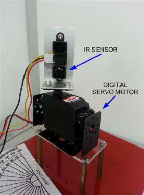
There are four IR sensors used in this project. This type of sensor is chosen because of its lightweight property, and they are mounted on the hardware platform to perform the necessary coordinate marking and diameter measurement operations. Two IR sensors are functioning as the X-Y coordinate marker during the navigation process, and the others are used in the diameter estimation operation. In this work, a GP2Y0A02YK0F IR sensor by Sharp Corporation is utilized. It is a type of proximity sensor, which is composed of an integrated combination of PSD (position sensitive detector), IRED (infrared emitting diode) and signals processing circuit. It also adopts the triangulation method in measuring the distance of the object which is not easily influenced by the variety of the reflectivity of the object, environmental temperature as well as the operating duration of the process. The chosen IR sensor is able to measure the distance of the object within the range of 20 cm to 150 cm with the supply voltage range of 4.5 t0 5.5 volts.
Two digital servomotors are used to cater the movement of the attached IR sensors in the XY-plane that is moving in the direction of -30° to +30°, similar to the movement of a car’s wiper. This movement is created so that the edge of the landmark could be detected and covered properly during the diameter estimation operation. The implemented digital servomotor is the HD-4180BB by professional servo R&D manufacturer, Power HD. A digital servomotor is chosen over the normal servo because the microcontroller to meet the requirement of the design can adjust the length of the input signals pulse or blip, and at the same time, the performance of it can be optimized. Secondly, the digital servomotor responds to the command from the microcontroller a little bit faster than the conventional servo motor. Therefore, it gives the servomotor an improved dead band, a quicker response, smoother acceleration or deceleration, better resolution and holding power. To energize the digital servomotor, an input of the pulse width modulation, PWM, which is generated by the microcontroller, is fed to the digital servo motor so that it moves towards the required direction, either counter clockwise or otherwise. In this research, the digital servomotor is programmed and controlled by the internal timer in the microcontroller. Fig. 7 shows the innovated
infrared scanner used in this work for diameter estimation process.
Fig. 7 Hardware setup for realizing the IR sensor scanner on the landmark surface for its diameter measurement
B. Software Development
There are few components developed in this area to support the overall operation of the proposed inter-row tree detection and tracking techniques based on SLAM in this work. To facilitate this, these components are formulated in the Windows environment through a multi-paradigm and high-level object-oriented programming language, namely, Microsoft Visual Basic.NET 2008, which is one of programming tool in Microsoft Visual Studio Package. A database, which is provided by Microsoft Excel is integrated with the GUI to save data from the experiments for further performance analysis which is depicted in Fig. 8.
Fig. 8 Microsoft Visual Studio and Microsoft Excel are integrated into developing a fully functional GUI in this work
Fig. 9 Graphical User Interface for Inter-row tree tracking and navigation based on SLAM technique for an autonomous vehicle in the agricultural field
III.RESULT AND DISCUSSION
The real-time inter-row tree detection and tracking techniques based on SLAM can be seen clearly in the GUI that has been developed in Fig. 10. According to this figure, the navigated path, which is marked in blue colour is obtained from the real-time navigation process based on Bezier curve implementation. Then, the obtained data is compared with the red line, which is the ideal path or planned path that the autonomous should pass through in the overall process. Overall, ten tests have been performed to acquire the tree detection and tracking data which are then translated into pixels information for 2D-map virtual map display. Simultaneously, the location of the landmark is computed and marked on the GUI so that the deviation between the mapped landmark and the ideal location of it can be vividly seen and computed. For every test, the start point of the autonomous vehicle is set to be at the same place in order to have a uniform error analysis. The first landmark is denoted as the origin to simplify the starting point in the constructed local map. In the plotting area of the GUI, the grid is drawn at every 100 pixels which are 50 cm in ratio with the real environment. Therefore, in total, 200 pixels or 2 grids are equivalent to 1 meter distance from one landmark to another. The error analysis for landmark mapping, diameter measurement, and navigated path are elaborated more in the next paragraph.
The highest mapping error is 14.1 cm diverts from the ideal landmark location which is obtained during Landmark #2 detection and tracking operations. Despite that, the least
error obtained for this operation is acquired in the Landmark #6 with the error value of 2.5 cm deviates from the original location. The differences are caused by the position and orientation of the autonomous at that certain moment when the diameter estimation process is taken place as well as due to the efficiency of the IR measurement. The error in the measurement can be affected by the deficient of the voltage level at the ADC port in the microcontroller. Therefore, the power source that supplies the microcontroller board must be periodically checked to make sure that sufficient power is given to the entire hardware development board. Furthermore, the mapped landmark is noticeable to be plotted in the direction where the autonomous vehicle is facing at that time of landmark observation.
Another important aspect of this work is the efficiency of the navigation scheme in overall which has been outlined by using Bezier curve implementation for both straight navigation and headland turning operations. The highest navigation error is 11.5 cm which is obtained in the Fifth experiment and contrarily low in the Third experiment with the deviation error of 1.4 cm. The highest deviation is spotted obviously when the autonomous vehicle is extremely drifted away from its path during the headland turning operation because it will impact the rest of the navigation as more time and distance needed to bring back the vehicle on its path with the help of the landmark. However, when the autonomous is in the straight navigation mode, the error seems to be reduced as the vehicle position is controlled by the position of the landmarks before proceeding its trajectory to the next waypoint.
The overall average errors for diameter measurement, navigation, and landmark mapping are depicted in Table 1. The average error for diameter measurement, navigation, and landmark mapping is 0.61 cm, 4.0 cm, and 8.9 cm, respectively. For diameter measurement, compared with the result obtained in Table 1, the result of full implementation in 2D map construction experiment is slightly higher. This is due to several poles, which are in the same diameter, 9 cm, are used in the experiments, and the measurement is taken right after every navigation process which can indirectly affect the accuracy of the measurement. On the other hand, in this experiments, the combination of the straight navigation and headland turning in the overall implementation has given the average error of 4 cm deviation from its original path. Lastly, the mapping technique in this work has given the average error of 8.9 cm deviates from the original landmark location. However, this result is basically based on the laboratory environment to proof the concept of the proposed inter-row tree detection and navigation techniques based on SLAM. Please be noted that the result may differ from the real environment testing and implementation as the real landmarks are more challenging than the artificial landmarks.
TABLEI
RESULT OBTAINED FROM THE PROPOSED INTER-ROW TREE DETECTION AND TRACKING TECHNIQUES
Diameter
Measurement Navigation
Landmark Mapping Average
Error (cm)
Fig. 10 A GUI shows the resuJlt obtained from the real-time inter-row tree detection and tracking based on SLAM technique for agriculture application
For the localization of the autonomous vehicle in this tested environment, the present location of the vehicle is kept in the memory allocated in the microcontroller-based platform in terms of row and column as these data hold the total vertically and horizontally distances of the unmanned vehicle with the start point. Unfortunately, with this method, as the heading sensor is not used, the heading of the autonomous vehicle is determined by the number of the row. If the row numbers are ascending, the unmanned vehicle is moving to the north or upper of the area, otherwise, the vehicle is moving to the other way.
IV.CONCLUSION
This paper has presented the test conducted for real-time embedded tree detection and tracking based on SLAM for the lightweight unmanned vehicle. The tree detection, straight navigation, and headland turning schemes are tested for their hardware functionality in a real-time implementation. Even though this work is emphasized for lightweight hardware and inexpensive computation, it is proven that the implemented schemes are at the same pace and comparable with other approaches in real-time. A comprehensive application is outlined through a simplified GUI to demonstrate the functionality and effectiveness of these schemes to provide the automation needs in the agricultural sector specifically in the row-planted agriculture environment with small-scale unmanned aerial implementation. However, for future, this experiment can be carried for the relevant crash and non-crash scenarios for robustness and reliability testing.
ACKNOWLEDGMENT
This research is sponsored by Research Incentive Faculty (RIF) Fund, Universiti Teknologi MARA (Contract number: 600-RMI/DANA 5/3/LESTARI (70/2015)). We thank the
Research Management Institute (RMI), UiTM, FKE and Kalumpang, Hulu Selangor Agriculture Department for their support in terms of financial and knowledge.
REFERENCES
[1] G.-Q. Jiang, C.-J. Zhao and Y.-S. Si. (2010).A Machine Based Crop Rows Detection for Agricultural Robots, 2010 International Conference on Wavelet Analysis and Pattern Recognition, Qingdao, China.
[2] H. W. Griepentrog, A. Ruckelshausen, N. JØrgensen and I. Lund. (2010). Autonomous Systems for Plant Protection, Journal of Biomedical & Life Sciences, Precision Crop Protection – The Challenge and Use of Heterogeneity 2010, 323 - 334.
[3] J. Jutila, K. Kannas and A. Visala. (2007). Tree Measurement In Forest by 2D Laser Scanning, IEEE International Symposium on Computational Intelligence in Robotics and Automation, Jacksonville, FL, USA.
[4] M. Asif, S. Amir, A. Israr and M. Faraz. (2010). A Vision System for Autonomous Weed Detection Robot, International Journal of Computer and Electrical Engineering, 2(3), 486 – 491.
[5] M. Kise, Q. Zhang and F. R. Mas. (2005). A Stereovision-based Crop Row Detection Method for Tractor-automated Guidance, Biosystems Engineering, 90(4), 357 - 367.
[6] M. Miettinen, J. Kulovesi, J. Kalmari and A. Visala. (2010). New Measurement Concept for Forest Harvester Head, Field and Service Robotics Springer Tracts in Advanced Robotics, 62, 35-44. [7] M. Ohman, M. Miettinen, K. Kannas, J. Jutila, A. Visala and P.
Forsman. (2008), Tree Measurement and Simultaneous Localization and Mapping System for Forest Harvester, Field and Service Robotics Springer Tracts in Advanced Robotics, 42, 369-378. [8] M. Song, F. Sun and K. Iagnemma. (2012). Natural landmark
extraction in cluttered forested environments, IEEE International Conference on Robotics and Automation (ICRA), Saint Paul, MN. [9] M. Wang, H. Tamimi and A. Zell. (2005). Robot Navigation Using
Biosonar for Natural Landmark Tracking, IEEE International Symposium on Computational Intelligence in Robotics and Automation, Espoo, Finland.
[10] Norashikin M. Thamrin, Nor Hashim Mohd. Arshad, Ramli Adnan, Rosidah Sam, Noorfadzli A. Razak Mohamad Farid Misnan and Siti Fatimah Mahmud. (2013). A Low-Cost Rotational Infrared Scanner for Cylindrical Object Diameter Measurement, 2013 IEEE International Conference on Control System, Computing and Engineering, 29 Nov. - 1 Dec. 2013, Penang, Malaysia, 2013, 616-620.
[11] Q. Zhang, J. F. Reid and N. Noguchi.(1999). Agricultural Vehicle Navigation Using Multiple Guidance Sensors, International Conference on Field and Service Robotics.
[12] S. D. Kim, J. Katupitiya, R. Eaton and M. K. Ngai. (2009). Modeling and Control of the GreenWeeder for Crop Row Tracking, International Conference on Advance Robotics (ICAR 2009), Sydney, Australia.
[13] S. Ericson and B. Astrand. (2010). Row-detection On an Agricultural Field Using Omnidirectional Camera, 2010 IEEE/RSJ International Conference on Intelligent Robots and Systems, Taipei, Taiwan. [14] S. Hansen, E. Bayramoglu, J. C. Andersen, O. Ravn, N. Andersen
and N. . K. Poulsen. (2011). Orchard navigation Using Derivative Free Kalman Filtering, 2011 American Control Conference, San Francisco, California, USA.
[15] V. Subramaniam, T. F. Burks and A. A. Arroyyo. (2006). Development of Machine Vision and Laser Radar based Autonomous Vehicle Guidance System for Citrus Grove Navigation, Journal of Computers and Electronics in Agriculture, 53(2006/9), 130 - 143. [16] X. Jinlin and J. Weiping. (2010). Vision-based Guidance Line