+
JAST, Vol. 11, © Iranian Aeros
C
Cylindrical
industries, i
oil and gas.
structures ov
stiffness and
tailored by s
significant w
materials m
in the
designingcy
the load be
generally co
axial compr
1. Associate P 2. Assistant Pr 3. M. Sc.
No. 2, pp. 43-5 space Society, Su
Optim
Cylind
1, 2,
Comp structures of compo paper foc cylindrica ring-strin considere Optimizat stiffeners Rayleigh-3-D Finit that takes Rayleigh-methodol algorithm stiffened results sh stiffened c KeywordsIntrod
shells are w
including aer
One of the m
ver the conve
d strength of
selecting orie
weight redu
makes compos
design of
ylindrical she
aring aspects
onstrained w
ression. Ther
Professor rofessor (Corres 51 mmer-Fall 2017
mizati
drical
M. Fako
3. Faculty of
posite stiffened s. In the recent osite stiffened c cuses upon the al shell. The op nger stiffened c ed as design co
tion (PSO) alg is considered -Ritz energy me te Element (FE s into considera -Ritz energy me logy is impleme m. The obtained cylindrical she how that the pr cylindrical shel
s: Optimization, P
duction
123widely used
rospace, mar
main advantag
entional struc
f composite s
entation of fib
ction offered
sites a more
cylindrica
lls with a m
s of these st
with a loss of
refore, the bu
sponding Autho
ion of
Shell
oor
1, P. Mo
f New Scienc
Postal code
mfa
cylindrical she years, there ha cylindrical she e development ptimization prob composite cylin
onstraints. The gorithm. The m d to be isotrop ethod and the st EM) model of th ation the exact g ethod are comp ented on the r d results show ell whilst all t roposed method ll design proble
PSO algorithm, C
in a variety
rine, automot
ges of compo
ctures is that
structures can
bers. In addit
d by compo
attractive opt
al shells.
minimum wei
tructures will
f stability un
uckling load
our)
f Com
l using
ohammadza
ce and Techn
e: 3456746, T
[email protected]
ells are widely as been a grow ell structures fo of an efficient blem used in th ndrical shell wi e proposed met material of sh pic. The appro tiffeners are tre he ring-stringer geometric confi pared with tho ing-stringer stif w a 13% reduc
the design con dology provides ems.
Cylindrical shell, C
y of
tive,
osite
the
n be
tion,
osite
tion
In
ight,
l be
nder
and
the
con
des
add
num
me
des
tim
com
alg
bee
the
his
stru
res
pre
rev
app
mposit
g PSO
ade
2*and E
nologies, Un
Tehran, Iran
ac.ir
used as primar wing research in or stability und t optimization o is study involve ith buckling loa thodology is b hell is compos oach adopted eated as discrete
r stiffened cylin figuration. The r ose using 3-D F
iffened cylindri ction in the we nstraints are sa
s an effective w
Composites
e weight of
nsiderations
sign flexibili
ditional desig
mber and l
echanical beh
sign of comp
me consumi
mposites hav
gorithms in th
en the focus o
e past two dec
A survey p
storical revie
uctures and a
spect to ind
esented in [
view of pr
plications
te Stiff
O Algo
E. Jafari
3niversity of T
ry elements in nterest in optim der buckling lo
of ring-stringer es weight minim ad and stress,
ased on Partic ite, but the m in modeling u e members. In a ndrical shell is results obtained FE model. The ical shell using eight of the rin atisfied. In add way of solving
f structures
in their desi
ity offered b
gn variables
layer thickn
havior of su
posite structu
ing process
ve motivated
he design of s
of many rese
cades [2-5].
paper by Ga
ew of optim
a study of co
dustrial app
[7]. Bruynee
roblems, so
of optimi
ffened
orithm
Tehran
aerospace mum design oad. Thisr stiffened mization of which are cle Swarm material of utilizes the addition, a developed d using the e proposed g the PSO ng-stringer dition, the
composite
are two m
ign [1]. In a
by composite
s (e.g., fiber
ness) and th
uch material
ures a more
s. These
d the use of
such structure
earch program
anguli [6] has
mal design o
44
/
Journal of Aerospace Science and TechnologyVol. 11/ No. 2/ Summer-Fall 2017 F. Fakoor, P. Mohammadzadeh and E. Jafari
composite structures. In the recent years, there has
been significant progress in the application of
optimization on composite cylindrical shells [9-12].
Many researchers attempted to employ Genetic
Algorithm (GA) in the optimization of composite
structures [13-16]. Park et al. [17] have presented
optimization of composite laminate stacking sequence
by considering the uniform tensile axial loads to
enhance strength using the theory of first-order
transverse shear deformation based on Genetic
Algorithm (GA). Gharib and Shakeri [18] have
presented optimization of the stacking sequence of a
laminated cylindrical shell with natural frequency and
buckling load as the objective functions using GA
and artificial neural networks (NN). Sadiqfar et al.
[19] introduced GA in multi-objective optimization of
stiffened cylindrical shells to achieve the minimum
weight and maximum axial buckling load. Talebi et
al. [20] proposed a novel tank design algorithm using
GA for enhancing roll stability of fuel tank shape
considering the multi-objective optimization of the
problem. The main drawbacks of the use of GA in
optimization ofcomposite structures is a high number
of evaluations required and the corresponding high
computational time.
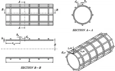
Fig. 1 Geometry of stiffened cylindrical shell
Particle swarm optimization (PSO) is a
meta-heuristic
optimization
algorithm
that
is
computationally more efficient than GA. This
algorithm is an evolutionary algorithm introduced by
Kennedy and Eberhart [21] and is inspired by the
social behavior of animals such as fish and birds that
live together in small and large groups.The fast
convergence rate, the ease of implementation and the
number of parameters set are other advantages of
PSO [22-23]. Suresh et al. [24] has employed PSO as
a multi-agent search method to maximize elastic
coupling of a composite helicopter rotor blade. Chang
et al. [25] introduced a method based on PSO for
stacking sequence design. Some researchers used
PSO algorithm in the optimization problem of
composite cylindrical shells.
This paper focuses on the optimization of
composite stiffened cylindrical shell. The methodology
presented in this paper involves the minimization of the
weight of the stiffened cylindrical shell subjected to
buckling and stress constraints as well as the side
constraints of the design variables. The main
motivations and contributions of this paper are: (I)
development of an efficient optimization algorithm
using PSO for optimum design of composite stiffened
cylindrical shell, (II) comparative study of
computational performance of GA and PSO on the
composite stiffened cylindrical shell, (III) study ofthe
effect of number of ring and stringer on buckling
load, (IV) study of effect of
⁄
on buckling load.
(1)
= ( , ) + ( , )
= ( , ) + ( , )
= ( , )
Composite stiffened cylindrical shell
equations
Consider a homogeneous circular cylindrical shell with thickness ℎ, length , mean radius , mass density , modulus of elasticity , Poisson’s ratio and shear modulus = /2(1 + ). The shell is reinforced by rings of equal or unequal spacing and stringers of equal spacing. A coordinate system
( , , ) is fixed on the middle surface of the shell at one of its two ends,height of the stringer and the ring are shown with dand d , respectively, and the widths correspond to b and b . The intervals of the mid-shell to the geometric center of the stringer and the ring are marked with the zand zsymbols, respectively.As shown in Fig. 1., the displacements of the different points of the shell are related to the displacements of mid surfaces by the Eq. 1. Where( , , ) are the orthogonal components of displacement of an arbitrary point ( , , ) in the shell along the coordinates( , , ),
respectively, and ( , , ) are theinitial displacements of the shell mid-surface at point( , , ). Shell strain energy could be stated as follows:
(2)
= [ ]
Where[S] is the stiffness matrixand is mean radius.The strain vector, ε can be written as:
(3)
= { }
(4)
= , ; = , + ;
= , + ,
= − , ; = , − ,
/
45
Journal of Aerospace Science and Technology Vol. 11/ No. 2/ Summer - Fall 2017Optimozation of Composite Stiffened Cylindrical Shell Using PSO Algoritm
Where ε ،εθ ،γ θ are the mean surface strains which are defined with the curvature of the middle surface k ،kθ ،k θ in Equation 4.
According to the Love’s first approximation:
To obtain the stiffened equations, the
displacement according to the Euler-Bernoulli
theory in the directions
x,
θ
, z
are defined as
follows:
(6)
= −
The strain in axial direction is stated as:
The strain in circumferential direction is stated as:
(7) ε = ( − + w )
And the strain energy of the rings is [26-27]:
(8)
= ∑
+ ∑ π
, ,
,
,
are torsional rigidity,polar
moment of inertia, cross-section, elastic modulus
and the number of rings, respectively.
The strain energy of the stringers is [28]:
(9)
U = ∑
E
ε A dx
+ ∑
G J
dx
, ,
,
,
are torsional rigidity, polar
moment of inertia, cross-section, elastic modulus,
and the number of stringer, respectively.
Potential energy due to external forces including
internal and external axial pressure are stated as
follows:
Axial load [29]:
(10)
= − + +
is axial loading.
Potential energy due toinner pressure [29]:
(11)
= − +
There fore, potential energy function could be written as follows:
(12)
= + + + +
Where is shell strain energy, is strain
energy of the rings, is strain energy of the stringers,
is potential energy due to external forces and
is potential energy due toinner pressure.
Using the principle of minimum potential
energy and Ritz method (minimizing the energy
function relative to the Ritz function’s coefficients),
equilibrium equations can be obtainedas follows:
(13)
= 0 ⇒
= 0 = 0 = 0
To determine buckling load of the shell, Eq.13
can be rewritten as follows:
(14)
= 0
For Eq. 14 to have an unequivocal answer, the
determinant of equation 15 must be zeroed:
(15)
= 0
The elements of the determinant are stated in
Appendix (5).To calculate yield stresses, at first,
the values of A, B and C are obtained by Eq.
14,then, by replacing the revalues into Eq.s1 and 5,
the displacement field will be achieved. After
obtaining the displacements, by using Eq. 1, strains
and curvature will be obtained. Employing Hooke’s
relation for orthotropic materials, the stresses are
obtained for each laminate as follows:
(16)
= +
Eq.16 can be used for any point of the shell. Strain equations are employed to calculate stress in rings and stringers as follows:
(17)
= ( − + )
(18)
= ( − )
Analysis of Composite Cylindrical
Shell Using ANSYS
The modeling of composite cylindrical shell using
ANSYS software is performed for validation of the
the theoretical analysis. SHELL99 Linear Layered
Structural Shell has been chosen. The boundary
condition of simply supported is also selected as
follows:
(19)
= = = = 0 = 0
The shell structure is considered as a composite
material with the following properties (Table1).
(5)
( , ) = ( ) ( )
( , ) = ( ) ( ) = ( , ) = ( ) ( )
46
/
Journal of Aerospace Science and TechnologyVol. 11/ No. 2/ Summer-Fall 2017 F. Fakoor, P. Mohammadzadeh and E. Jafari
Table 1. Mechanical properties of cylindrical shell
Value Input parameters
144 [mm] 82.5 [mm]
146 9
10.8 9
5.78 9
0.29
0.04,0.06,0.14,0.26 [mm] ℎ
42,40,86,25 [ ]
The distances of the rings and stringers were
considered equal. The ring and stringer are made of
aluminum. The specification of rings and stringers
Table 2. Mechanical properties of stiffeners
Value
Input parameters
2
4 1 =
2.5
=
Comparison of Analytical and
Numerical Results
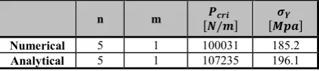
Table 3. Comparative results for verification of analytical results (no stiffened)
[ ]
[ / ]
m
n
185.2 100031 1 5
Numerical
196.1 107235 1 5
Analytical
Table 3 contains the comparison of analytical
and numerical results.
As shown in Table 3, the numerical results
extracted from ANSYS software approximately
coincide with the analytical results with only 5 to 6
percent error for the non-stiffened cylindrical shell.
Table4 includes the same results as Table 3 for
stiffened structure.
Table 4. Comparative results for Verification of analytical results (Stiffened)
As is listed in Table 4, the results of ANSYS
software matches with an error of 5.9 to 7 percent
in the analytical results of the stiffened cylinder.
In the presented method, the order of the reported values is negligible considering the engineering works. In the case of stiffened shells, the above approach could be applicable.
In order to analyze the shell stress and obtain the amount of yield stress, instead of the single pressure, a desired axial force in circumferential direction on the shell structure was applied, after obtaining the buckling load, the amount of yield stress for calculated buckling load can be determined
The Effect of Some Parameters on
Buckling Load
With MATLAB software, the effect of the number of
rings and stringers on buckling load were examined,
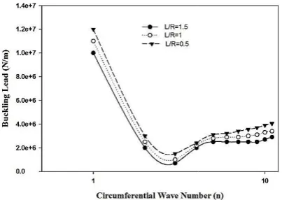
the corresponding diagram is shown in Fig.2.
From Fig. 2 it can be concluded that at small
circumferential wave number (i.e n = 1,2) the
influences of number of rings and stringers are
insignificant. Also, at large number of
circumferential waves,the buckling load increases
with number of rings and stringers. The unstiffened
shell has the lowest critical load in n=6 and m=1,
and in ouranalytical procedure, buckling occurred in
the same wave. Therefore, as the number of stringers
increases, buckling will occur in a higher load.
By passing from the half wave of 1 to 10, at
first,the buckling loads are decreases and
then,theywill increase. As shown in Appendix A, in
the buckling equation, sinus is also involved, due to
the periodic state of sinus function, the same
situation has happened for buckling loads. The
increase in the number of rings has a greater effect
on buckling load in comparison with the increase in
the number of stringers.
The effects of Length to cylinder radius ratio arealso shown in Fig. 3.
Figure 2. Effect of number of ring and stringer on buckling load.
[ ]
[ / ]
m
n
159.6 135041 5 13
Numerical
171.7 143523 5 13
Analytical
Optimozation of Composite Stiffened Cylindrical Shell Using PSO Algoritm
Figure 3. Effect of ⁄ on buckling load
It can be found that bythe increase
the mean radiusratio, the critical load of the
stiffened cylindrical shell decreases; this trend is
proportional to the ratio of thickness to radius, as
the thickness of shell increases, the buckling occurs
in higher loads.
Particle Swarm Optimization
PSO algorithm is inspired by the behavior of a group of birds, fish or insects in search of food or a certain way Each particle expresses its position and speed using its memories and other particles, the basic steps in the PS algorithm are as follows:
1.Generate the population of primary particles with random position values and initial random velocity. 2.Determine the new velocity vector for each particle of
the population using the best previous position of each particle up to that moment, the best position experienced in the total particle population, and also the velocity vector of each particle before each other. 3.Change and improve the current position of each
particle using the velocity vector of the previous position of each particle.
4.Repeat from step 2 until the desired stop criteria
The vector of the velocity and position of each
particle can be expressed by the following Equations:
= + −
+ −
= +
In these equations, i represents a particle, and the index k represents the number of repetitions, V represents the velocity, and X represents the position,
random numbers with uniform distribution in the interval {0, 1}. The coefficients and
acceleration constants. W is the coefficient of inertia. is the best experienced by the particle up to that moment, is the best experienced situation in the whole population that is repeated.
Journal of Aerospace Sc Vol. 11/ No. 2/ Summer -Optimozation of Composite Stiffened Cylindrical Shell Using PSO Algoritm
buckling load.
increase in length to
ratio, the critical load of the
stiffened cylindrical shell decreases; this trend is
proportional to the ratio of thickness to radius, as
es, the buckling occurs
Optimization (PSO)
inspired by the behavior of a group ofsearch of food or a certain way. Each particle expresses its position and speed using its d other particles, the basic steps in the PSO Generate the population of primary particles with random position values and initial random velocity. Determine the new velocity vector for each particle of the population using the best previous position of each that moment, the best position experienced in the total particle population, and also the velocity vector of each particle before each other. Change and improve the current position of each particle using the velocity vector of the previous
until the desired stop criteria.
The vector of the velocity and position of each
particle can be expressed by the following Equations:
(20)
(21) represents a particle, and the index represents the number of repetitions, V represents the velocity, and X represents the position, and and are random numbers with uniform distribution in the and are particle is the coefficient of is the best experienced by the particle up he best experienced that is repeated.
Formulation of optimization problem
This section describes formulation of the optimization of the ring-stringer composite stiffened cylindrical shell. The optimization problem involves minimization of the weight of the ring-stringer composite stiffened cylindrical shell. The constraints of the problem are buckling load and stress as well as the side constraints of the design variables. The design variables and constraints are shown in Tablesthe optimization problem can be written as: Minimize an objective function
Subject to constraint:
( ) ( ) = 1, … , = 1, … , is variable parameter and
is upper limitation as defined in Table
( ) = −
Where
is buckling loadthat is derived
by equation 20 and is a function of variable
parameters.
( ) =
Where
is maximum yield stress of
structure that is derived by equation
function of variable parameters.The most straight
forward technique to take constraints into account is
the incorporation of penalty functions to the objective
function. To get faster results and better control of the
optimization process, some scale factors of the
function have to be introduced to minimize (f). The
objective function would be as follows:
( ) = ( ) + ( ((
Where 0.
Table 5. Design Variable Parameter
Upper limitation Design variable Notation
1.2 ℎ ( = 1,2,3) , ,
10 8
8 10
8
8
6500 0.35 90 ( = 1,2,3)
, ,
15 450 200 0.3 40
/
47
Journal of Aerospace Science and Technology- Fall 2017
of optimization problem
This section describes formulation of the optimization of stringer composite stiffened cylindrical shell. problem involves minimization of the stringer composite stiffened cylindrical shell. The constraints of the problem are buckling load and stress as well as the side constraints of the design variables. The design variables and ts are shown in Tables 5 and 6. Formulation of the optimization problem can be written as:Minimize an objective function ( ) =
is lower limitation and is upper limitation as defined in Table 5.
is buckling loadthat is derived
and is a function of variable
is maximum yield stress of
hat is derived by equation 22 and is a
function of variable parameters.The most
straight-forward technique to take constraints into account is
the incorporation of penalty functions to the objective
function. To get faster results and better control of the
optimization process, some scale factors of the
function have to be introduced to minimize (f). The
objective function would be as follows:
( ) ( ) − 1,0
Design Variable Parameter
Unit Lower limitation Upper limitation
[mm] 0.5 1.2
[mm] 1 10
[mm] 2 8
[mm] 2
8
[mm] 1
10
[mm] 2 8
[mm] 2
8
[ / ]
2000 6500
0.15 0.35
[Deg] 0
90
[ ]
2 15
[ ]
80 450
[ ]
50 200
[ ]
0.25 0.3
[ ]
48
/
Journal of Aerospace Science and Technology Vol. 11/ No. 2/ Summer-Fall 2017Objective function
As indicated in the previous section, the objective function is the minimization of the total weight of the ring-stringer composite stiffened cylindrical shell ( which can be expressed as follows:
The objective function of this research is the
mass, or the weight of the cylindrical shell. Total
mass is a function of the mass of the shell, plus the
mass of the mounted stiffeners.
= + +
Is the total weight and and are the weight the rings and stringers, respectively.
The weight of the cylindrical shell is obtained from Eq.23:
= ∑ = {( − )}
= (0.165 + + ) + (0
+ ) + (0.165 − − )]
= 0.165 . ( + + )
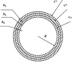
Where is the radius of nth composite laminate. of laminates (see Fig. 4) areassumed in the test problem of this paper. Hence, there are:r , ,
composite density.
Figure 4. Cylindrical shell (3 laminates) Rings weight(Fig. 1):
= . = 2 +
= 2 . . . + . . =
2 . . . 0.0825 + .
N is the number of rings, dis the height of the ri
b is the width of the rings, ρ is the density of the ri and t is the thickness of the shell.
Stringer’s weight isas follows:
= =
= 0.144( . . . )
N is the number of stringers, dis the height of the stringers, b is the width, andρ is the density of the stringers
Journal of Aerospace Science and Technology F. Fakoor, P. Mohammadzadeh and E. Jafari
As indicated in the previous section, the objective of the total weight of the stringer composite stiffened cylindrical shell ( ),
function of this research is the
mass, or the weight of the cylindrical shell. Total
the shell, plus the
(22)
are the weights of is obtained from
(23)
(0.165 −
composite laminate. 3layers n the test problem
, , and ρ is the
laminates).
(24)
.
is the height of the rings, is the density of the rings
(25)
is the height of the is the density of the stringers.
Finally, the objective function is as follows
= 0.165 . . ( + 2 . . . 0.0825 +
. . + 0.144
Constant design parameters
Table6. The design variables includes: properties of
the composite material
properties
of
the
stiffener
(
,
,
)
, number of rings
of stringer , cross-section of rings
section of stringers
.
is presented in Table 5.
Table 6. Constant Design Parameter
Input parameters Length of shell (L) Radius of shell Number of laminates
Axial load( Na) Inner pressure (P)
Yield Stress( )
Design Constraints
The design constraints of the test problem are buckling load and yield stress as shown in Table
load is 1, and no dimensional constraint buckling means that buckling load of stiffened cylindrical shell (F ) that is obtained with the developed MATLAB code, should be greater than the allowed load F , otherwise, the stiffened cylindrical shell will be buckled.
The Yield stress is
constraint Yield stress means that stiffened cylindrical shell ( the developed MATLAB code the allowable stress
cylindrical shell will reach to yield point.
Table 7. Design constraints
− 1 0
Buckling Constraint
− 1 0
Yield Stress Constraint
Results
Fig. 5 shows the convergence diagram of weighting function to the number of generation based on genetic algorithms.
P. Mohammadzadeh and E. Jafari
the objective function is as follows:
(26)
+ ) +
144( . . . )
Constant design parameters arepresented in
The design variables includes: properties of
the composite material
( ,
,
,
)
,
the
stiffener’s
material
, number of rings , number
section of rings
,
cross-. the range of limitation
Constant Design Parameter
Value 144 [mm] 82.5 [mm]
3 1.5e7 [N/m]
20 [KPa]
210 [MPa]
The design constraints of the test problem are buckling load and yield stress as shown in Table 7.The buckling no dimensional constraint buckling means that buckling load of stiffened that is obtained with the developed MATLAB code, should be greater than the , otherwise, the stiffened cylindrical shell will be buckled.
1, and no dimensional constraint Yield stress means that the maximum stress of
) that is obtained with the developed MATLAB code, should be smaller than , otherwise, the stiffened l shell will reach to yield point.
Design constraints
= 1.5 7
is calculated by
code in matlab
= 210 6
is calculated by
code in matl
Results
/
49
Journal of Aerospace Science and Technology Vol. 11/ No. 2/ Summer - Fall 2017Optimozation of Composite Stiffened Cylindrical Shell Using PSO Algoritm
Due to the large difference between the scale
of variable parameters (as mentioned some of them
are on the scale of millimeters and some on the
Giga scale), the range of all variables was set
between {1, 11} and then, after obtaining the final
answer of 17.776, the final values of all variable
parameters that are between 1 and 11, were
returned by Eq.26 to the initial scale.
For example, if the range of variables are between L and U and the obtained value from the optimization procedure is S, the final value of the parameter can be obtained as follows:
(27)
=( − )10 ∗ ( − 1) +
After making this scale conversion for all
parameters, the final and optimized values of the
variables are obtained.By obtaining variables, the
amount of shell weight that is the objectivefunction
in its original range can be calculated; after this
stage, the objective function 4.132 is obtained. The
optimum value of the particle swarm algorithm (see
Fig. 6) is also performed with the same scale
variation as was mentioned before. Finally, the
final weighting function was achieved as
4.1280,which weighed 13.2% relative to the initial
shell weighing 4.78.
After optimizing both the genetic algorithm
and the particle swarm, the optimized weight
decreased by 13.1% compared to the initial weight,
while it has not reached critical loads and has not
reached the yield stress (Table 8).
Figure 5. Convergence of weight to iteration (Genetic Algorithm)
Table 8. Result of optimization
Yield Stress [Mpa] Critical Load
[N/m] Error Results
[kg] Algorithim
206 13054403
3.128
PSO
207.3 14067323 0.12 3.132
GA
Figure 6. Convergence of weight to iteration (PSO Algorithm)
Final values of parameters arelistedinTable 9.
Table 9. Final value of variable parameters
Unit
Design variable Notation
[mm] 0.69,0.53,0.78
ℎ ( = 1,2,3) , ,
3
[mm] 4.1
[mm] 5.8
4
[mm] 2.1
[mm] 4.7
[ / ]
2604
0.29
[Deg] 35,42,38 ( = 1,2,3)
, ,
[ ]
5.9
[ ]
432
[ ]
182
0.29
[ ]
15
Conclusion
50
/
Journal of Aerospace Science and TechnologyVol. 11/ No. 2/ Summer-Fall 2017 F. Fakoor, P. Mohammadzadeh and E. Jafari
conditions were simply supported. Related constraints wereconsidered in m separatedMATLAB files and are called in each replication and checked by an algorithm in whichthe direction of the objective function in the region was acceptable. After optimizing both the genetic algorithm and the particle swarm, the optimized weight decreased by 13.1% compared to the initial weight, while it didnot reach critical buckling loads and didnot reach the yieldstress.Also, the final values of optimization by each genetic and particle accumulation werevery close, but the particle swarm approachwasmuch faster than the genetic method.
Appendix
= − − − + +
= + + + −
=
+ + + − + ( +
) =
= − − − − −
4 − − − ∑ ( ) −
= − − − − 2 −
− − − − ∑ ( )
− − ∑ ( )
=
=
= − − 2 − − − − − −
− − −
− + ∑ ( )
− ∑ (cos ) − ( + )
− ∑ ( ) −
References
[1]Simitses, G. J., “Buckling and Postbuckling of Imperfect Cylindrical Shells: A Review“, Applied Mechanics Reviews, Vol. 39, No. 10, pp. 1517-1524, 1986.
[2]Akbulut, M. and F. O. Sonmez (2008). "Optimum design of composite laminates for minimum thickness." Comput. Struct. 86(21-22): 1974-1982. [3]Lopez, R., et al. (2009). Optimization of laminated
composites considering different failure criteria. [4]Coburn, B. H., et al. (2014). "Buckling analysis of
stiffened variable angle tow panels." Composite Structures 111: 259-270.
[5]Ye, F., et al. (2017). "Variable stiffness composite material design by using support vector regression assisted efficient global optimization method."
Structural and Multidisciplinary Optimization 56(1): 203-219.
[6]Ganguli, R. (2013). Optimal Design of Composite Structures: A Historical Review.
[7]Bahubalendruni, M. V. A. R. and B. B. Biswal (2014). Study of optimization of composite structures with respect to industrial applications. 2014 IEEE 8th International Conference on Intelligent Systems and Control (ISCO).
[8]Henrichsen, S. R. (2015). Optimization of Laminated Composite Structures, Aalborg Universitetsforlag. [9]Koide, R. M. and M. A. Luersen (2013).
"Maximization of Fundamental Frequency of Laminated Composite Cylindrical Shells by Ant Colony Algorithm." Journal of Aerospace Technology and Management 5: 75-82.
[10]Léné, F., et al. (2009). "An advanced methodology for optimum design of a composite stiffened cylinder." Composite Structures 91(4): 392-397. [11]Muc, A., “Transverse shear effects in discrete
optimization of laminated compressed cylindrical shells“, Composite Structures, Vol. 38, No. 1, pp. 489-497, 1997/05/01, 1997.
[12]Paweł Foryś, Optimization of cylindrical shells stiffened by rings under external pressure including their post-buckling behaviour, Institute of Applied Mechanics, Cracow University of Technology, al. Jana Pawła II 17, 31-864 Kraków, Poland.
[13]Khong, P., “Optimal Design of Laminates for Maximum Buckling Resistance and Minimum Weight“, 1999.
[14]Walker, M., Smith, R. E., “A technique for the multiobjective optimisation of laminated composite structures using genetic algorithms and finite element analysis“, Composite Structures, Vol. 62, No. 1, pp. 123-128, 10//, 2003.
[15]Adams, D. B., Watson, L. T., Gürdal, Z., Anderson-Cook, C. M., “Genetic algorithm optimization and blending of composite laminates by locally reducing laminate thickness“, Advances in Engineering Software, Vol. 35, No. 1, pp. 35-43, 1//, 2004.
[16]MH Shojaeifard, R Talebitooti, A Yadollahi, Optimization of sound transmission through laminated composite cylindrical shells by using a genetic algorithm, mechanics of composites materials, September 2011, 47:481.
[17]Park, J. H., Hwang, J. H., Lee, C. S., Hwang, W., “Stacking sequence design of composite laminates for maximum strength using genetic algorithms“, Composite Structures, Vol. 52, No. 2, pp. 217-231, 5//, 2001
/
51
Journal of Aerospace Science and Technology Vol. 11/ No. 2/ Summer - Fall 2017Optimozation of Composite Stiffened Cylindrical Shell Using PSO Algoritm
[19]Sadeghifar, M., Bagheri, M., Jafari, A. A., “Multiobjective optimization of orthogonally stiffened cylindrical shells for minimum weight and maximum axial buckling load“, Thin-Walled Structures, Vol. 48, No. 12, pp. 979-988, 12//, 2010. [20]R. Talebitooti, MH Shojaeefard, S
Yarmohammadisatri, Shape design optimization of cylindrical tank using b-spline curve, Computers and Fluids, Vol 109, 10 March 2015, Pages 100-112. [21]Kennedy, J., Eberhart, R., “Particle swarm
optimization“, in Proceeding of, 1942-1948 vol.4. [22]P. Y. Jiang, Z. M. Lin, J. Xu, and J. Q. Sun, “A
Particle Swarm Optimization Algorithm for Minimizing Weight of the Composite Box Structure,” in Advanced Materials Research, 2012, vol. 430, pp. 470–475.
[23]I. C. Trelea, “The particle swarm optimization algorithm: convergence analysis and parameter selection,” Inf. Process. Lett., vol. 85, no. 6, pp. 317–325, 2003.
[24]S. Suresh, P. B. Sujit, and A. K. Rao, “Particle swarm optimization approach for multi-objective composite box-beam design,” Compos. Struct., vol. 81, no. 4, pp. 598–605, 2007.
[25]N. Chang, W. Wang, W. Yang, and J. Wang, “Ply stacking sequence optimization of composite laminate by permutation discrete particle swarm optimization,” Struct. Multidiscip. Optim., vol. 41, no. 2, pp. 179–187, 2010.
[26]Akl, W., Ruzzene, M., Baz, A., “Optimal design of underwater stiffened shells“, Structural and Multidisciplinary Optimization, Vol. 23, No. 4, pp. 297-310, 2002.
[27]Tian, J., Wang, C. M., Swaddiwudhipong, S., “Elastic buckling analysis of ring-stiffened cylindrical shells under general pressure loading via the Ritz method“, Thin-Walled Structures, Vol. 35, No. 1, pp. 1-24, 9//, 1999.
[28]Rinehart, S. A., Wang, J. T. S., “Vibration of simply supported cylindrical shells with longitudinal stiffeners“, Journal of Sound and Vibration, Vol. 24, No. 2, pp. 151-163, 1972/09/22, 1972.
[29]Lim, C., Ma, Y., “Computational p-element method on the effects of thickness and length on self-weight buckling of thin cylindrical shells via various shell theories“, Computational mechanics, Vol. 31, No. 5, pp. 400-408, 2003.