Volume 2, Issue 8, August 2013
Page 128
ABSTRACT
Space-time block codes have been shown to perform well with Multiple-Input Multiple Output (MIMO) systems. STBC is a MIMO transmit strategy which exploits transmit diversity and high reliability. Multiple-input multiple-output (MIMO) transmission scheme, called space-time block coded spatial modulation (STBC-SM), is proposed. It combines spatial modulation (SM) and space-time block coding (STBC) to take advantage of the benefits of both while avoiding their drawbacks. In the STBCSM scheme, the transmitted information symbols are expanded not only to the space and time domains but also to the spatial (antenna) domain which corresponds to the on/off status of the transmit antennas available at the space domain, and therefore both core STBC and antenna indices carry information. A general technique is presented for the design of the STBC-SM scheme for any number of transmits antennas besides the high spectral efficiency advantage provided by the antenna domain; the proposed scheme is also optimized by deriving its diversity and coding gains to exploit the diversity advantage of STBC. A low-complexity maximum likelihood (ML) decoder is given for the new scheme which profits from the orthogonality of the core STBC. The performance advantages of the STBC-SM over simple SM and over V-BLAST are shown by simulation results for various spectral efficiencies and are supported by the derivation of a closed form expression for the union bound on the bit error probability.
Keywords: Multiple-Input Multiple-Output (MIMO), Maximum likelihood decoding (ML), Space-time block codes/coding, spatial modulation
1. INTRODUCTION
MIMO technology means multiple antennas at both the ends of a communication system, that is, at the transmitting end and receiving end. The idea behind MIMO is that the transmit antennas at one end and the receive antennas at the other end are connected and combined in such a way that the bit error rate (BER), or the data rate for each user is improved .MIMO has the capacity of producing independent parallel channels and transmitting multipath data streams and thus meets the demand for high data rate wireless transmission. This system can provide high frequency spectral efficiency and is a promising approach with tremendous potential.The use of multiple antennas at both transmitter and receiver has been shown to be an effective way to improve capacity and reliability over those achievable with single antenna wireless systems. Consequently, multiple-input multiple-output (MIMO) transmission techniques have been comprehensively studied over the past decade by numerous researchers, and two general MIMO transmission strategies, a space-time block coding1 (STBC) and spatial multiplexing, have been proposed. The increasing demand for high data rates and, consequently, high spectral efficiencies has led to the development of spatial multiplexing systems such as V-BLAST (Vertical-Bell Lab Layered Space-Time).In V-BLAST systems, a high level of inter-channel interference (ICI) occurs at the receiver since all antennas transmit their own data streams at the same time. This further increases the complexity of an optimal decoder exponentially, while low-complexity sub optimum linear decoders, such as the minimum mean square error (MMSE) decoder, degrade the error performance of the system significantly. On the other hand, STBCs offer an excellent way to exploit the potential of MIMO systems because of their implementation simplicity as well as their low decoding complexity. A special class of STBCs, called orthogonal STBCs (OSTBCs), has attracted attention due to their single-symbol maximum likelihood (ML) receivers with linear decoding complexity. However it has been shown that the symbol rate of an OSTBC is upper bounded by ¾ symbols per channel use (PCU) for more than two transmit antennas. Several high rate STBCs have been proposed in the past decade, but their ML decoding complexity grows exponentially with the constellation size, which makes their implementation difficult and expensive for future wireless communication systems. Recently, a novel concept known as spatial modulation (SM) has been introduced by Mesleh etal. in and to remove the ICI completely between the transmit antennas of a MIMO link. The basic idea of SM is an extension of two dimensional signal constellations (such as -ary phase shift keying ( -PSK) and -ary quadrature amplitude modulation ( -QAM), where is the constellation size) to a third dimension, which is the spatial (antenna) dimension. Therefore, the information is conveyed not only by the amplitude/phase modulation (APM) techniques, but also by the antenna indices. An optimal ML decoder for the SM scheme, which makes an exhaustive search over the aforementioned three dimensional space has been presented in that the error performance of the SM scheme can be improved
Performance Analysis of MIMO using Space
Time Block Coded Spatial Domain
V.RamaKrishna1, P.SrinivasaRao2
1Dept of DECS, St Ann’s College of Engineering and Technology,
From JNTUK, affiliated to AICTE, Chirala.
2Asst.Professor, St Ann’s College of Engineering and Technology,
Volume 2, Issue 8, August 2013
Page 129
approximately in the amount of 4 dB by the use of the optimal detector under conventional channel assumptions and that SM provides better error performance than V-BLAST and maximal ratio combining (MRC).More recently, Jeganathan etal. Have introduced a so-called space shift keying (SSK) modulation scheme for MIMO channels in . In SSK modulation, APM is eliminated and only antenna indices are used to transmit information, to obtain further simplification in system design and reduction in decoding complexity. However, SSK modulation does not provide any performance advantage compared to SM. In both of the SM and SSK modulation systems, only one transmit antenna is active during each transmission interval, and therefore ICI is totally eliminated. where different combinations of the transmit antenna indices are used to convey information for further design flexibility. Both the SM and SSK modulation systems have been concerned with exploiting the multiplexing gain of multiple transmit antennas, but the potential for transmit diversity of MIMO systems is not exploited by these two systems. This leads to the introduction here of Space Time Block Coded Spatial Modulation (STBCSM), designed to take advantage of both SM and STBC. An STBC is usually represented by a matrix. Each row represents a time slot and each column represents one antenna's transmissions over time.Here, is the modulated symbol to be transmitted in time slot from antenna . There are to be time slots and transmit antennas as well as receive antennas. This block is usually considered to be of 'length' the code rate of an STBC measures how many symbols per time slot it transmits on average over the course of one block. If a block encodes symbols, the code-rate is
Only one standard STBC can achieve full-rate (rate 1) — Alamouti's code.
2. MULTIPLE INPUT MULTIPLE OUTPUT (MIMO)
MIMO system is commonly used in today's wireless technology, including 802.11n WiFi, WiMAX, LTE, etc. Multiple antennas (and therefore multiple RF chains) are put at both the transmitter and the receiver.
FIG. 1: BLOCK DIAGRAM OF MIMO
Volume 2, Issue 8, August 2013
Page 130
3. SPACE-TIME BLOCK CODED SPATIAL MODULATION (STBC-SM)
A new MIMO transmission scheme, called STBC-SM, is proposed, in which information is conveyed with an STBC matrix that is transmitted from combinations of the transmit antennas of the corresponding MIMO system. The Alamouti code [3] is chosen as the target STBC to exploit. As a source of information, we consider not only the two complex information symbols embedded in Alamouti’s STBC, but also the indices (positions) of the two transmit antennas employed for the transmission of the Alamouti STBC. A general technique is presented for constructing the STBC-SM scheme for any number of transmits antennas. A low complexity ML decoder is derived for the proposed STBC-SM system, to decide on the transmitted symbols as well as on the indices of the two transmits antennas that are used in the STBC transmission. It is shown by computer simulations that the proposed STBC-SM scheme has significant performance advantages over the SM with an optimal decoder, due to its diversity advantage. A closed form expression for the union bound on the bit error probability of the STBCSM scheme is also derived to support our results. The derived upper bound is shown to become very tight with increasing signal-to-noise (SNR) ratio.
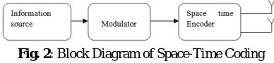
Fig. 2: Block Diagram of Space-Time Coding
In the STBC-SM scheme, both STBC symbols and the indices of the transmit antennas from which these symbols are transmitted, carry information. We choose Alamouti’s STBC, which transmits one symbol PCU, as the core STBC due to its advantages in terms of spectral efficiency and simplified ML detection. In Alamouti’s STBC, two complex information symbols ( 1 and 2) drawn from an -PSK or -QAM constellation are transmitted from two transmit antennas in two
symbol intervals in an orthogonal manner by the codeword.
X= X1 X2 =
X1 X2 → space
-X2∗ X1∗ ↓ time
Where columns and rows correspond to the transmit antennas and the symbol intervals, respectively. For the STBC SM scheme we extend the matrix in to the antenna domain.
4.
A
LAMOUTI’
SSTBC
Alamouti’s scheme was the first STBC that provides full diversity at full data rate for two transmit antennas. This scheme has full rate (i.e. a rate of 1) since it transmits two symbols every two time intervals. The information bits are first modulated using a digital modulation scheme, and then the encoder takes the block of two modulated symbols s1 and s2 in each encoding operation. Here we adopt multilevel modulation. First, we modulate m (m=log2 M) bits as a group, then the channel encoder will get two modulated signals s1, s2 as a group each time when encoding, and map the two signals into the transmit antennas. A simple Space Time Code, suggested by Mr. Siavash M Alamouti in his landmark October 1998 paper – A Simple Transmit Diversity Technique for Wireless Communication, offers a simple method for achieving spatial diversity with two transmit antennas. The scheme is as follows:
1. Consider that we have a transmission sequence, for example
2.In normal transmission, we will be sending in the first time slot, in the second time slot, and so on. 3. However, Alamouti suggested that we group the symbols into groups of two. In the first time slot, send and
from the first and second antenna In second time slot send and from the first and second antenna. In the third
time slot send and from the first and second antenna.In fourth time slot, send and from the first and second antenna and so on.
4. Notice that though we are grouping two symbols, we still need two time slots to send two symbols. Hence, there is no change in the data rate.
5. This forms the simple explanation of the transmission scheme with Alamouti Space Time Block coding.
Volume 2, Issue 8, August 2013
Page 131
Where , = 1, 2 are called the STBC-SM codebooks each containing two STBC-SM codeword’s X , = 1, 2 which do not interfere to each other. The resulting STBC-S code is =∪2 =1 . A non-interfering codeword group having elements is defined as a group of codeword’s satisfying X X = 02×2, , = 1, 2. . . , ∕= ; that is they have no overlapping columns. In (2), is a rotation angle to be optimized for a given modulation format to ensure maximum diversity and coding gain at the expense of expansion of the signal constellation. However, if is not considered, overlapping columns of codeword pairs from different codebooks would reduce the transmit diversity order to one. Assume now that we have four information bits ( 1, 2, 3, 4) to be transmitted in two consecutive symbol intervals by the STBCSM technique. The mapping rule for 2 bits/s/Hz transmission is given by Table I for the codebooks of (2) and for binary phase-shift keying (BPSK) modulation, where a realization of any codeword is called a transmission matrix. In Table I, the first two information bits ( 1, 2) are used to determine the antenna-pair position ℓ while the last two ( 3, 4) determine the BPSK symbol pair. If we generalize this system to - ary signaling, we have four different codeword’s each having 2 different realizations. Consequently, the spectral efficiency of the STBC-SM scheme for four transmit antennas becomes = (1/2) log24 2 = 1 + log2 bits/s/Hz, where the factor 1/2 normalizes for the two channel uses spanned by the matrices in.For STBCs using larger numbers of symbol. Intervals such as the quasi-orthogonal STBC for four transmit antennas which employs four symbol intervals, the spectral efficiency will be degraded substantially due to this normalization term since the number of bits carried by the antenna modulation (log2 ), (where is the total number of antenna combinations) is normalized by the number of channel uses of the corresponding STBC. A. STBC-SM System Design and Optimization In this subsection, we generalize the STBC-SM schemefor MIMO systems using Alamouti’s STBC to transmit antennas by giving a general design technique. An important design parameter for quasi-static Rayleigh fading channels isthe minimum coding gain distance (CGD) [15] between twoSTBC-SM codeword’s X and ˆX , where X is transmittedand ˆX is erroneously detected, is defined asNote that, min ( ) corresponds to the determinant criterion given in [14] since the minimum CGD between non
interfering codeword’s of the same codebook is always greater than or equal to the right hand side of (5). Unlike in the SM scheme, the number of transmit antennas in the STBC-SM scheme need not be an integer power of 2, since the pair wise combinations are chosen from available transmit antennas for STBC transmission. This provides design flexibility. However, the total number of codeword combinations considered should be an integer power of 2. In the following, we give an algorithm to design the STBC-SM scheme:
1) Given the total number of transmit antennas , calculate the number of possible antenna combinations for the transmission of Alamouti’s STBC, i.e., the total number of STBC-SM codeword’s from =( )⌋2, where is a positive
integer.
2) Calculate the number of codeword’s in each codebook
, = 1, 2, . .., −1 from = ⌊ /2⌋and the total number of codebooks from = ⌈ / ⌉. Note that the last codebook does not need to have codeword’s, i.e, its cardinality is ′ = − ( −1).
3) Start with the construction of 1 which contains no interfering codeword’s as
where X is defined in (1).
4) Using a similar approach, construct for 2 ≤ ≤ by considering the following two important facts: ∙ Every codebook
Volume 2, Issue 8, August 2013
Page 132
5) Determine the rotation angles for each , 2 ≤ ≤ , that maximize min ( ) in (5) for a givensignal constellation andantenna configuration; that is = arg max min ( ), where = ( 2, 3, . . , ).As long as the STBC-SM codeword’s
are generated bythe algorithm described above, the choice of other antennacombinations is also possible but this would not improve the overall system performance for uncorrelated channels Since we have antenna combinations, the resulting spectral efficiency of the STBC-SM scheme can be calculated as.
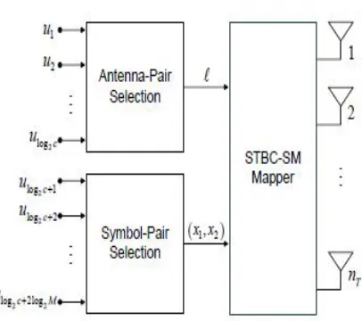
The block diagram of the STBC-SM transmitter is shown in fig
Fig. 3 Block diagram of the STBC-SM transmitter.
During each two consecutive symbol intervals, 2 bits = ( 1, 2, . . . , log2, log2+1, . . . , log2+2log2 ) enter the STBC-SM transmitter, where the first log2 bits determine the antenna-pair position ℓ = 12log2−1+ 22log2−2 + + log220
that is associated with the corresponding antenna pair, while the last 2log2 bits determine the symbol pair ( 1, 2) 2.
If we compare the spectral efficiency (7) of the STBC-SM scheme with that of Alamouti’s scheme (log2 bits/s/Hz), we
observe an increment of 1/2log2 bits/s/Hz provided by the antenna modulation. We consider two different cases for the
optimization of the STBC-SM scheme.
Case 1 - ≤ 4: We have, in this case, two codebooks 1
and 2 and only one non-zero angle, say , to be optimized. It can be seen that min ( 1, 2) is equal to the minimum CGD
between any two interfering code words from 1 and 2. Without loss of generality, assume that the interfering
Code words are chosen as
where X1 1 is transmitted and ˆX1 = X2 2 is erroneously detected. We calculate the minimum CGD between X1 and ˆX1 from (3) as min(X1 , ˆX1 )
Volume 2, Issue 8, August 2013
Page 133
Case 2 - > 4: In this case, the number of codebooks, , is greater than 2. Let the corresponding rotation angles to be optimized be denoted in ascending order by 1 = 0 < 2 < 3 < < < /2, where = 2 for BPSK and = 1 forQPSK. For BPSK and QPSK signaling, choosing
for 1 ≤ ≤ guarantees the maximization of the minimum CGD for the STBC-SM scheme. This can be explained as follows. For any , we have to maximize min ( ) as
where > , for > and the minimum CGD between codebooks and is directly determined by the difference between their rotation angles. This can be easily verified from
(9) by choosing the two interfering codeword’s as X and ˆX = X with the rotation angles and , respectively. Then, to maximize min ( ), it is sufficient to maximize the minimum CGD between the consecutive codebooks and +1, = 1, 2, . . ., −1. For QPSKsignaling, this is accomplished by dividing the interval [0, /2] into equal sub-intervals and choosing, for = 1, 2, . . . , −1,
+1 − = /2 The resulting maximum min ( ) can be evaluated from
Similar results are obtained for BPSK signaling except that /2 is replaced by / in (12) and (13). We obtain the corresponding maximum min ( ) as 2 ( 2) = 2 ( / ). On the other hand, for 16-QAM and 64-QAM signaling, the selection of { }’s in integer multiples of /2 would not guarantee to maximize the minimum CGD for the STBC-SM scheme since the behavior of the functions 16 ( ) and 64 ( )
Fig. 4. Variation of min ( ) given in (9) for BPSK, QPSK, 16-QAM and 64-QAM ( 2 ( ), 4 ( ), 16 ( ) and 64 ( )).
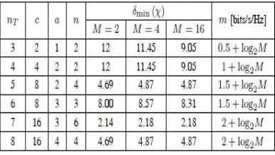
TABLE 1 Basic parameters of the STBC-SM system for different number of transmit antennas
Volume 2, Issue 8, August 2013
Page 134
signaling with > 6 as well as for 64-QAM signaling with > 2, the optimal { }’s must be determined by an exhaustive computer search. In Table II, we summarize the basic parameters of the STBC-SM system for 3 ≤ ≤ 8. We observe that increasing the number of transmit antennas results in an increasing number of antenna combinations and, consequently, increasing spectral efficiency achieved by the STBC-SM scheme. However, this requires a larger number of angles to be optimized and causes some reduction in the minimum CGD. On the other hand, when the same number of combinations can be supported by different numbers of transmit antennas, a higher number of transmit antennas requires fewer angles to be optimized resulting in higher minimum CGD (for an example, the cases = 8, = 5 and 6 in Table II). We now give two examples for the codebook generation process of the STBC-SM design algorithm, presented above. Design Example 1: From Table II, for = 6, we have = 8, = = 3 and the optimized angles are 2 = /3, 3 = 2 /3 for BPSK and 2 = /6, 3 = /3 for QPSK and 16-QAM. The maximum of min ( ) is calculated for BPSK, QPSK and 16-QAM constellations asAccording to the design algorithm, the codebooks can be constructed as below,
w( here 0 denotes the 2 × 1 all-zero vector. Since there are (6
2) = 15 possible antenna combinations, 7 of them are
discarded to obtain 8 codeword’s. Note that the choice of other combinations does not affect min ( ). In other words, the codebooks given above represent only one of the possible realizations of the STBC-SM scheme for six transmit antennas.
Design Example 2: From Table II, for = 8, we have = 16, = = 4 and optimized angles are 2 = /4, 3 =
/2, 4 = 3 /4 for BPSK and 2 = /8, 3 = /4, 4 = 3 /8 for QPSK and 16-QAM. Similarly, max min ( ) is calculated for BPSK, QPSK and 16-QAM constellations as
According to the design algorithm, the codebooks can be constructed as follows:
5.
O
PTIMALML
D
ECODER FOR THESTBC-SM
S
YSTEMIn this subsection, we formulate the ML decoder for the STBC-SM scheme. The system with transmit and receive antennas is considered in the presence of a quasi-static Rayleigh flat fading MIMO channel. The received 2 × signal matrix Y can be expressed as
Where X is the 2 × STBC-SM transmission matrix, transmitted over two channel uses and is a normalization factor to ensure that is the average SNR at each receive antenna. H and N denote the × channel matrix and 2 ×
Volume 2, Issue 8, August 2013
Page 135
(combination) ˆℓ and the information symbols ˆ 1 and ˆ 2. The block diagram of the ML decoder described above isgiven in Fig. 4
Fig. 5. Block diagram of the STBC-SM ML receiver.
In V-BLAST a single user's data stream is split into multiple sub-streams and we use an array of transmitter antennas to simultaneously launch the parallel sub-streams.All the sub-streams are transmitted in the same frequency band, so spectrum is used very efficiently. Since the user's data is being sent in parallel over multiple antennas, the effective transmission rate is increased in roughly in proportion to the number of transmit antennas used. In this system number of receivers is greater than number of transmitters. The transmitted sub-streams are independent of one another. Individual transmitter power is scaled by 1/M. So, total power remains constant independent of number of the transmitters (M).
6.
SIMULATION
RESULTS
We present simulation results for the STBCSM system with different numbers of transmit antennas and make comparisons with SM, V-BLAST, and STBC-SM.
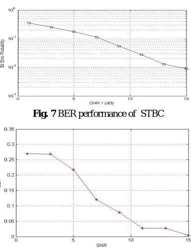
Fig. 6 BER performance of Alamouti STBC
Fig. 7 BER performance of STBC
Volume 2, Issue 8, August 2013
Page 136
Fig. 9 BER performance comparison of STBC,STBC-SM&VBLAST7. CONCLUSIONS
• We conclude that the STBC-SM scheme can be useful for high-rate, low complexity, emerging wireless communication systems such as LTE and WiMAX. Our future work will be focused on the integration of trellis coding into the proposed STBC-SM scheme.
• It was shown via computer simulations that the STBC-SM offers significant improvements in BER performance
compared to SM and V-BLAST systems with an acceptable linear increase in decoding complexity.
REFERENCES
[1] Mesleh, R., Haas, H., Sinanovic, S., Ahn, C.W. and Yun, S., 2008. Spatial Modulation, IEEE Trans. Veh. Technol., 57(4), 2228–2241.
[2] Basar, E., Aygölü, Ü., Panayırcı, E. and Poor, H.V., 2010. New Trellis Code¸ Design for Spatial Modulation, to
appear in IEEE Trans. on Wireless Commun.
[3] Mesleh, R., Renzo, M.D., Haas, H. and Grant, P.M., 2010. Trellis Coded Spatial Modulation, IEEE Trans. Wireless Commun., 9(7), 2349–2361.
[4] E.S. Hassan et.al,“Enhanced performance of OFDM and single-carrier systems using frequency domain equalization and phase modulation,” IEEE National Radio Science Conf., pp. 1-10, NewCairo, Egypt,2009.
[5] I. E. Telatar, “Capacity of multi antenna gaussian channels,” AT & T Bell Labs, Tech. Rep., Jun 1995
[6] G. J. Foschini & M.J. Gans, “On limits of wireless communications in a fading environment when using multiple antennas,” Wireless Personal Communication, vol.6, pp.311-335, March 1998.
[7] Proakis,JohnG; Digital Communication, Tata McGraw Hill, Fourth Edition.
[8] Yin Changchuan & Luo Tao. “Multi-carrier radio Communication Technology,” Posts and Telecommunications Press of Beijing University; 2004.
[9] M. J. Zhuang, “Performance analysis of multiple transmit antennas selection for the OSTBC MISO communication system,” Chinese Journal of Electronics, vol.15, pp. 682-686, 2006.