Please cite this article as: M. Yuan,Compact and Efficient Active Vibro-acoustic Control of a Smart Plate Structure, International Journal of Engineering (IJE), TRANSACTIONSB: Applications Vol. 29, No. 8, (August 2016) 1068-1074
International Journal of Engineering
J o u r n a l H o m e p a g e : w w w . i j e . i rCompact and Efficient Active Vibro-acoustic Control of a Smart Plate Structure
M. Yuan*
College of Automation, Nanjing University of Posts and Telecommunications, Nanjing, China
P A P E R I N F O
Paper history: Received 29 April 2016
Received in revised form 22 June 2016 Accepted 14 July 2016
Keywords: Noise Isolation Vibration Control Smart Structure Active Control
A B S T R A C T
An effective wide-band, active control law based on a type of Dynamic Vibration Absorber (DVA) was proposed and investigated in this study. Using the mechanical impedance method, an active DVA control law was formulated based on the passive mechanical model. The resulting electrical DVA was capable of generating multi-mode active damping to its attentive structure. The host structure was an aluminum plate with an acceleration signal fed back through the controller to a collocated piezoelectric actuator. An experimental system was constructed employing the DVA and an open loop analysis showed that the control system had better a roll-off property than the Direct Velocity Feedback (DVF) controller. Furthermore, real time control results demonstrated that the multiple vibration modes can be simultaneously suppressed. In addition, the measured sound isolation performance below 1 kHz was found to be as high as 6 dB. The proposed method is simple and effective and is readily applicable to a variety of structures.
doi: 10.5829/idosi.ije.2016.29.08b.06
1. INTRODUCTION1
Noise and vibration control are major concerns in modern transportation and in many industries. Structures vulnerable to vibration are usually plate structures, with low damping ratios and their responses are dominated by modal superposition at low frequencies [1]. Such circumstances can lead to high levels of noise and vibration, which can cause passenger discomfort in transportation venues as well as structural damage.
To establish an efficient, practical solution, piezoelectric-based smart structures have been considered to be a good choice [2]. This type of smart material has a high volume energy density and a fast response, which make it as a suitable candidate for vibro-acoustic control.
Most controllers rely on feedback information, which is a major difficulty, because of the lack of primary disturbance information. For instance, LQR / LQG control [3], sub-band adaptive control [4], fuzzy control [5], robust control [6], ADRC control [7] etc.
1*Corresponding Author’s Email: [email protected]
(M. Yuan)
have been proposed to help suppress structural vibration. A main difficulty in multi-mode vibration control lies in the modeling of the structure. This is because bias inevitably exists between the synthesized model and the actual structure. In practical application, another difficult issue is the realistic uncertainties of the boundary conditions, joint connections, pressure and temperature variation which can change the properties of the structure [8]. These changes will cause great difficulty in updating of the plant model, which is the prerequisite step to implementing the previously described control laws. As a result, the performance of the control system will be degraded and may be unstable.
frequencies, so that it becomes sensitive to high frequency disturbances. The control gain must be carefully limited to satisfy the Nyquist stability theorem. A representative application of this system can be found in the work reported by Gardonio et al. [10]. In these authors’ work, 16 decentralized velocity feedback loops were used to minimize the vibration and sound radiation of a plate structure. Since the control gain was usually small, multiple control channels were needed to obtain satisfactory vibro-acoustic control.
In addition to the DVF control law, another collocated control method is Positive Position Feedback control (PPF) [11, 12], which improves the controller’s roll-off property and generates active damping in the target mode. This approach has found many applications, because it is simple and robust. The main drawback of this controller is that the natural frequency of the target mode must be well-known before the controller is actuated. In addition, a sophisticated gain tuning process is needed when multi-mode vibration control is considered.
Along the lines of this reported research, Kim et al. [13] recently reported the development of the Electrical Dynamic Absorber (EDA) method. The resulting EDA technique is equivalent to a mechanical Dynamic Vibration Absorber (DVA) system, which is more robust in controlling disturbances which are outside of the control band. Therefore, further investigations were encouraged to find other forms of EDA.
Hence, the goal of the present work was to derive and analyze a new type electrical DVA controller. This work focused on the following issues. First, the derived controller should be stable at low frequencies and provide roll off at high frequencies. Second, suppression of multi-mode vibrations and finally, the controller should be easy to implement. The design control law of the device was verified using a real-time control experiment and the controlled device was a plate structure subjected to white noise acoustic disturbances below 1 kHz. The experimental results demonstrated the effectiveness of this proposed DVA controller.
2. DYNAMIC VIBRATION ABSORBER AND ELECTRICAL REPRESENTATION
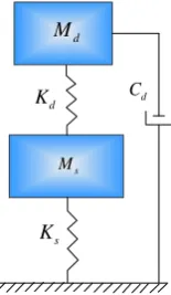
In this section, the adopted DVA model is described with a damper component connected to earth, as suggest by Ren [14]. The schematic diagram of the approach is shown in Figure 1, where the mass, stiffness and damping parameters of the appended DVA’s are denoted as Md, Kd and Cd respectively and the main structure’s parameters are denoted as Ms and Ks. The damping Cd is considered to be a linear viscous model, which is frequency independent (Figure 1).
s
M
s K
d
K
d M
d
C
Figure 1. Modified DVA model with damper connected to the
earth
The mechanical domain and electrical domain can be related by the impedance method.
In the Laplace domain, the impedance of a mass component is:
m
Z sM (1)
The impedance of a damper component is:
c
Z c (2)
The impedance of a spring component is:
k
K Z
s
(3)
Furthermore, if the mechanical impedance is considered from the standpoint of electric circuit theory, the mass behaves like an inductor, the damper behaves like a resistor and the spring behaves like a capacitor. The disturbance force and velocity items can also be represented by a voltage source and electrical current respectively.
Correspondingly, the DVA’s model as illustrated in Figure 1 can be represented by an electrical circuit, as shown in Figure 2. The left part is the main structure subjected to an external disturbance; the right part is the coupled DVA system. A linear electrical transformer represents the coupling of the two systems. The coupling coefficient is
.s
C Ls Rs
p
C
disturbance
F
L
R
p
v vp
p
Z
Figure 2. Electric circuit representation of the overall DVA
The velocity of the structure xand the disturbance force
disturbance
F are related by:
1 1
s
disturbance s couple s couple
Y x
F Z Z Y Z (4)
where, Zs is the impedance of the main structure,
couple
Z is the equivalent impedance of the DVA to the main structure, Ys is the mobility of the main structure, which is the reciprocal of the impedance.
3. ACTIVE CONTROL LAW FORMULATION
The general active control diagram employing velocity feedback is shown in Figure 3. When the sensing signal is velocity (x), and if the controller generates secondary force (Fpiezo) to the structure, the controller can be represented by an impedance model:
piezo
controller impedance
F
H Z
x
(5)
The closed loop transfer function of the feedback system is:
( )
1 ( ) ( )
s
disturbance s G s x
F G s H s (6)
Notably, the transfer function of the plant is actually the mechanical mobility representation in a Laplace domain.
According to Equation (4) and Equation (6), the coupling impedance item described in Equation (4) can be chosen using the active control law. The detailed form of the impedance coupled to the main structure can be written as:
2 2 2 1 ( ) 1 p p couple p p R s C LC
Z s Z
R s s L LC
(7)
Plant Controller
x
piezoF
disturbance F ( ) s G s ( ) H sFigure 3. Schematic diagram of the feedback control system
Furthermore, Equation (7) can be represented using the damping ratio and natural frequency parameters, as shown in Equation (8).
2 2 2 2 2 ( ) ( ) 2 2 controller couple d d n d
d d n n
d d
H j Z j
C s
M j
K k
C K j
s s M M (8)
The parameter
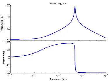
n determines the filter’s cut-off frequency. Generally, the active control outperforms passive damping treatment below 500 Hz [15]. Thus, a 500 Hz cut-off frequency is appropriate.The second parameter is the damping ratio. When the damping ratio is small, the DVA controller will have a resonance response at
n. Correspondingly, the phase response at this frequency is zero degree (Figure 4), which indicates that active skyhook damping is generated at this specific frequency.As the DVA control law is digitally implemented, the damping ratio can be flexibly tuned. An interesting phenomenon can occur when the damping ratio is gradually increased. The phase response of the controller will approach a zero degree bellows the cut-off frequency, which indicates that a wide band damping mechanism is generating to the host structure.
The damping ratio also relates the gain and phase transition of the control law. If this parameter is too small, the control authority of the low frequency band will not be sufficiently strong. If this parameter is too large, although the control authority could be guaranteed, the phase lag in the low frequency band will be larger than in small damping cases, which will indicate the possibility of more control spill-over. A damping ratio of 0.7 can be treated as a proper balancing point.
The synthesized control law’s Bode plot is shown in Figure 5.
Figure 4. Bode plot of the DVA controller with a damping
Figure 5. Bode plot of the proposed control law with different damping ratios
Finally, the control gain is usually normalized to have a 6 dB gain margin, which can be determined experimentally.
When the acceleration is chosen as the sensing signal, Equation (8) will be further involved:
2
2 2
2 ( )
( 2 )
n controller
n n
j
H j k
j j
(9)
4. EXPERIMENTAL SYSTEM SETUP AND OPEN-LOOP ANALYSIS
4. 1. Experimental System Arrangement To verify the effectiveness of the proposed control law, an experimental validation was initiated. The experimental system was composed of three parts:
(1) An aluminum plate (480 mm×480 mm) with a thickness of 1 mm was selected as the control plant; (2) An aluminum frame restricted the movement of the panel.
(3) A 6.5 inch loudspeaker was placed inside a PMMA (polymethyl methacrylate) cavity to serve as the vibration generator.
The generated disturbance was treated as a plane wave excitation in the low frequencies, so that the odd-odd modes can be efficiently excited [16]. These modes provided a significant contribution to the far-field sound radiation.
A piezoelectric actuator was attached to the center of the plate, which was used to suppress the structure’s odd-odd modes at low frequencies. A lightweight accelerometer (PCB Inc., 352a56, 1.5 gram) was used for error sensing. The accelerometer was located at the center of the piezoelectric patch. The signal conditioner type was B&K 2693. Finally, the complete experimental system is shown in Figure 6.
4. 2. Open-loop Frequency Response Analysis Theoretically, since the active control law is derived
Figure 6. Experimental system setup
from the passive vibration control method, it is unconditionally stable when the actuator and sensor are perfectly collocated. In actual operation; however, many factors influence the performance, as detailed in the Introduction.
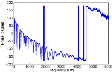
The measured open-loop control system’s phase frequency response is shown in Figure 7. Ideally, the designed control law detailed in Section 3 will introduce a 90 degree phase lag in the open-loop response and the phase response will never attain -180 degrees. In reality; however, it was found that the phase lag will finally exceed -180 degrees at 1.8 kHz, which indicated the finite gain margin of the control law.
A further test of the control law was to examine the controller’s roll-off property. A performance comparison was conducted between the DVF with DVA controllers and the measured open loop frequency responses of each are shown in Figure 8.
According to Figure 8, the DVA control law appeared to generate sufficient roll off at high frequencies, a property that is especially favorable for the piezoelectric actuator, which usually has better compliance at high frequency than at low frequency.
Figure 8. Frequency response comparisons (solid red line: DVF control law; dashed blue line: DVA control law)
In addition, the proposed DVA control, can anticipate spillover which was not the case with the DVF control law.
5. EXPERIMENTAL CLOSE-LOOP CONTROL ANALYSIS
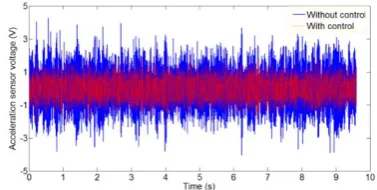
5. 1. Vibration Control Results The active control results are summarized as shown in the following figures. Figure 9 shows the uncontrolled and controlled acceleration signals in over time. Figure 10 summarizes the performance of the active control over a variety of frequencies of disturbance.
Figure 9. Measured accelerometer’s response in time domain
(solid line: measured acceleration signal without control; dashed line: measured acceleration signal with control)
Figure 10. Measured accelerometer’s response with frequency
(solid line: uncontrolled acceleration signal; dashed line: controlled acceleration signal)
As shown in these figures, it appeared that the synthesized controller was very effective in the designed frequency band below 500 Hz. For instance, the 1-1 mode at 53.2 Hz was suppressed by 10.75 dB, while the 1-3 vibration mode at 153.1 Hz was reduced by 13.27 dB. In addition, many other vibration modes below 500 Hz were also well controlled. A little control spill-over was observed around 830 Hz, which was due to the phase lag that existed in the control loop.
5. 2. Acoustic Control Results To evaluate the noise isolation performance, the test structure was placed inside an anechoic chamber, which had net dimensions of 3m3m2.5m. A microphone sensor (50 mv/Pa, G.R.A.S) was located at the upper side of the plate. The distance from the microphone sensor to the plate was about 50 cm, which met the far-field sound filed condition (Figure 11).
The measured sound pressure levels with and without control are given in Figure 12. The sound pressure level at 53 Hz was lowered by 11 dB; another dominant peak at 153 Hz was lowered by 14 dB. The global sound pressure level below 1 kHz was reduced by 6.2 dB after active control.
Figure 11. Sound isolation tests in the anechoic chamber
Figure 12. Measured sound pressure level (solid line:
6. CONCLUSIONS
In this study, an investigation was conducted of a vibro-acoustic control of a plate under stochastic disturbance. Active DVA control law was designed and tested experimentally. The actuator was a PZT patch and the sensor was an accelerometer.
The theoretical derivation showed that the proposed DVA controller exhibited a roll-off property, easy implementation and wideband damping character. This attribute is desirable for piezoelectric smart vibro-acoustic control application. Further real-time control testing results proved its effective under wide band stochastic disturbances. Effective noise and vibration suppression can be achieved when the active control system was initiated.
Another contribution of the experimental results showed that the proposed control law did not involve complex finite element or experimental system identification modeling steps. Accordingly, it can be rapidly deployed to complex structures with small damping ratio character. The simple implementation form also implies the computation is less intensive compared to sophisticated model-based control laws. The overall system can be made compact and costeffective, which is suitable for commercial application.
Finally, it is also suggested that other forms of DVA controllers are worth investigation for further study.
7. ACKNOWLEDGEMENT
The author sincerely thanks the anonymous reviewers for their valuable comments that have led to the present improved version of the original article.
This research is sponsored by the Natural Science
Foundation of Jiangsu Province (Grant No.
BK20160895) &NUPTSF (Grant No. NY215009).
8. REFERENCES
1. Ohayon, R. and Soize, C., "Structural acoustics and vibration: Mechanical models, variational formulations and discretization, Elsevier, (1997).
2. Fuller, C.C., Elliott, S. and Nelson, P.A., "Active control of vibration, Academic Press, (1996).
3. Schiller, N.H., Cabell, R.H. and Fuller, C.R., "Decentralized control of sound radiation using iterative loop recovery", The Journal of the Acoustical Society of America, Vol. 128, No. 4, (2010), 1729-1737.
4. Khoshnood, A.M. and Kavianipour, O., "Vibration suppression of fuel sloshing using subband adaptive filtering", International Journal of Engineering, Transactions A: Basics, Vol. 28, No. 10, (2015), 1507-1514.
5. Moghadam-Fard, H. and Samadi, F., "Active suspension system control using adaptive neuro fuzzy (anfis) controller",
International Journal of Engineering-Transactions C: Aspects, Vol. 28, No. 3, (2014), 396-401.
6. Yuan, M., "Field programmable gate array implementation of active control laws for multi-mode vibration damping",
International Journal of Engineering-Transactions B: Applications, Vol. 29, No. 2, (2016), 229-235.
7. Li, S., Li, J. and Mo, Y., "Piezoelectric multimode vibration control for stiffened plate using adrc-based acceleration compensation", IEEE Transactions on Industrial Electronics, Vol. 61, No. 12, (2014), 6892-6902.
8. Yuan, M., Ohayon, R. and Qiu, J., "Decentralized active control of turbulent boundary induced noise and vibration: A numerical investigation", Journal of Vibration and Control, (2015). 9. Balas, M.J., "Direct velocity feedback control of large space
structures", Journal of Guidance, Control, and Dynamics, Vol. 2, No. 3, (1979), 252-253.
10. Gardonio, P., Bianchi, E. and Elliott, S., "Smart panel with multiple decentralized units for the control of sound transmission. Part ii: Design of the decentralized control units",
Journal of Sound and Vibration, Vol. 274, No. 1, (2004), 193-213.
11. Poh, S. and Baz, A., "Active control of a flexible structure using a modal positive position feedback controller", Journal of Intelligent Material Systems and Structures, Vol. 1, No. 3, (1990), 273-288.
12. Wang, Y. and Inman, D.J., "Comparison of control laws for vibration suppression based on energy consumption", Journal of Intelligent Material Systems and Structures, Vol.22, No. 8, (2011), 795-809.
13. Kim, S.-M., Pietrzko, S. and Brennan, M.J., "Active vibration isolation using an electrical damper or an electrical dynamic absorber", IEEE Transactions on Control Systems Technology, Vol. 16, No. 2, (2008), 245-254.
14. Ren, M., "A variant design of the dynamic vibration absorber",
Journal of Sound and Vibration, Vol. 245, No. 4, (2001), 762-770.
15. Rohlfing, J., Gardonio, P. and Thompson, D., "Comparison of decentralized velocity feedback control for thin homogeneous and stiff sandwich panels using electrodynamic proof-mass actuators", Journal of Sound and Vibration, Vol. 330, No. 5, (2011), 843-867.
Compact and Efficient Active Vibro-acoustic Control of a Smart Plate Structure
M. Yuan
College of Automation, Nanjing University of Posts and Telecommunications, Nanjing, China
P A P E R I N F O
Paper history: Received 29 April 2016
Received in revised form 22 June 2016 Accepted 14 July 2016
Keywords: Noise Isolation Vibration Control Smart Structure Active Control
ديكچ ه
ایًپ شاعترا زىف عًو کی ساسا زب لاعف لزتىک نًواق ،زثًم ٌدزتسگ دواب
(DVA)
اب .دش یسرزب ٍعلاطم هیا رد ي داُىشیپ
لزتىک نًواق کی ،یکیواکم سوادپما شير سا ٌدافتسا
DVA
.دش ٍلًمزف لعفىم یکیواکم لدم ساسا زب لاعف
DVA
ٍب یکیزتکلا ٍحفص کی ،نابشیم راتخاس .دًب نآ قیقد راتخاس رد لاعف ییازیم تلاح دىچ دیلًت ٍب رداق ٌدمآ تسد
اب یشیامسآ متسیس .دًب یددع ترًصب کیزتکلايشیپ کزحم کی ٍب ٍیذغت لزتىک قیزط سا باتش لاىگیس کی اب یمًیىیمًلآ سا ٌدافتسا
DVA
ٍک داد ناشو ساب ٍقلح لیلحت ي ٍیشجت ي دش ٍتخاس ٍب تبسو یزتُب ندزک لير تیصاخ ،لزتىک متسیس
کبدیف تعزس لزتىک میقتسم
(DVF)
ددعتم یاَ شسزل تلاح ٍک داد ناشو یعقاي نامس لزتىک جیاتو ،هیا زب ٌيلاع .دراد
زیس ٌدش یزیگ ٌسادوا یادص یساسادج دزکلمع ،هیا زب ٌيلاع .دًش بًکزس نامشمَ رًط ٍب دواًت یم 1
یاراد شتزَ ًلیک
دقم ٌسادوا ٍب ي لااب را 6
ازجا لباق ٌساس عاًوا یازب یتحار ٍب ي تسا زثًم ي ٌداس ٌدش ٍئارا شير .دمآ تسد ٍب لب یسد
تسا