University of Windsor University of Windsor
Scholarship at UWindsor
Scholarship at UWindsor
Electronic Theses and Dissertations Theses, Dissertations, and Major Papers
2009
Optimal channel assignment and power control in wireless
Optimal channel assignment and power control in wireless
cellular networks
cellular networks
Xin Yu
University of Windsor
Follow this and additional works at: https://scholar.uwindsor.ca/etd
Recommended Citation Recommended Citation
Yu, Xin, "Optimal channel assignment and power control in wireless cellular networks" (2009). Electronic Theses and Dissertations. 8049.
https://scholar.uwindsor.ca/etd/8049
This online database contains the full-text of PhD dissertations and Masters’ theses of University of Windsor students from 1954 forward. These documents are made available for personal study and research purposes only, in accordance with the Canadian Copyright Act and the Creative Commons license—CC BY-NC-ND (Attribution, Non-Commercial, No Derivative Works). Under this license, works must always be attributed to the copyright holder (original author), cannot be used for any commercial purposes, and may not be altered. Any other use would require the permission of the copyright holder. Students may inquire about withdrawing their dissertation and/or thesis from this database. For additional inquiries, please contact the repository administrator via email
OPTIMAL CHANNEL ASSIGNMENT AND POWER
CONTROL IN WIRELESS CELLULAR NETWORKS
BY
X I N W U
A Thesis
Submitted to the Faculty of Graduate Studies through the School of Computer Science in Partial Fulfillment of the Requirements for
the Degree of Master of Science at the University of Windsor
Windsor, Ontario, Canada
2009
1*1
Library and Archives CanadaPublished Heritage Branch
395 Wellington Street OttawaONK1A0N4 Canada
Bibliotheque et Archives Canada Direction du
Patrimoine de I'edition 395, rue Wellington Ottawa ON K1A 0N4 Canada
Your file Votre r§f6rence ISBN: 978-0-494-57564-2 Our file Notre reference ISBN: 978-0-494-57564-2
NOTICE:
The author has granted a
non-exclusive license allowing Library and Archives Canada to reproduce, publish, archive, preserve, conserve, communicate to the public by
telecommunication or on the Internet, loan, distribute and sell theses
worldwide, for commercial or non-commercial purposes, in microform, paper, electronic and/or any other formats.
AVIS:
L'auteur a accorde une licence non exclusive permettant a la Bibliotheque et Archives Canada de reproduce, publier, archiver, sauvegarder, conserver, transmettre au public par telecommunication ou par I'lnternet, preter, distribuer et vendre des theses partout dans le monde, a des fins commerciales ou autres, sur support microforme, papier, electronique et/ou autres formats.
The author retains copyright ownership and moral rights in this thesis. Neither the thesis nor substantial extracts from it may be printed or otherwise reproduced without the author's permission.
L'auteur conserve la propriete du droit d'auteur et des droits moraux qui protege cette these. Ni la these ni des extraits substantias de celle-ci ne doivent etre imprimes ou autrement
reproduits sans son autorisation.
In compliance with the Canadian Privacy Act some supporting forms may have been removed from this thesis.
Conformement a la loi canadienne sur la protection de la vie privee, quelques formulaires secondaires ont ete enleves de cette these.
While these forms may be included in the document page count, their removal does not represent any loss of content from the thesis.
Bien que ces formulaires aient inclus dans la pagination, il n'y aura aucun contenu manquant.
Author's Declaration of Originality
I hereby certify that I am the sole author of this thesis and that no part of this thesis has been published or submitted for publication.
I certify that, to the best of my knowledge, my thesis does not infringe upon anyone's copyright nor violate any proprietary rights and that any ideas, techniques, quotations, or any other material from the work of other people included in my thesis, published or otherwise, are fully acknowledged in accordance with the standard referencing practices. Furthermore, to the extent that I have included copyrighted material that surpasses the bounds of fair dealing within the meaning of the Canada Copyright Act, I certify that I have obtained a written permission from the copyright owner(s) to include such material(s) in my thesis and have included copies of such copyright clearances to my appendix.
Abstract
Wireless mobile communication is a fast growing field in current telecommunication industry. In a wireless cellular network, channel assignment is a mechanism that assigns channels to mobile users in order to establish a communication between a mobile terminal and a base station. It is important to determine an optimal allocation of channels that makes effective use of channels and minimizes call-blocking and call-dropping probabilities. Another important issue, the power control, is a problem of determining an optimal allocation of power levels to transmitters such that the power consumption is minimized while signal quality is maintained. In wireless mobile networks, channels and transmitter powers are limited resources. Therefore, efficient utilization of both those resources can significantly increase the capacity of network.
Dedication
To those who brightened me To those who warmed me To those who emboldened me To the one who showed me the way
Acknowledgements
I would like to take this opportunity to express my sincere gratitude to my supervisor, Dr.
Arunita Jaekel, for her patience, amiability and constant support throughout my graduate
studies. Under her supervision and guidance, I have the chance to develop my analytical
and organizational skills in research.
I am grateful to the committee members, Dr. Jessica Chen, Dr. Chunhong Chen and
Dr. Subir Bandyopadhyay for their valuable advises and constructive criticism.
A special thank also goes to the Graduate Secretary of School of Computer Science,
Ms. Mandy Turkalj, for her warm and sincere help and assistance during my study.
Last, but not least, I would like to thank my family and all my friends for their
Table of Contents
Author's Declaration of Originality iii
Abstract iv
Dedication v
Acknowledgements vi
List of Tables ix
List of Figures x
1. Introduction 1 1.1. Mobile Communication 1
1.2. Problem Statement 3 1.3. Contributions 4 1.4. Organization of Thesis 5
2. Background Information 6 2.1. Cellular System Architecture 6
2.2. Communication Channel 7 2.3. Channel Assignment 8
2.3.1. Channel Reuse 9 2.3.2. Channel Assignment Scheme 11
2.3.3. Channel Assignment Constraints 13
2.4. Power Control 15
3. Proposed ILP Methodology 19
3.1. General 19 3.2. HCA Strategy 20
3.2.2. ILP without Channel Reassignment (ILP1) 22 3.2.3. ILP with Channel Reassignment (ILP2) 24
3.3. HCA Integrated with Power Control 26
3.3.1. Notation (NT2) 27 3.3.2. ILP without Channel Reassignment (ILP3) 28
3.3.3. ILP with Channel Reassignment (ILP4) 30
4. Simulation and Results 32 4.1. Cellular Model Assumptions 32
4.2. Traffic Model 34 4.3. Implementation Details 36
4.3.1. Processing Call Event 36 4.3.2. Determination of Allocation Matrix 38
4.3.3. Determination of Distance between Cells 39 4.3.4. Determination of Link Gain Matrix 39
4.4. Experimental Results 40
5. Conclusion and Future Work 49
Bibliography 51
List of Tables
Table 4.1: Blocking probabilities of ILPl 41
List of Figures
Figure 2.1: Atypical cellular system architecture 7
Figure 2.2: Reuse distance 10 Figure 2.3: Reuse pattern (reuse distance is 3) 10
Figure 2.4: System geometry and link gains 16 Figure 4.1: Cellular topological model 33 Figure 4.2: Non-uniform traffic distribution pattern 1 with initial arrival rates 35
Figure 4.3: Non-uniform traffic distribution pattern 2 with initial arrival rates 36
Figure 4.4: Processing call arrival event 37 Figure 4.5: Processing call release event 38 Figure 4.6: Distance between two cells 39 Figure 4.7: Blocking probabilities of ILP2 forg=2 and w=2 41
Figure4.8: Performances of ILP2 for ratio 21:49 42 Figure 4.9: Performances of ILP1 vs. ILP2 for ratio 21:49 with initial traffic load 43
1. Introduction
1.1. Mobile Communication
In recent years, due to the tremendous growth in the demand of communication services,
there has been a great development in the area of communication technologies, especially,
the wireless cellular networks.
In a cellular system, according to the cellular principle, a geographical area is
partitioned into cells where each of them has a base station and contains a number of
mobile terminals, for example, mobile phones. The base station is equipped with radio
transmission and reception equipment, responsible for the communication between a
mobile terminal and the rest of the network. A group of base stations are connected to the
Mobile Switching Center (MSC), which connects the cellular network to other wired or
wireless information networks.
To begin communication with a base station, a mobile terminal must obtain a
channel from the base station, where a channel consists of a pair of frequencies: one
and another frequency (the up-link) for the transmission in the reverse direction. The
channel assignment problem deals with assigning an appropriate channel for each
communication request, in another word, the new incoming call, that arrives in a cell. In
order to mitigate radio frequency interference between channels, the selected channel
must satisfy some electromagnetic compatibility constraints [1], also referred to as hard
constraints, namely co-channel constraint (CCC), co-site constraint (CSC) and adjacent
channel constraint (ACC).
Generally, channel assignment schemes are divided into three categories, fixed
channel assignment (FCA), dynamic channel assignment (DCA) and hybrid channel
assignment (HCA). In FCA, a fixed number of channels are assigned to each cell
beforehand based on pre-estimated traffic load. In another hand, in DCA, channels are
dynamically allocated based on incoming calls and the current network configuration. As
a hybrid, HCA is a combination of FCA and DCA.
In addition to radio frequency, power of transmitters is another kind of scarce
resources in mobile communications. The power control problem deals with assignment
of an appropriate power level to the terminal at which the incoming call rises, with the
objective of minimizing total power consumption and suppressing interference.
It is important to have a resource management scheme that can allocate these limited
resources fairly and efficiently, but both the channel assignment and the power control
problems, by themselves, are known to be difficult problems [2], [3]. Therefore, many
instance, first a channel is selected, and then a power control algorithm is used to check
and update the carrier-to-interference ratio (CIR) value of the channel.
1.2. Problem Statement
In this thesis we present two sets of optimal integer linear programming (ILP)
formulation (four formulations in total) that are used in the Hybrid Channel Assignment
approach in wireless cellular networks. The first set of formulation does not consider
power control; while the second set of formulation integrates channel assignment with
power control. Our approach can also be easily applied to the Dynamic Channel
Assignment problem as well.
For the channel assignment which does not cooperate with power management,
many existing schemes solve a simplified version of the problem that only addresses the
co-channel constraint [6], [7]. Our approach not only handles all three mandatory
constraints, it also takes into consideration as well some optional conditions which are
beneficial to the performance. The first formulation in this series does not involve
reassignment of existing calls in the cell, while the second formulation allows such
reassignment to further reduce the blocking probability.
When considering power control, in order to meet the required signal quality
specifications, the assigned channel and its power level (for the incoming call) should be
maintained above an acceptable level. Existing techniques typically use heuristics to solve
this problem, which generally leads to sup-optimal solutions. To improve this, we present
the second set of formulations that can be used to optimally solve combined HCA and
power control problem. They ensure that the CIR requirements are met, not only for the
new incoming call but also for all ongoing calls using the same channel. This means that,
unlike many previous approaches [8], [9], [10], the call dropping probability due to an
incoming call is zero, because if CIR requirements can not be reached for all ongoing
calls, then the new call is simply blocked. Furthermore, our approach specifies an
appropriate power level to the incoming call and all ongoing calls using the selected
channel such that the overall power consumption is minimized, leading to a significant
reduction in blocking probability.
1.3. Contributions
Our contributions are summarized as follows.
1. A set of efficient Integer Linear Programming formulations for the optimization
problem of channel assignment considering several kinds of radio interference
constraints simultaneously, including co-channel constraint, co-site constraint and
adjacent channel constraint.
2. An original, novel and efficient Integer Linear Programming approach to incorporate
resource management are fully integrated and are performed in one step, leading to a
zero call dropping probability which is due to the entrance of an incoming call.
3. A set of efficient Integer Linear Programming formulations which guarantee that the
selection of channels always meets the CIR requirements and optimal power is
achieved.
4. Consider both non-reassignment and reassignment of channels, and compare their
performances for our specific problem.
1.4. Organization of Thesis
In chapter 2, we give some background information in wireless mobile communication,
such as system architecture, channel assignment, radio interference and power control.
Chapter 3 describes our Integer Linear Programming methodology for the problem of
finding an optimal channel assignment with and without power control, adopting channel
reassignment and not. Chapter 4 addresses basic assumptions of the cellular model used
in the simulation, as well as implementation details and experimental results. At last,
2. Background Information
2.1. Cellular System Architecture
A typical cellular system architecture is illustrated in Figure 2.1. The covered
geographical area is divided into many small service areas named cells [11]. In practical
environment, the cell sizes are irregular and depend on the terrain and radio wave
propagation conditions.
Each cell has a base station, associating with many mobile terminals, such as mobile
phones, laptops and palms. The base station is usually placed in the center of a cell and
has its own transmission capability with radio equipments. The mobile terminals
communicate through wireless links with the base station located within the cell.
The base station provides an interface between the mobile units scattered across a
cell and the Mobile Switching Center (MSC) which is also known as Mobile Telephone
Switch Office (MTSO). The MSC plays as the central coordinating element for all cell
sites, controlling call processing, handling billing activities, performing channel
Public Switching Telephone Network (PSTN). In short, the base station is responsible for
the communication between mobile terminal and the rest of network.
Mobile Switching
Center (MSC)
Public Switching Telephone Network
(PSTN)
X
Figure 2.1: Atypical cellular system architecture
A base station can communicate with mobile terminals as long as they are in its
range of operation. The operating range depends upon the transmission power of the base
station, and the radio energy dissipated per unit distance.
2.2. Communication Channel
When a call arrives in a particular cell, it will be assigned to a channel. A mobile user
actually needs two channels: one for the mobile to base station link (or uplink), and
another for the base station to mobile link (or downlink). As these two channels are
single link in many studies. This ideal channel is considered as an ordinary
communication resource, depending on the multiple access technique used by the cellular
network. In practice, it could be a fixed radio frequency for a frequency division multiple
access (FDMA), or a particular time slot within a frame for a time division multiple
access (TDMA), or a specific code for a code division multiple access (CDMA) [11].
2.3. Channel Assignment
The capacity of a cellular system could be described in terms of the number of available
channels, or, more effectively, the number of users that the system can support. The total
number of channels available to the system is determined on the pre-allocated spectrum
quota and the bandwidth of each channel. Since the number of available channels is
limited while the number of mobile terminals is exponentially increasing, the channel
must be reused as much as possible in order to increase the system capacity. This requires
a proper channel assignment mechanism which involves allocating channels to cells or
mobiles in a network efficiently, while satisfying the electromagnetic compatibility.
In general, channel assignment problems may be modeled as optimization problems
which have the following form. Given a collection of radio terminals to be allocated
operating channels, find an assignment that satisfies various constraints and minimizes
the value of a given objective function. The work in [3] has shown that the assignment
2.3.1. Channel Reuse
As the reuse of channels is inevitable in a cellular system, channels used at one cell site
may also be used at other cell sites in the case of absence of co-channel interference.
Co-channel interference is radio interference caused due to the allocation of same channel
to certain pairs of cells with geographical separation not enough to avoid deterioration of
signal quality. The minimum distance required between the centers of two cells using the
same channel to maintain the desired signal quality, is known as the reuse distance [7],
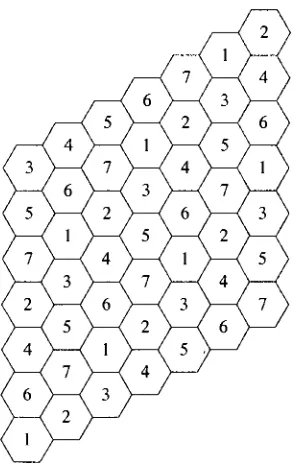
[11], [12], [13], [14]. As shown in Figure 2.2, for example, if the reuse distance is 3, the
cells in gray can not use the same channels occupied by cell x, because their distances to
cell x are less than 3. Figure 2.3 shows a reuse pattern in which the cells with same
number belong to the same reuse scheme and are free from co-channel interference,
according to the reuse distance equal to 3. This reuse scheme is obtained by jumping from
one cell to another in steps of length equal to the reuse distance [11], [15], [16].
The longer the reuse distance is, the smaller will be the co-channel interference level.
However, a long reuse distance may result in lower reuse efficiency [15]. Thus, the
frequency reuse scheme should be determined taking into consideration both the
Figure 2.2: Reuse distance
Figure 2.3: Reuse pattern (reuse distance is 3)
Traditionally, channel assignment is made according to the co-channel interference
level determined by a fixed reuse distance which is decided during network planning.
Many approaches proposed in literature to solve channel allocation problem are based on
2.3.2. Channel Assignment Scheme
The channel assignment problem concerns allocating frequencies, for example, in a
FDMA system, to mobile terminals and base stations such that the signal quality is
guaranteed and network capacity is maximized. This is a difficult problem and has been
widely investigated in literature. Various channel assignment schemes have been studied
broadly to find better ways to assign channels to calls and to achieve higher level of
channel reuse. Proposed schemes are mainly classified into two categories, Fixed Channel
Assignment and Dynamic Channel Assignment.
In FCA, the set of channels are permanently allocated to each cell in advance
according to the pre-estimated traffic intensity [18], [19], [20], [21], [22]. In a cell, a call
can be assigned to a channel only if there is a free channel available in the predetermined
set for this cell. Otherwise, the call might be rejected even though there are many
channels available in the network.
In DCA, there is no permanent allocation of channels to cells. Instead, the whole set
of available channels is accessible to all the cells, and the channels are assigned on a
call-by-call basis in a dynamic manner [23], [24], [25], [28], [29], [30], [31]. Since a cell
can use any of channels in a dynamic way, it is possible that if a cell uses all channels at a
given time then there will not be any channel available to its neighboring cells at that time
due to interference.
user distribution. Furthermore, the channel pre-allocation is difficult as it is based on the
accurate knowledge of interference condition. These weaknesses are overcome by DCA.
DCA makes cellular system more efficient in practice where the traffic load distribution is
unknown beforehand or varies with time. The main advantages of DCA are the flexibility
and the traffic adaptability, since channel assignment is made according to the current
network conditions. DCA methods have better performance than FCA methods for light
to medium traffic load [7], but it performs not so well under heavy load conditions.
Furthermore, it requires more complex control and is relatively more time consuming
[11].
Most of proposed DCA algorithms are heuristic based and do not guarantee an
optimal solution. In addition, many existing DCA schemes consider a simplified problem
with only co-channel constraint [23], [24], [25], [29], [30], [31], [32], [33]. Recently,
DCA schemes for multi-hop wireless communications [40], [41], [42], [43] have also
been proposed.
Many extensions and combinations of above two essential schemes have been
studied in literature. The most basic are Hybrid Channel Assignment and Borrowing
Channel Assignment (BCA).
The HCA [6], [7], [17], [44], [45] combines the features of both FCA and DCA
techniques to overcome their drawbacks. In HCA, the set of channels is divided into two
subsets [7], the Fixed Channel (FC) set in which channels are permanently allocated to
The ratio of the number of channels in each set is fixed a priori by the cellular network
designer. For example, the representative ratios, FC:DC, for 70 channels in total, could be
35:35, 49:21 or 21:49. If FC is empty, then the HCA problem reduces to the classical
DCA problem. When a new call arrives in a cell, the system first tries to serve it from the
set of fixed channels. If no channel is available in the set of fixed channels, then the DCA
scheme determines a suitable channel from the set of dynamic channels, satisfying the
interference constraints and the traffic demands in cells.
In BCA [39], the channel assignment is initially fixed. When incoming calls arrive in
a cell whose channels are all occupied, the cell borrows channels from its neighboring
cells, and thus the call blocking is prevented [11].
2.3.3. Channel Assignment Constraints
Radio transmission in a channel may cause interference in other channels. Such
interferences degrade the signal quality and hence the quality of service (QoS). In order to
alleviate radio frequency interference between channels, the selected channel must satisfy
the following electromagnetic compatibility constraints [1] which are also referred to as
hard constraints.
1. Co-channel constraint (CCC)
The same channel cannot be assigned to two cells that are separated by a distance less
2. Co-site constraint (CSC)
Channels used in the same cell must be separated by a minimum amount, that is, their
radio frequencies must be far enough apart.
3. Adjacent channel constraint (ACC)
Channels assigned to neighboring cells must be separated by a minimum amount.
In addition to the above hard constraints, there are a number of other conditions,
which may be taken into consideration to improve the performance of the channel
allocation technique. Such conditions are called soft constraints and could be violated if
necessary [26]. They are described as follows.
1. Packing condition
Try to use the minimum number of channels every time a call arrives [11]. This
condition encourages the selection of channels already in use in other cells as long as
the hard constraints are satisfied.
2. Resonance condition
Try to assign the same channels to cells that belong to the same reuse scheme [11].
The purpose of this approach is to leave as many channels as possible to be allocated
to other cells belonging to other reuse scheme. Consequently, the probability of
causing co-channel interference in the system is reduced.
3. Limiting rearrangement
calls, thus limiting the reassignment of channels. Channel reassignment is the process
of transferring an ongoing call to a new channel without call interruption [27]. Such
reassignment in the entire cellular network upon the arrival of a new call will
obviously result in lower call blocking probability, but it is complex both in terms of
time and computation [11]. Therefore, the reassignment processes should be limited
to a low level. On this account, limiting rearrangement condition is used to prevent
excessive reassignment in a cell [11].
2.4. Power Control
To support communication, power must be supplied to transmitters. Owing to the scarcity
of transmitter power, excessive use of power for transmission causes a faster drainage of
power, resulting in short battery life. Furthermore, it will raise the interference to other
users. In a wireless network, the signal quality is usually determined by
Carrier-to-interference Ratio (CIR), which is also known as Signal-to-Interference Ratio
(SIR). Carrier represents the signal power received by a receiver from the transmitter in
the cell where it is located, while interference represents the cumulative effect of signal
powers from other transmitters using the same channel [7]. The signal quality and the
level of interference in the wireless network depend upon the transmitter power levels.
Power control is a resource management process that is used to adjust transmission
consumption are minimized. Due to its ability to suppress the co-channel and adjacent
channel interference, power control can increase the network capacity.
Let us consider a situation under which a set of N transmitter-receiver pairs are using
the same channel /. As mentioned before, the uplink and downlink, in another word,
mobile-to-base frequency and base-to-mobile frequency, used by one communication are
assumed not to interfere with each other and are allocated in the same manner. Here, in
this thesis, we only consider the downlink frequency allocation. All the results in this
thesis could be applied to the uplink easily. The relevant propagation effects are modeled
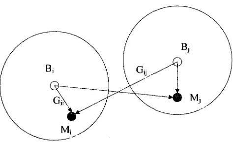
by link gains, as illustrated in Figure 2.4. The link gain (actually power loss) from the
transmitter of one link to the receiver of another link includes free space loss, multipath
fading and other radio wave propagation effects [6].
Figure 2.4: System geometry and link gains
Let Bj and Mj denote the base station and mobile terminal respectively in cell j , and
using the same channel in cell /. The gain G„ corresponds to the desired communication
link, whereas Gy (i^j) corresponds to unwanted co-channel interferences. Let pji be the
transmitter power on channel / at base station Bj. The signal power received at the
receiver of Mt on the same channel, from the base station transmitter in cell j , is GtJ • p fl.
The desired signal power at the receiver in cell i is equal to GH • p}l, while the total
interfering signal power from other transmitters (using the same channel / for ongoing calls in their respective cells) to the receiver in cell i is ^Gy • pjt. As in [3], we use the
CIR of Mi (denoted by TJ.) as measure of the signal quality at mobile Mi.
where rjj >0 is the thermal noise power at mobile M,. The CIR is acceptable if T) is
above a certain threshold, y0, called the minimum protection ratio. This y0 reflects
some minimum QoS that the link must support throughout the transmission in order to
operate properly. Hence, for acceptable CIR, we have:
The objective of power control is to maintain the CIR requirements (2.2) for all ongoing
and incoming calls.
Both power control schemes and DCA approaches are considered as the most
efficient techniques to manage scarce resource available to the system [2], [4], [5], [34],
distributed. Many researches demonstrated that a remarkable improvement in terms of
spectrum efficiency and network capacity could be gained via integrating these two
techniques together [36], [37], [38], but lots of them take an incompact way of integration,
for example, finding proper channels firstly and then applying power adjustment to
transmitters. Most existing PC-DCA algorithms such as those in [8], [9], [10], do not
guarantee that all existing calls will maintain the desired CIR. Though the works in [4], [5]
ensure that existing calls will not be dropped, they do not jointly optimize both channel
3. Proposed ILP Methodology
3.1. General
Channel assignment schemes help to increase the network's capacity by efficiently
distributing the channels across the network. Herein, we present our HCA approach
whose details are briefly described as follows.
We assume each base station in a cellular network has a computer that stores the
current state of its cell. The state of a cell includes information about channels, mobiles,
and ongoing calls in such cell. Each base station sends its state to other base stations
through a wired network between their computers. Channel assignment is made by the
computer of the concerned base station according to the channel usage information stored
in the allocation matrix. Letting C be the total number of cells in the network and L the
total number of channels, the allocation matrix A is a binary matrix of size CxL such that
{
1 if channel j is in use in cell /, 0 otherwise.network, and each base station receives a copy of the allocation matrix. The total number
of channels is divided into two sets, FC and DC. If FC is empty, then the problem reduces
to the classical DCA problem.
Our HCA approach works like this. When a call arrives in a cell k at time t, we first
search for a channel in the FC set that can serve the call. If no such channel is available
from FC then we apply our ILP formulations on the DC set to obtain a best assignment of
channels in cell k. The solution contains channels to be assigned to all ongoing calls in the
cell k (ongoing calls maybe re-assigned new channels, for ILP2 and ILP4) and the
channel to be assigned to the new call.
Following subsections address formulations which are used in above working frame.
3.2. HCA Strategy
In this part, we solve HCA problem based on reuse distance concept. Unlike most existing
techniques, we consider all the three hard constraints, that is, co-channel, co-site and
adjacent channel constraints, as well as the soft constraints. Our formulations are
described as follows.
3.2.1. Notation (NT1)
data.
k : Cell where a call arrives.
dk : Number of calls in cell k (traffic demand in cell k), including the
new call.
ro : Reuse distance.
r\ : Minimum distance between cells to avoid adjacent channel
interferences.
g : Co-site interference channel interval.
w : Adjacent site interference channel interval, g>w.
C : Number of cells in the network.
L : Number of dynamic channels.
B : Set {1, 2, ...,L} of channel numbers for all dynamic channels.
Bf : Subset of B, containing the channels currently not in use in cell
k.
K : Subset of B, containing the channels currently in use in cell i,
\<i<C.
"tj '• Normalized distance between cell / and celly, 1 < i, j < C.
res(i, j) : A function defined as follows:
res(i,j) =
1 if cell i and cell j belong to the same reuse scheme,
0 otherwise.
aij : An element of a CxL allocation matrix A, where each element,
aij, is defined as follows:
{
1 if channel j is in use in cell i, 0 otherwise.Wj, W2 and Ws: Positive constants.
1 if channel / is selected for the new call in cell k, V /e Bf,
1 I 0 otherwise.
1 if channel me B is selected for an existing call or the new
ym = ~\ call in cell k,
0 otherwise.
3.2.2. ILP without Channel Reassignment (ILP1)
We now present our first ILP formulation that allocates a free channel to a new call
without any reassignment of existing channels. Using the notation given above, we
formulate ILP 1 as follows.
Objective function:
c a. i • x,
Minimize -W, X X ^ T ^ + W2 X 5 > M '*' " 0 - " » & * ) ) (3.1) i=\,i*kleBf " ; , * i=\,i*kl^Bf
Subject to:
1. Constraint for one channel per call.
l^Bf
2. Co-channel constraint.
(3.2)
xt + au<\, VleBf, \<i<C, dik<r0, i*k (3.3)
3. Co-site constraint.
4. Adjacent channel constraint.
xt + aiq < 1, V/ € Bf, \/q&Kn \<i<C, i * k, dik<rx,
I, I i ( 3-5 )
|/ — q\ < w, I ^ q
In our formulation, the traffic demand and hard constraints are handled by equations
(3.2) - (3.5). There may be multiple channels that satisfy these constraints, but, among
them, the objective function specified in (3.1) selects one channel that best meets the
requirements of the soft constraints. W] and W2 are positive constants and determine the
relative significance of different terms. The first term expresses the packing condition.
The objective value decreases if channel / is also in use in cell / which is free from
co-channel interference with cell k. The decrease in the value depends upon the distance
between the cells / and k. The second term expresses the resonance condition. The
objective value decreases if channel / is also in use in cell /, and cells i and A: belong to the
same reuse scheme. Therefore, the objective function attempts to increase packing and
assign the same channel to cells that belong to the same reuse scheme.
Constraint (3.2) ensures that each call is allocated exactly one channel from the pool
of available dynamic channels that are currently not in use in cell k.
Constraint (3.3) enforces the co-channel constraint by ensuring that a channel /e i?/is
not selected for a call in cell k if it is already in use in any neighboring cell i, assuming i
and k are separated by a distance less than the reuse distance ro.
Constraint (3.4) is the co-site constraint. It ensures that a channel / is selected in cell
currently in use in cell k.
Constraint (3.5) states the adjacent channel constraint. It ensures that a channel / is
selected in cell k only if it is separated by at least the adjacent channel interval w, from
any other channel q, currently in use in a neighboring cell i, which is at a distance r;.
Normally, g> w and ro>ri.
3.2.3. ILP with Channel Reassignment (ILP2)
As mentioned before, channel reassignment, the process of transferring an ongoing call to
a new channel without call interruption [27], can improve the QoS by lowering call
blocking probability. Hence it is an important process in dynamic channel allocation. We
now present our second ILP formulation that makes use of reassignment of existing
channels. Using the notation given above, we formulate ILP2 as follows.
Objective function:
C C
Minimize -W
x£ £ ^ i k + ^ £ ^
a.
my
m-(\-res(i,k))
(3.6)
meB
Subject to:
1. Constraint for one channel per call.
^ym = dk (3.7)
2. Co-channel constraint.
ym+aim<\, V m e i , \<i<C, dik<r0, i*k (3.8)
3. Co-site constraint.
Jm+.Vp^1' Vm,peB, \m-p\<g, m*p (3.9)
4. Adjacent channel constraint.
ym+aip<\, V m , / ? e 5 , | m - / ? | < w , 1 < / < C ,
djk<rx, i^k
(3.10)
Equation (3.6) is the objective function. The first two terms are similar to those in
ILP1. The third term expresses the limiting rearrangement condition. This term results in
a decrease in the objective value if the new assignment for an ongoing call in the cell k is
same as the previous allocation. Like in ILP1, Wj, W2 and W3 are positive constants and
determine the significance of different terms.
Constraint (3.7) ensures that each call is allocated exactly one channel among all
dynamic channels.
Constraint (3.8) enforces the co-channel constraint and is similar to constraint (3.3)
except that, here, we consider every dynamic channel me B.
Constraint (3.9) is the co-site constraint. It ensures that two channels me B and JOG B
are not selected in cell k if they do not have enough co-site interval g.
Constraint (3.10) is the adjacent channel constraint, similar to constraint (3.5). But
3.3. HCA Integrated with Power Control
In this section, we solve the HCA and power control problem jointly by adopting CIR
measurement concept which is based on Equation (2.2). For simplicity, we only take into
account the co-channel interference. We leave co-site and adjacent channel constraints for
future study.
The process of channel allocation is similar to that addressed before, but not the
same. When a new call arrives in cell k, the computer of the concerned base station is not
only responsible for allocating an available channel / to the call but also determining the
transmitter power level to be used. The introduction of the new call may increase the
interference levels in neighboring cells. Therefore, it is important that power levels of
ongoing calls, using the same channel / allocated to the new call, are adjusted when
necessary to ensure that the CIRs of ongoing calls do not fall below the specified
threshold.
When no fixed channel is available for the incoming call, the ILP is used to find a
proper channel in dynamic channels. Our ILP also evaluates whether any adjustment is
needed to transmitter powers for the same channel in other cells, in order to maintain CIR
of ongoing calls. If so, the ILP determines the lowest power levels for the selected
channel in all cells, such that no ongoing calls will be dropped. The calculated power
levels are then communicated to the respective base station computers in each cell. On
Unlike previous techniques, our approach jointly performs both channel allocation
and power control, and adjusts power levels to guarantee no drop of ongoing calls.
We present our formations for HCA with power control in following subsections.
3.3.1. Notation (NT2)
In this series of formulations, we will use the following symbols to represent input data.
k : Cell where a call arrives.
dk : Number of calls in cell k (traffic demand in cell k), including the
new call.
M : Maximum transmission power level.
C : Number of cells in the network.
L : Number of dynamic channels.
B : Set {1, 2,..., L} of channel numbers for all dynamic channels.
Bf : Subset of B, containing the channels currently not in use in cell
k.
"U • Normalized distance between cell i and cell j , \<i,j<C.
Gij : An element of a Cx C gain matrix G, where each element, Gy,
indicates the link gain between cells i and/.
a-ij : An element of a CxL allocation matrix A, where each element,
aij, is defined as follows:
{
1 if channel j is in use in cell /, 0 otherwise.We also define the following variables.
• - {
1 if channel / is selected for the new call in cell k, V /e Bf,
1 I 0 otherwise.
ym= *<
1 if channel me B is selected for an existing call or the new call in cell k,
0 otherwise.
Pu : A continuous variable indicating the transmitter power level of channel / in
cell/, \<i<C.
3.3.2. ILP without Channel Reassignment (ILP3)
We now present our third ILP formulation that allocates a free channel to a new call
without any reassignment of existing channels, such that the power is minimized. Using
the notation given above, we formulate ILP3 as follows.
Objective function:
c
Minimize X X ^ v (3.11)
r
(3.12)
Subject to:
1. Constraint for one channel per call.
lsBr
2. Constraint for assigning no power on idle channels.
Pil<airM, VleBf, \<i<C, i*k (3.13)
3. CIR requirements must be satisfied.
G,J • Pi,i * r0 • X GJ,i • PJJ+y* • K -xi> v / G Bf'
(3-15)
Vi3a,j=l\j{k}
The objective function specified in (3.11) selects an available channel / for the new
call in cell k, such that the total transmission power required to maintain an acceptable
CIR for the new call, as well as all existing calls on channel /, is minimized.
Constraint (3.12) ensures that the new call is allocated exactly one channel from the
pool of available dynamic channels (Bf) that are currently not in use in cell k.
Constraint (3.13) states that, in all cells / ( / / k), there is non-zero transmission power
on channel / if and only if there is an ongoing call using that channel.
Constraint (3.14) states that power levels for all channels other than the channel /
selected for the new call (i.e. the channel for which xi- 1) is set to zero. We note that this
does not imply that all transmitter power on the other channels is turned off. It simply
means that for the purpose of calculating co-channel interference we are not interested in
the power levels on other channels and those values will not be updated as a result of
introducing the new call. The power levels calculated by the ILP only affect transmissions
on the channel assigned to the new call.
Constraint (3.15) is based on Equation (2.2), and specifies that the desired signal
level for communication using channel /, in a cell i must be at least y0 times the total
3.3.3. ILP with Channel Reassignment (ILP4)
Introducing channel reassignment, we present a reassignment-allowed version of ILP3,
which allocates channels to the new coming call and all existing ongoing calls in the same
cell, while the power is still minimized. Using the same notation, we formulate ILP4 as
follows.
Objective function:
Minimize X X ^ > , (3-16)
Subject to:
1. Constraint for one channel per call.
Y,ym=dk (3.i7)
meB
2. Constraint for assigning no power on idle channels.
A ,m^a/ ,m-M> V m e 5 , \<i<C, i*k (3.18)
Pum^ym-M, VmeB, \<i<C (3.19)
3. CIR requirements must be satisfied.
Gu • PUm > To • 2 GJJ ' PJ* + To • V, -ym, Vm E 5 ,
V / 3 « ,m= l U W
j*i
(3.20)
The objective function specified in (3.16) selects a set of available channels for the
new call and other ongoing calls in cell k, such that the total transmission power required
for all transmitters using channel / is minimized.
pool of all dynamic channels (B) in cell k.
Constraints (3.18) - (3.20) have analogous purposes of (3.13) - (3.15), respectively.
But here, (3.19) is supposed to force power levels for all channels which are not selected
4. Simulation and Results
We conduct simulations to examine our proposed ILP approach. In literature, several
indicators are used to evaluate the performance of a channel assignment scheme, such as
call blocking/dropping probability, bandwidth utilization and channel acquisition delay
[15]. In this thesis, since our proposed HCA scheme will not cause any call dropping, the
performance of the channel allocation scheme at a particular traffic load is assessed by
measuring the call blocking probability. It is the ratio between the number of coming calls
blocked and the total number of calls arriving in the system.
In following sections, after addressing the cellular model assumptions and traffic
model used in our simulation, we discuss the experimental results.
4.1. Cellular Model Assumptions
In this thesis, our ILP approach is applied to the mobile cellular model proposed in [26]
which is also used in [12]. The basic characteristics of the model are briefly summarized
1. The topological model is a group of hexagonal cells that forms a parallelogram shape
(equal number of cells along x-axis and y-axis) as shown in Figure 4.1 [7]. The
wireless network used for simulation consists of 49 cells.
Figure 4.1: Cellular topological model
2. The total number of channels for the network is 70, divided into two parts, FC and
DC, that is, |FC U DC| = 70. Each channel may serve only one call. In FCA, the
available fixed channels are distributed among the cells; while in DCA, all dynamic
channels are put in a central pool. A channel is assigned to an incoming call by a
central controller that monitors the whole cellular network.
3. Incoming calls at each cell may be served by any of the available channels.
interference, for ILP1 and ILP2. And for ILP3 and ILP4, it is only subject to the
co-channel interference, based on CIR measurement.
5. The basic object of the network model is the link, that is, a communication between a
base station and a mobile through a channel.
6. A new call at cell k is blocked if neither fixed channel nor dynamic channel is
available to satisfy the electromagnetic interference constraint.
7. Existing calls in a cell involved in a new call arrival may be reassigned new channels
(ILP2 and ILP4 only).
With these model assumptions, we can compare our results with those obtained by other
works.
4.2. Traffic Model
In our simulation, we assume the traffic model to follow the blocked-calls-cleared
queuing discipline. An incoming call is served immediately if a channel is available;
otherwise the new call is blocked and not queued. The most fundamental characteristics
of this model include: infinite number of users, finite number of channels for the network,
no queue for new calls, call arrival follows a Poisson process with mean arrival rate of X
calls/hour. And the call duration is a random variable with exponential distribution of the
= f be:
1 0 ,
^ n ;
e x p" ' :;
0° (4.D
where b is the mean duration time of calls [11]. Inter-arrival time follows a negative
exponential distribution with mean b. The product of the mean arrival rate and the mean
call duration gives the traffic load imposed to the cellular network model.
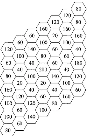
Figure 4.2: Non-uniform traffic distribution pattern 1 with initial arrival rates
The traffic in the cellular network may either follow uniform or non-uniform
distribution. In uniform traffic distribution, every cell has the same traffic load. While in
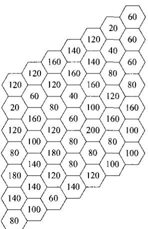
non-uniform traffic distribution, the call arrival rates are different in cells. Two typical
traffic patterns used in [11] are illustrated in Figure 4.2 and Figure 4.3. The number in a
cell represents the mean call arrival rate per hour, under normal load condition. In this
seconds.
Figure 4.3: Non-uniform traffic distribution pattern 2 with initial arrival rates
4.3. Implementation Details
The simulation was implemented in Java programming language using Eclipse 3.2.2
Integrated Development Environment. The platform is SunOS 5.10 with Java Runtime
Environment 1.5. ILOG CPLEX 11.1 is used as the engine for solving ILP problems. This
section describes some details in the simulation.
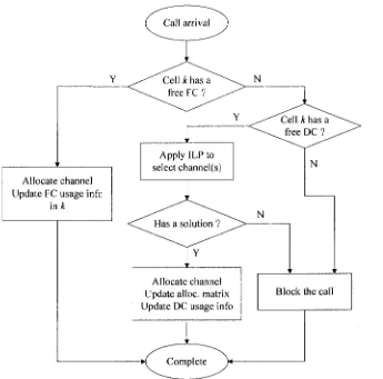
4.3.1. Processing Call Event
generated, in which each record consists of the information about a call, including its ID
number, the cell involved in call arrival, the clock of the time when this call arrival occurs,
and the duration of this call. Obviously, the clock of the time when a specific call is
released can be calculated. Such call arrival and call release are referred to as call events.
Allocate channel Update FC usage info
in k
Apply ILP to
select channel(s) N
N
Allocate channel Update alloc, matrix Update DC usage info
Block the call
Complete
Figure 4.4: Processing call arrival event
All the call events of calls are put together and sorted in terms of the clock of
occurrence, and then processed by the simulator one after another. After processing each
measure the system performance, the numbers of new incoming calls and calls blocked in
the system are recorded. Figure 4.4 shows the flowchart of processing call arrival event,
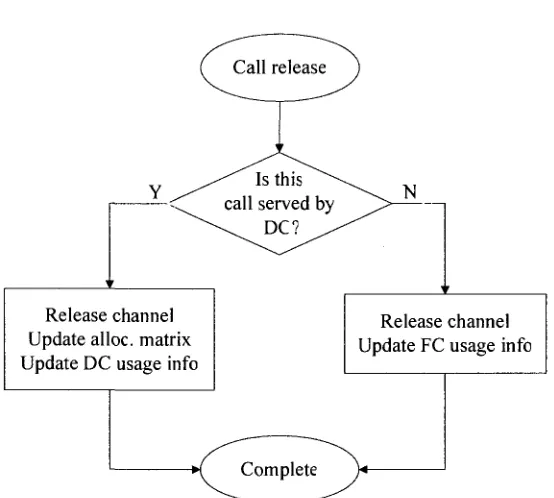
and Figure 4.5 illustrates flowchart of processing call release event.
Release channel Update alloc, matrix Update DC usage info
Release channel Update FC usage info
Complete
Figure 4.5: Processing call release event
4.3.2. Determination of Allocation Matrix
The allocation matrix A is used to record the usage of dynamic channels in the whole
cellular system, hence itself is also dynamic. It is updated every time a call is successfully
assigned a dynamic channel and when an ongoing call is released. Before the start of
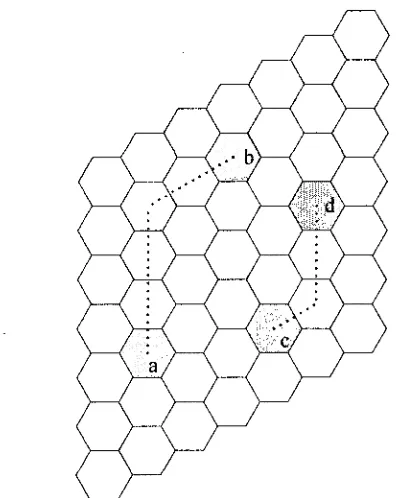
4.3.3. Determination of Distance between Cells
As described in [15], the distance between two cells is a Manhattan distance. The distance
between any two cells is the minimum number of steps needed to move from one cell to
another. A step is the distance between the centers of two adjacent cells, and is considered
as the unit distance. That is, it has value of 1. For instance, as shown in Figure 4.6, the
minimum number of steps required to go from cell a to cell b is 5, so the distance is 5;
while the distance between cell c and J is 3.
Figure 4.6: Distance between two cells
4.3.4. Determination of Link Gain Matrix
radio propagation effects. It depends upon the particular propagation model of the channel
[4]. We herein assume that all link gains are affected by shadow fading only. The signal
strength is assumed to decrease with the second power of the distance. The element, Gy,
of link gain matrix G is given by G, . = , where dy is the distance between the
mobile / and base station/
4.4. Experimental Results
In our simulations, similar to the works in [7], we used three representative ratios of fixed
and dynamic channels, FC:DC: 21:49, 35:35 and 49:21. The performance of the ILP
formulations is derived in terms of blocking probability for new incoming calls.
For formulation ILP1 and ILP2, the initial load in each cell was set to 60% of the
normal load and the results were obtained by increasing the traffic rates by 33% for all
cells. The reuse distance, ro, is set to 3. We also set ^ = 1 . 5 , Wj=1 and fPj=l, which were
determined by trial-and-error. For formulation ILP3 and ILP4, we set r\i, the thermal
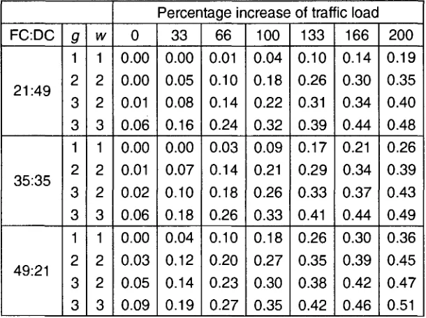
FC:DC 21:49 35:35 49:21 9 1 2 3 3 1 2 3 3 1 2 3 3 w 1 2 2 3 1 2 2 3 1 2 2 3
Percentage increase of traffic load 0 0.00 0.00 0.01 0.06 0.00 0.01 0.02 0.06 0.00 0.03 0.05 0.09 33 0.00 0.05 0.08 0.16 0.00 0.07 0.10 0.18 0.04 0.12 0.14 0.19 66 0.01 0.10 0.14 0.24 0.03 0.14 0.18 0.26 0.10 0.20 0.23 0.27 100 0.04 0.18 0.22 0.32 0.09 0.21 0.26 0.33 0.18 0.27 0.30 0.35 133 0.10 0.26 0.31 0.39 0.17 0.29 0.33 0.41 0.26 0.35 0.38 0.42 166 0.14 0.30 0.34 0.44 0.21 0.34 0.37 0.44 0.30 0.39 0.42 0.46 200 0.19 0.35 0.40 0.48 0.26 0.39 0.43 0.49 0.36 0.45 0.47 0.51
Table 4.1: Blocking probabilities of ILP1
o. 0. £
0-5 o.
.2 o. o S. o. £ o. •i-Ho u -CO 50 45 40 35 30 25 20 15 10 05 00 ] 1
. 1
..'
- a l l
...'.• j.ii i 'M i •„,• 21:49 • 35:35 • 49:21
0 33 66 100 133 166 200
Percentage increase of traffic load
Figure 4.7: Blocking probabilities of ILP2 for g=2 and w=2
Table 4.1 shows the blocking probabilities for channel allocation without any
reassignment of existing calls (obtained using ILP1). As expected, the blocking
channel interval for co-site constraint (g) and adjacent channel constraint (w). But the
network performs better as the number of dynamic channels increases. This was expected
as the higher number of dynamic channels means that the scheme has more freedom and
can choose channels from a larger set to assign to calls.
We have tested ILP2, where channel reassignment is allowed, with different
combinations for the values of g and w, each ranging from 1 to 4. Figure 4.7 shows the
blocking probabilities when g = 2 and w = 2. Results with other values of g and w are
similar. As before, blocking probability increases with traffic, and also with required
channel intervals for co-site and adjacent channel constraints. However, as shown in the
figure, the 21:49 ratio consistently gives the best performance, followed by 35:35 and
49:21.
0.60 £ 0.50
1 1 J= 0.40
o o. 0.30
bo
I 0.20
o o
S 0. 10
0.00
-rfl.rl
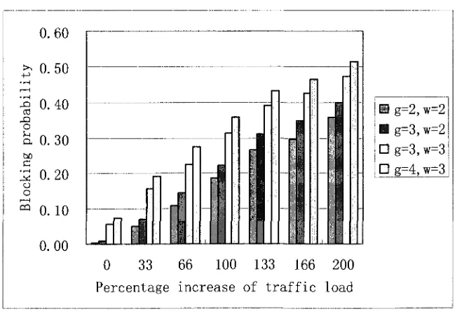
H g=2, w=2 • g=3,w=2 • g=3,w=3 D g=4, w=3
0 33 66 100 133 166 200
Percentage increase of traffic load
Figure 4.8 shows how the blocking probabilities are affected by the requirement of
different values of co-site and adjacent channel intervals, for the ratio 21:49, under
reassignment scheme. We see that even small changes in the values of g and w can have a
significant effect on the blocking probability. The results for the 35:35 and 49:21 ratios
followed a similar pattern, but the overall blocking probabilities were higher.
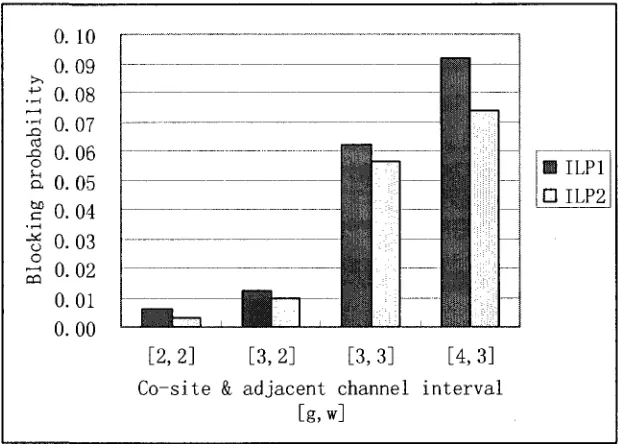
• ILP1 • ILP2
[2,2] [3,2] [3,3] [4,3]
Co-site & adjacent channel interval [g, w]
Figure 4.9: Performances of ILP1 vs. ILP2 for ratio 21:49 with initial traffic load
Figure 4.9 shows the comparison between reassignment and non-reassignment, for
the ratio 21:49 (results with other ratios are similar). Our results indicate that although
channel reassignment does reduce blocking probability, the amount of improvement
seems to vary with traffic load and the values for g and w. We are conducting further
beneficial. FC:DC 21:49 35:35 49:21 Scheme ES ILP1 ES ILP1 ES ILP1
Percentage increase of traffic load
0 0.00 0.00 0.00 0.00 0.00 0.00 20 0.00 0.00 0.00 0.00 0.00 0.01 40 0.01 0.04 0.01 0.03 0.03 0.05 60 0.02 0.06 0.03 0.05 0.05 0.07 80 0.07 0.11 0.08 0.11 0.10 0.12 100 0.14 0.17 0.14 0.16 0.16 0.18 120 0.17 0.19 0.17 0.19 0.19 0.21
Table 4.2: Comparison of performances with ILP1 and the ES approach in [7]
We also have compared our approach with the evolutionary strategy (ES) based
HCA scheme proposed in [7], which considers co-channel constraints only. We simulate
this by setting g = 1 and w = 1 in our formulation. Initial traffic in each cell, percentage
increase of load and other parameters including the values of W; and W2 were set to the
same as in [7]. Table 4.2 compares the results, where the rows "ES" and "ILP1" indicate
the blocking probabilities in [7] and our ILP1, respectively, under different traffic loads.
As shown in this table, our results without channel reassignment are similar to those in [7]
with channel reassignment.
The formulations for HCA integrated with power control, namely ILP3 and ILP4,
0.60 0.50 -2 0-40 O a 0.30 bo
c 0.20
oa 0. 10
0.00
• ILP3
• RD
• FP
0 20 40 60 80 100 120
Percentage increase of traffic load
Figure 4.10: Blocking probabilities of ILP3 for ratio 21:49 with CIR=2
03 •§ o. >-< a. 60 0. C •2 o. o
i — i
aa 0.35 0.30 0.25 20 15 10 0.05
0.00 J |
0 20 40 60 80 100 120
Percentage increase of traffic load
Figure 4.11: Blocking probabilities of ILP3 for ratio 49:21 with CIR=2
Figure 4.10 (and Figure 4.11) compares the blocking probabilities obtained using our
proposed ILP3 with those obtained using a reuse distance based technique (labeled by RD)
[7], and those considering fixed power level (labeled by FP), for the case of FC:DC =
blocking probability, by decreasing co-channel interference at the receivers. The case of
FC:DC = 35:35 follows the same pattern. For above simulations, we set CIR to 2 and
reuse distance to 3. These two parameters can be considered "equivalent" in the sense that
in both cases a single channel can accommodate approximately 8-9 calls simultaneously
in the entire network.
0. 18
0. 16
JO 0 .
CO a c - o cj ,2 o CD 0 0. 14 12 10 08 06 04 02
00 I I 1 —Jiffll
121:49
135:35
149:21
0 20 40 60 80 100 120
Percentage increase of traffic load
Figure 4.12: Comparison of different FC:DC ratios with CIR=2 for ILP3
Figure 4.12 compares the relative performance of the different ratios of FC:DC,
using the proposed ILP3 for CIR=2. As expected, blocking probability increases with
traffic, and the 21:49 ratio consistently gives the best performance, followed by 35:35 and
>,
+ J
• r H •r-4 X ) n o D. hfl c _*: o .—1 m 0.40 0.35 0.30 0.2b 0.20 0. lb 0.10 0.0b
0.00 1 1 i _r i l i
i - i
=
7
1
0 20 40 60 80 100 120
Percentage increase of traffic load
BCIR= HCIR= DCIR= ECIR= =2 =3 -A --8
Figure 4.13: Effect of CIR on blocking probability for ratio 21:49 for ILP3
In addition, we study how the blocking probability is affected by using different
values of CIR. The higher the value of CIR, the better the QoS for the communication.
However, this increase in quality comes at a price. In order to accommodate the higher
CIR value, two calls using the same channel must be separated by a larger distance. This
results in a lower channel utilization and a corresponding increase in blocking probability,
as shown in Figure 4.13.
Finally, we compare ILP3 with ILP4 with same parameters. Figure 4.14 shows the
result for ratio 35:35 with CIR=3. From it we can see that their blocking probabilities are
very close to each other. The situation remains similar when testing for different FC:DC
ratios with different CIR values. We think this is because that, in this scenario, only
co-channel interference is taken into consideration. The improvement of reassignment
channel interference simultaneously. However, more simulations should be conducted to
fully study their properties.
0.25
0.20
1 0.15
o a
o
o 0.05
0.00
BILP3
• ILP4
0 20 40 60 80 100 120
Percentage increase of traffic load
5. Conclusion and Future Work
In this paper we have presented two new sets of integer linear programming formulation
for hybrid channel assignment in wireless cellular networks. The first set does not
consider power control problem, while the second set of formulation is capable of
integrating power control.
For the first series, to the best of our knowledge, this is the first time to optimally
solve the hybrid channel assignment problem that takes into consideration the co-site and
the adjacent channel constraints, in addition to the co-channel constraints. The results
indicate that even without channel reassignment, our approach (with ILP1) produces
results comparable to some existing schemes that perform reassignment. Additional
improvements can be obtained if we allow channel reassignment (with ILP2) as well.
The second set of ILP formulation is aiming the combined channel assignment with
power control. Our approach not only selects an available channel for a new incoming
call, but also determines the appropriate transmission power level for all calls using the
selected channel. The goal is to select a channel such that the total power consumption for
CIRs of all existing calls and the new call are maintained above a specified threshold.
Therefore, unlike many previous approaches, we guarantee that no ongoing calls will be
dropped due to the introduction of the new call. Experimental results show that our
approach leads to a significant reduction in blocking probability, compared to techniques
both CIR based (without power control) and reuse distance based.
For the future work, we will study the CIR based QoS measurement when applied to
Bibliography
[1] G. Chakraborty, "An Efficient Heuristic Algorithm for Channel Assignment
Problem in Cellular Radio Networks", IEEE Transactions on Vehicular
Technology, vol.50, no.6, pp.1528-1539, 2001.
[2] S. Hamouda, S. Tabbane and P. Godlewski, "Improved Reuse Partitioning and
Power Control for Downlink Multi-cell OFDMA Systems", Proceedings of the
2006 workshop on Broadband Wireless Access for Ubiquitous Networking, 2006.
[3] W.K. Hale, "Frequency Assignment: Theory And Applications", Proc. IEEE,
vol.68, no.12, pp. 1497-1514, 1980.
[4] N. Bambos, S. C. Chen and G J. Pottie, "Channel Access Algorithms with Active
Link Protection for Wireless Communication Networks with Power Control",
IEEE/ACM Transactions on Networking, vol.8, no.5, pp.583-597, 2000.
[5] D. Ayyagari and A. Ephremides, "Power Control for Link Quality Protection in
Cellular DS-CDMA Networks with Integrated (Packet and Circuit) Services",
[6] T. Farid, A. Ngom and A. Jaekel, "Integrated Hybrid Channel Assignment and
Distributed Power Control in Wireless Cellular Networks using Evolution
Strategy", IEEE Symposium on Computational Intelligence in Image and Signal
Processing, pp. 293-300, 2007.
[7] G. Vidyarthi, A. Ngom and I. Stojmenovic, "A Hybrid Channel Assignment
Approach using an Efficient Evolutionary Strategy in Wireless Mobile Networks",
IEEE Transactions on Vehicular Technology, vol. 55, no.5, pp. 1887-1895, 2005.
[8] S. Ni. "Distributed Channel Allocation Algorithm with Power Control", In the 8th
IEEE International Symposium on Personal, Indoor and Mobile Radio
Communications (PIMRC), Volume: 2, pp. 406 - 410, 1997.
[9] C. N. Chuah, R. D. Yates and D. J. Goodman, "Integrated Dynamic Radio
Resource Management", In Vehicular Technology Conference, Volume 2 pp. 584
-588, 1995.
[10] A. Lozano and D. C. Cox, "Integrated Dynamic Channel Assignment and Power
Control in TDMA Mobile Wireless Communication Systems", IEEE Journal on
Selected Areas in Communications, Volume 17 (11), pp. 2031 - 2040 , 1999.
[11] H.G. Sandalidis, P. Stavroulakis and J. Rodriguez-Tellez, "An Efficient
Systems", IEEE Transactions on Evolutionary Computation, vol.2, no.4,
pp.125-137, 1998.
[12] X. Wu, A. Jaekel, A. Bari and A. Ngom, "Optimized Hybrid Resource Allocation
in Wireless Cellular Networks with and without Channel Reassignment",
IEEE/ComSoc International Conference on Information Technology: New
Generations, 2009.
[13] R. C. V Macario, "Cellular Radio: Principles and Design, 2nd Ed.", New York:
Macmillan, 1997.
[14] A. Hac, "Cellular Network Model with Hand off Delays", in Proc. IEEE Int. Conf
Communications ICC, pp. 1834-1838, 1995
[15] G. Vidyarthi, "Integrated Channel Assignment and Power Control in Wireless
Mobile Network using Evolutionary Strategy", MSc. Thesis, University of Windsor,
2003.
[16] W. C. Y. Lee, "Mobile Communications Design Fundamentals", Wiley, 1993.
[17] G. Vidyarthi, A. Ngom and I. Stojmenovic, "Evolutionary Methods in Wireless
Mobile Computing", In "Combinatorial Optimization in Communication