A CAN Protocol Based Hybrid
Communication to Avoid Collision of Vehicles
Prof. S. S. Lavhate1, Sagar D. Devagire 2
Associate Professor, Pravara Rural Engineering College, Savitribai Phule Pune University, Pune, India1
P. G. Student, Department of Electronics & Telecommunication, Pravara Rural Engineering College, Savitribai Phule
Pune University, Pune, India2
ABSTRACT:In today's reality where science has made stunning advances so have the late vehicles. These vehicles are more cutting-edge than any other time in recent memory. They have more speed, cutting edge motors and are excessive because of these reasons there is a need to adjust a gadget which can constantly screen all the different parameters of auto. So the utilizing CAN transport (Controller Area Network) which is broadly utilized as a part of various fields of industry and specific in the auto business, which permit the investigation of information going through the transport and era of messages. In this way the utilizing CAN transport outlining two diverse correspondence (entomb or intra) which is inside the vehicle and in the middle of vehicles. For correspondence reason here planning such a framework where vehicle drivers communicate with each other through the ZigBee correspondence furthermore through IR transmitter-collector vehicles can demonstrate to each other. Likewise planning such a framework which in the event of mishap will record every one of the parameters furthermore keep any mischances to happen and which will astutely make hesitant move to stay away from any mishaps before happen. In this framework the GPS and different sensors connected to the Car, will give all vehicle data straight forwardly to the proprietor. In this way fruitful execution of vehicle framework having all aforementioned application will be useful for shirking of impact in the middle of vehicles.
KEYWORDS:Accelerometer, fog indication system, rear-end collision, IR communication, ZigBee, collision warning and avoidance system.
I. INTRODUCTION
and the multifaceted nature between the ECUs. Be that as it may, the multiplexed correspondence has not met the continuous correspondence prerequisites[7].
In 1980s, BOSCH, an innovation based enterprise planned a multi expert serial correspondence convention called Controller Area Network (CAN) which is strong, continuous furthermore diminishes the measure of links to be utilized for the interconnections. The CAN convention is an offbeat serial correspondence convention which takes after ISO 11898 models and is generally acknowledged in cars because of its constant execution, unwavering quality and similarity with extensive variety of gadgets. The CAN convention is a two wire, half duplex framework which has information rates up to 1Mbps and offers an abnormal state of security. Its convenience, strong, minimal effort and flexible innovation made it pertinent in different ranges of utilizations where entomb processor correspondence or disposal of extreme wiring is required. A percentage of the regions it is generally utilized are modern hardware, aeronautics, therapeutic equipment's, building mechanization and so forth [11].
The remainder of this paper is organized as follows. In Section II, described the objective of this paper. In section III we discussed about existing work and systems at the beginning of each section, we define the problem and its levels of difficulties, and then classify the existing algorithms with our discussion and in Section IV demonstrate scheme of implementation of proposed system. In Section V, explaining in detail how system works and its workflow and in section VI explaining actual proposed system with description. In section VII summarize this paper and discuss applications, areas for future research and conclusion.
II. RELATED WORK
According to a report presented by National Institute of Disaster Management, in India at regular intervals there is a street mishap i.e. l080 mishaps every day. Human blunders add up to 93 % of all mischances and as indicated by police, backside crash, passing the main vehicle and not understanding about right or left side moving vehicle constitute 80% of every deadly mishap [1]. A mischance in which the back of a vehicle is hit by a trailing auto, because of quick change in auto's velocity as a consequence of crisis or hard brake connected is termed as backside crash. STRADA (Swedish Traffic Accident Data Acquisition) performed an examination that shows 9l% of all backside impacts and overwhelm crash include trucks [5]. The most widely recognized backside impact and passing the main vehicle is a crash where an auto's back is slammed by an overwhelming truck.
Likewise more impacts that include backside crash do happen visible to everyone with great perceivability conditions on a straight street and in great climate condition however in any case terrible climate or awful perceivability could likewise prompt backside impact. Decreasing auto collisions is one of the fundamental destinations of any transportation framework. Mishaps because of backside impacts and surpass driving vehicle is exceptionally normal and it becomes one of the exploration wailed subject in the car segment [7]. As the Driver's capacity to keep consideration has a key part to play in anticipation of such impacts, a computerized framework that helps the driver would end up being of awesome help in lessening these mischances altogether [8].
The late innovation patterns in the car business are incorporating so as to acquire more solace a vehicle mechanization methods like crash evasion (which utilizes lasers to distinguish the items around the vehicle and when the vehicle gets closer to any question, the brakes will be connected consequently), propelled wellbeing highlights, amusement gadgets and part more [7]. As the innovation is building up, the utilization of electronic control units (ECU) in vehicles is expanding quickly, making the correspondence between them exceptionally intricate. Multiplexed correspondence was in the end created to diminish the interconnections (links) and the intricacy between the ECUs. Yet, the multiplexed correspondence has not met the ongoing correspondence necessities. In 1980s, BOSCH, an innovation based organization composed a multi expert serial correspondence convention called Controller Area Network (CAN) which is hearty, continuous furthermore diminishes the measure of links to be utilized for the interconnections [8].
required. A portion of the zones it is broadly utilized are modern apparatus, aeronautics, therapeutic equipment's, building mechanization and so forth [1].
Our system aims at the automatic detection of text. This is done by the algorithm. Fig. 1 shows the flow diagram of text detection algorithm. The algorithm steps are summarized as follows.
III.OBJECTIVE
To design and implement:
1. Rear-end collision avoidance system.
2. Steering moving (right or left) indication system.
3. If fog is in front of vehicle, smoke sensor sense that fog and vehicles red headlight beam will glow automatically.
4. Safely overtake/pass the leading vehicle.
5. System where all vehicle information or all parameters of the vehicle directly show to the owner.
IV.SCHEME OF IMPLEMENTATION
In this section block diagram of system is presented. A two vehicle are used for demonstration of system hence block diagram of first vehicle is shown in Fig. 1 (a) whereas block diagram of second vehicle is shown in Fig 1 (b).
V.
Fig. 1 Scheme of system implements in vehicle (a) First vehicle system implantation (b) Second vehicle scheme of implementation
V. SCHEME OF IMPLEMENTATION
The proposed system uses an ARM 7 processor which is known for its efficient control and response time. The system is quick in response when compared with the available GPS and GSM based system in terms of response time. It is independent of any external infrastructure and network to calculate all its parameters which again increase efficiency. It is lower in cost as all its component are cheaply available and the processor is known for its cost effectiveness among its peer processors.
The LPC2119/LPC2129 are based on a 16/32 bit ARM7TDMI-S™ CPU with real-time emulation and embedded trace support, together with 128/256 kilobytes (kB) of embedded high speed flash memory. A 128-bit wide memory interface and a unique accelerator architecture enable 32-bit code execution at maximum clock rate. For critical code size applications, the alternative 16-bit Thumb® Mode reduces code by more than 30 % with minimal performance penalty.
A. REAR-END COLLISION AVOIDANCE SYSTEM.
Here in this system, Transmitter and Receiver: The IR transmission uses pulse width modulation to communicate the breaking intensity. This signal is nothing but rectangular pulses with frequency around 40Khz. The detected signal can be measured for the change in frequency to measure the distance between the two vehicles. The concept of Doppler Effect is used to measure the distance; basically the number of Pulses can be counted in specified duration of time. The change in number of Pulse will be proportion to the distance the signal travels. When it detect the signal from front vehicle it transmits information to ARM LPC 2129 and it take action like if dc motor (vehicle) speed is high and close to front side vehicle, then stops it directly otherwise if speed is less and close to front side vehicle, then it get displayed on lcd and indicated by buzzer for keep distance from front side vehicle.
The IR Receiver side input triggers the timer Circuit of microcontroller to count the number of pulse in of fixed duration of time T. The value of number of Pulses in time period is compared with the value obtained at the frequency used for transmission which is fixed. The distance is estimated by the time obtained from different of the above number of pulses. The distance velocity of care is used to calculate the time Gap. Time gap is less than the set point then the
speed of vehicle is decrease. And it also check the distance between two vehicle to take evasive action for rear end collision of vehicle.
Fig. 2 (a) IR communication for CAS (b) On vehicle IR detection
1) Time gap calculation:The IR transmission uses pulse width modulation to communicate the breaking intensity. This signal is nothing but rectangular pulses with frequency around 40 khz. The detected signal can be measured for the change in frequency to measure the distance between the two vehicles. The concept of Doppler Effect is used to measure the distance. Basically the no. of pulses can counted in specified duration of time. The change in number of pulses will be proportional to the distance the signal travels in fig. 3.
Fig. 3 Spread in pulse width proportional to the distance
2) Control system: The IR receiver input triggers the timer circuit of microcontroller to count the number of pulses in fixed duration of time T. The value of number of pulses in time period is compared with the value obtained at the frequency used for transmission which is fixed. The distance is estimated by the time obtained from difference of the above number of pulses. The distance and velocity of car is used to calculate the Time Gap (TG).
TG =
Fig. 4 Vehicle detection in percentage
VI.STEERING MOVING (RIGHT OR LEFT) INDICATION SYSTEM
Here in this system, Accelerometer is directly connected to the steering. It is an electro-mechanical which measures static and dynamic acceleration due to moving of the vehicle measured in terms of g force.
Fig. 5 (a) ADXL335 Accelerometer (b) Block diagram of vehicle indication system
At night, If driver moving the steering right side then led light moving towards the right side. And also steering moving left side then led light moving towards the left side. Because of that the vision of driver at night is wide at corner of right and left so condition of accident will be less.
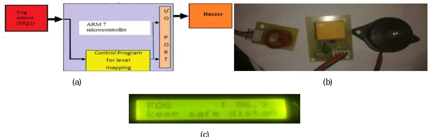
VII. FOG CONDITION
In weather condition, If fog is detected in front of vehicle, smoke sensor sense that fog and vehicles red head light beam will be glow automatically. Therefore condition of accident will be less.
Fig. 6 (a) Block diagram of fog indication (b) Fog sensor with buzzer (c) Fog indication on vehicle display
VIII. SAFELY OVERTAKE/PASS THE LEADING VEHICLE
We are designing a mechanism of 3 LEDs (red - no pass, green-pass, yellow-to ask pass) and 3 keys to manage the overtake between two vehicles will be easy, condition of accidents will be less if driver know the exact position of the vehicle in front of other vehicle.
(a) (b)
(a) (b)
Fig. 7 (a) Block diagram of zigbee communication (b) Keys and LED for safely overtake the leading vehicle
Here if driver wants to overtake the vehicle of front, than back vehicle driver request to press 3rd key to glow yellow light than front driver, if he wants to give pass than press 2nd key to glow green light and back driver easily pass. If any accidental condition is their so front driver not giving any pass to indicate to the back driver than press 1st key to glow red light so back driver know the danger. So never pass. This communication between two vehicles will be done by zigbee communication.
IX.SYSTEM WHERE ALL VEHICLE INFORMATION OR ALL PARAMETERS OF THE VEHICLE
DIRECTLY SHOW TO THE OWNER
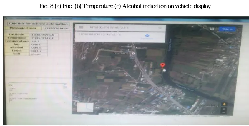
Here in this system two different vehicles of intra communication are connected to the server through GSM. Here particular vehicle send respective information i.e Fuel is less or high, Engine temperature, If Driver consume high or low alcohol level, if driver not wearing seat belt etc… these information are send from uC through GSM and receiver side another GSM will be received and through GUI displayed all information in Visual Basic software.
Fig. 8 (a) Fuel (b) Temperature (c) Alcohol indication on vehicle display
Fig. 9 Vehicle display all parameter and GPS position
(a) (b)
Fig. 10 Flowchart diagram (a) First vehicle working flowchart diagram (b) Second vehicle flowchart diagram
X. APPLICATIONS, CONCLUSION AND FUTURE SCOPE
A. APPLICATIONS
1. MEDICALE (Ambulance)
2. ARMY (Tank Trucks)
3. NEAVY (Ships)
4. INDUSTRIES (Automatic Robots, Crane)
5. PUBLIC TRANSPORT (Car, Bus, Train, Aero plane)
B. CONCLUSION AND FUTURE SCOPE RESEARCH
In the undertaking, framework will be incorporated with CAN controller for compelling control of impact of parameter and other control activity in shirking of crash. So utilizing CAN planning such a framework which if there should arise an occurrence of mishap will record every one of the parameters furthermore keep any mischances to happen and which will insightfully make sly move to maintain a strategic distance from any mishaps before happen. Thus the using CAS and CWS system we make also side vehicle collision avoidance system. Subsequently the framework will be actualized with applications like directing moving (right or left) sign framework, vehicle sign framework in haze, backside crash evasion framework, securely surpass or pass the main vehicle framework. Thus successful implementation of vehicle system having all above mentioned application will be helpful for collision avoidance in between vehicles.
REFERENCES
[1] MaziarNekovee, “Quantifying Performance Requirements of Vehicle-to-Vehicle Communication Protocols for Rear-end Collision Avoidance”, IEEE 69th, Vehicular Technology Conference, 2009. VTC Spring 2009,page no. 1-5, 2009 IEEE.
[2] Takeshi Kasuga, Satoshi Yakubo, “Design of a Highly Safe Model Vehicle for Rear-End Collision Avoidance Considering Multiple Faults of Sensors”, International Conference on Computational Intelligence, Modelling and Simulation, page no. 63-68,2009 IEEE
[3] Ding Shiqing, Song Yandong, Ding Jibin, “The Research for Mechanism of Vehicle Rear end Collision Avoidance System”, International Conference on Intelligent Computation Technology and Automation, page no. 889-892, 2010 IEEE
[4] A. Farahani , G. Latif-Shabgahi, F.Tajarrod, “On the Priority Problem of CAN Protocol: A New Idea”, Education Technology and Computer (ICETC), 2010 2nd International Conference on, page no. V2.500-V2.505, 2010 IEEE
[5] Huang Zhu, Gurdip Singh, “A Communication Protocol for a Vehicle Collision Warning System”, IEEE/ACM International Conference on Green Computing and Communications & 2010 IEEE/ACM International Conference on Cyber, Physical and Social Computing, Pages: 636 – 644, 2010 IEEE
[6] Meng Chen, Fasheng Liu, ChuanxiangRen, ZhiminGao, “A Control System of Vehicle Rear-end Anti-collision”, Intelligent Human-Machine Systems and Cybernetics (IHMSC), 2012 4th International Conference on, Pages: 46 – 48, 2012 IEEE
[7] Adrian Cabrera, Sven Gowal and AlcherioMartinoli, “A New Collision Warning System for Lead Vehicles in Rear-end Collisions”, Intelligent Vehicles Symposium (IV), 2012 IEEE, Pages: 674 – 679, 2012 IEEE
[8] Liang Li, Guangquan Lu, Yunpeng Wang, DaxinTian, “A Rear-end Collision Avoidance System of Connected Vehicles”, IEEE 17th International Conference on Intelligent Transportation Systems, Pages: 63 – 68, 2014 IEEE
[9] Der-CherngLIaw, Cheng-Yu Yu an d Kuo-Chen Wu, “A CAN-Based Design for the Control of Electric Vehicle”, 14th International Conference on Control, Automation and Systems, Pages: 1233 – 1237, 2014.
[10] Ashutosh U. Jadhav, N.M. Wagdarikar, “A Review: Control Area Network (CAN) based Intel-ligent Vehicle System for Driver Assistance using Advanced RISC Machines (ARM)”,2015 International Conference on Pervasive Computing, Pages: 1 – 3, 2015 IEEE.
[11] PradhanSuvenduKedareswar, Venkata Subramanian Krishna moorthy, “A CAN Protocol Based Embedded System to Avoid Rear-End Collision of Vehicles”, Pages: 1 –5, 2015 IEEE
[12] Global Status Report On Road Safety 2013: Supporting A Decade Of Action,” World Health Organization (Who), Geneva, Switzerland, 2013. [13] “Global Status Report On Road Safety: Time For Action,” World Health Organization (Who), Geneva, Switzerland, 2009.
[14] “Decade Of Action For Road Safety 2011–2020: Global Launch,” World Health Organization (Who), Geneva, Switzerland. [Online]. [15] D. Mohan, “Analysis Of Road Traffic Fatality Data For Asia,” J. Eastern Asia Soc. Trans. Stud., Vol. 9, Pp. 1786–1795, 2011.
[16] S. Zehang, G. Bebis, And R. Miller, “On-Road Vehicle Detection: A Review,” Ieee Trans. Pattern Anal. Mach. Intell., Vol. 28, No. 5, Pp. 694–711, May 2006.
[18] S. Zehang, G. Bebis, And R. Miller, “Monocular Precrash Vehicle Detection: Features And Classifiers,” Ieee Trans. Image Process., Vol. 15, No. 7, Pp. 2019–2034, Jul. 2006.
[19] H.-J. Cho And M.-T. Tseng, “A Support Vector Machine Approach To Cmos-Based Radar Signal Processing For Vehicle Classification And Speed Estimation,” Math. Comput. Modelling, Vol. 58, No. 1/2, Pp. 438–448, Jul. 2012.
[20] F. Nashashibi And A. Bargeton, “Laser-Based Vehicles Tracking And Classification Using Occlusion Reasoning And Confidence Estimation,” In Proc. IeeeIntell. Veh. Symp., 2008, Pp. 847–852.
[21] D. J. Natale, R. L. Tutwiler, M. S. Baran, And J. R. Durkin, “Using Full Motion 3d Flash Lidar Video For Target Detection, Segmentation, And Tracking,” In Proc. IeeeSsiai, 2010, Pp. 21–24.
[22] S. Xuan, Z. Zheng, Z. Chenglin, And Z. Weixia, “A Compressed Sensing Radar Detection Scheme For Closing Vehicle Detection,” In Proc. IeeeIcc, 2012, Pp. 6371–6375.
[23] S. J. Park, T. Y. Kim, S. M. Kang, And K. H. Koo, “A Novel Signal Processing Technique For Vehicle Detection Radar,” In Proc. IeeeMtt-S Int. Microw. Symp. Dig., 2003, Pp. 607–610, Vol. 1.
[24] R. Sen, P. Siriah, And B. Raman, “Road Sound Sense: Acoustic Sensing Based Road Congestion Monitoring In Developing Regions,” In Proc. 8th Annu. IeeeCommun. Soc. Conf. Secon, 2011, Pp. 125–133.
[25] M. Mizumachi, A. Kaminuma, N. Ono, And S. Ando, “Robust Sensing Of Approaching Vehicles Relying On Acoustic Cues,” Sensors, Vol. 14, No. 6, Pp. 9546–9561, May 2014.
[26] K. Jisu, H. Sungjun, B. Jeonghyun, K. Euntai, And L. Heejin, “Autonomous Vehicle Detection System Using Visible And Infrared Camera,” In Proc. 12th Iccas, 2012, Pp. 630–634.
[27] C. Stiller, J. Hipp, C. Rössig, And A. Ewald, “Multisensor Obstacle Detection And Tracking,” Image Vis. Comput., Vol. 18, No. 5, Pp. 389– 396, Apr. 2000.
[28] R. Chellappa, Q. Gang, And Z. Qinfen, “Vehicle Detection And Tracking Using Acoustic And Video Sensors,” In Proc. IeeeIcassp, 2004, Vol. 3, Pp. Iii-793-1–Iii-793-6.
[29] C. Blanc, L. Trassoudaine, And J. Gallice, “Ekf And Particle Filter Trackto- Track Fusion: A Quantitative Comparison From Radar/Lidar Obstacle Tracks,” In Proc. 8th Int. Conf. Inf. Fusion, 2005.
[30] G.F. Ross, H.M. CronsonAnd B. Rama Raob “A New Collision Avoidance System Using Baseband Reflectometry,” 1978.
[31] Clovis R. Haden “A Student-Designed Automotive Collision Avoidance System,” Ieee Transactions On Vehicular Technology, Vol. Vt-27, No. 1, February 1978.
[32] Andreas Eidehall, Jochen Pohl “Toward Autonomous Collision Avoidance By Steering,” Ieee Transactions On Intelligent Transportation Systems, Vol. 8, No. 1, March 2007.