Z-Source Inverter: A Comparative Analysis
Navdeep Singh1
J.E/Electrical400 kV S/S, PSTCL, Sri Muktsar Sahib, Punjab, India1
ABSTRACT:A Z-source inverter is a sort of force inverter, a circuit that proselytes direct current to exchanging current. It capacities as a buck-support inverter without making utilization of DC-DC converter span because of its one of a kind circuit topology. Maximum power point technique is used to track the maximum power point. There are many MPPT techniques to boost the voltage introduced in this paper.
KEYWORDS:Z-Source Inverter, Semiconductor Switches.
I.INTRODUCTION
The power electronic literature centres the level and attributes of the source voltage have been changed utilizing distinctive converter topologies. Every converter topology has its own limitations in regards to various angles like a number of segments utilized, weight on semiconductor switches and converter productivity. Some of these converters have discovered spots in industry for an assortment of utilizations.
Today efficient power conversion is more critical than before as a result of the option vitality sources like power devices, sunlight based vitality, wind vitality and sea wave vitality that require appropriate force molding to adjust to various burdens. Additionally, hybrid vehicles are extremely encouraging new uses of force converters. Additionally, the zone of electrical drives is as yet requesting for new topologies keeping in mind the end goal to discover more effective and less expensive methods for changing the type of vitality from electrical to mechanical or the other way around. Since spotless, solid and excellent vitality is one of the fundamental worries in today's reality, power hardware will assume an imperative part in filling this hole. Power electronics has been broadly utilized as a part of different applications since it was conceived. The single stage inverter, which changes over dc voltage/current into single stage AC voltage/current is one of its most essential and famous converters. It has been broadly utilized as a part of uninterruptible force supplies (UPS) , utilized as a part of AC motor control , grid-connected PV framework . There are two sorts of conventional inverters, in particular, voltage source inverter and current source inverter. Be that as it may, both inverters have some theoretical hindrances, in this manner; Z-source inverter is presented..
II.Z SOURCE INVERTER
The Z-source converter (ZSC) is an option power transformation topology that can both buck and help the data voltage utilizing detached parts. It utilizes an extraordinary LC impedance system for coupling the converter principle circuit to the force source, which gives a method for boosting the data voltage, a condition that can't be gotten in the conventional inverters. It likewise permits the utilization of the shoot-through exchanging state, which disposes of the requirement for dead-times that are utilized as a part of the customary inverters to dodge the danger of harming the inverter circuit. The modeling & simulation of a solitary stage Z-source inverter and its control techniques for usage dc-to AC power change is introduced. The outline of Z-system and a single stage full bridge inverter modeling and simulation is conveyed in MATLAB-Simulink environment. A fixed DC input voltage is given to the inverter and a controlled AC yield voltage is gotten by variable duty cycle or modifying the on and off times of the inverter parts. The duty cycle variation can be accomplished by utilizing pulse width adjustment (PWM) control techniques. The ripple of Z-source component, yield voltage, current and their harmonics profile are controlled with the variation of modulation index and switching frequency. Likewise, the impact of shoot through the state on the conventional inverter is eliminated of in the Z-source inverter. Correspondingly one application is displayed for verification of the modelling & simulation system of photovoltaic (PV) framework in view of Z-Source inverter
Fig 1 : Conventional Z source inverter
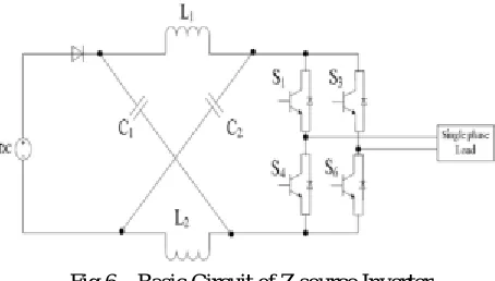
Switches used in the converter can be a combination of switching devices and anti-parallel diode as shown in Fig. 3.3. Six switches are used in the circuit; each is traditionally composed of a power transistor and an anti-parallel (or freewheeling) diode to provide bidirectional current flow and unidirectional voltage blocking capability.
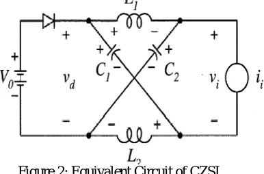
III. EQUIVALENT CIRCUIT
The novel element of the Z-source inverter is that the yield AC voltage can be any worth somewhere around zero and boundlessness paying little heed to the information DC voltage. That is, the Z-source inverter is a buck–boost inverter that has an extensive variety of possible voltage. The customary V-and I-source inverters can't give such component. The primary element of the Z-source is executed by giving entryway beats including the shoot-through heartbeats. Amid the shoot-through state, the yield terminals of the inverter are shorted and the yield voltage to the heap is zero. The yield voltage of the shoot through state is zero, which is the same as the conventional zero states, in this manner the obligation proportion of the dynamic states must be kept up to yield a sinusoidal voltage, which implies shoot-through just replaces a few or the greater part of the customary zero states
Figure 2: Equivalent Circuit of CZSI
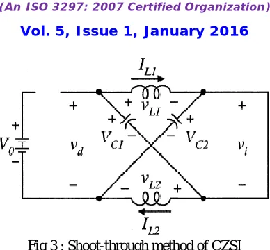
Fig 3 : Shoot-through method of CZSI
A)Inductor. In this mode, isolating the dc connection is from the air conditioner line. This shoot-through mode is to be utilized as a part of each exchanging cycle amid the customary zero vector period created by the PWM control. Contingent upon how much a voltage help is required, the shoot-through interim or its obligation cycle is resolved.
The reason for the inductor is to constrain the present swell through the gadgets amid help mode with shoot through a state. Amid shoot through mode, the reason for the inductors is to restrain the present swell through the gadgets. Essentially the inductor current increments directly and the voltage over the inductor is equivalent to the voltage crosswise over the capacitor.
Fig 4: Non Shoot-through mode of CZSI
The inverter bridge is operating in one of the two traditional zero vectors and shorting through either the upper or lower three device, thus acting as an open circuit viewed from the Z-source circuit. Again, under this mode, the inductor carry current, which contributes to the line current’s harmonic reduction.
IV.ANALYSIS OF IMPEDANCE NETWORK
Assuming that the two inductors (L1 and L2) have the same inductance (L) and two capacitors (C1 and C2) have the same capacitance.
From symmetrical circuit, the voltage across capacitors and inductors become:
V = V = V V = V = V
Now, consider the non-shoot-through state. From Fig. 5, the voltage equations can be obtained as follows:
V = V −V
V = V −V = 2V −V
Now, consider the shoot-through state. From Fig. 6, the voltage equations can be obtained as follows:
V = 0
The peak inverter-bridge voltage of ZSI can be expressed as:
V = BV = V
Where
Vi – is the input voltage.
Vdc – is the DC bus voltage across the inverter bridge, when it is not short.
D – is the duty cycle of short through time interval. B – is the voltage boost factor.
B =
Boost factor is determined by the shoot-through time interval over a switching cycle or the shoot-through duty ratio.
The voltage of capacitor C1 and C2 voltage is related to the input voltage by:
V = V
The voltage gain is defined as: Shorter shoot through duty ratio is used to generate the same ac output voltage.
G = MB =
The maximum voltage gain is expressed as:
G = MB = (1−D)
The required shoot-through duty ratio (T0/T) is expressed as:
D = ORD =
The voltage stress on Z-source capacitor and inverter-bridge of the ZSI, respectively, are determined as:
V = GV
V = (2G−1)V
The peak phase ac output voltage can be expressed as
V = M = MB
Where:
M - Modulation index
Vac - Peak value of the ac output phase voltage. B - Boost Factor
The boost factor B is determined by the modulation index M. The boost factor B can be controlled by duty cycle of the shoot-through zero state over the non-shoot through states of the PWM inverter. The shoot-through zero state does not affect PWM control of the inverter. Because, it equivalently produces the same zero voltage to the load terminal, the available shoot- through period is limited by the modulation index.
The modulation index also called as amplitude modulation ratio (M) which is the main control factor is defined as the ratio of amplitude of reference wave to the amplitude of carrier wave.
M =
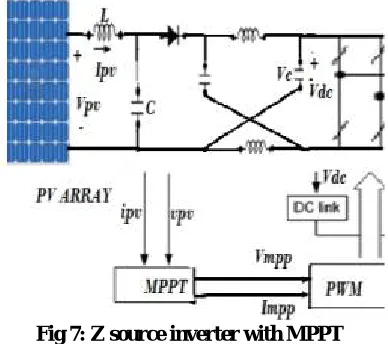
B)Z source inverter with PV panel : The produced power from Photovoltaic (PV) frameworks is in the structure DC (Direct Current). PV-associated inverters are fundamental for DC - AC transformation. For change of dc-ac in framework associated PV framework, there are a few sorts of topologies and inverter outlines are utilized as a part of existing establishments. Z-Source inverter is one of them. Unwavering quality, life range, and support needs ought to be ensured through long haul operation of a PV framework. Further diminishments of cost, size and weight are required for the PV frameworks.
Fig 5: Equivalent circuit of PV cell
Principle : The yield voltage waveform of the inverter can be square wave, semi square wave or low twisted sine wave. The yield voltage can be controlled (i.e. movable) with the assistance of drives of the switches. The Pulse width Modulation (PWM) systems are most usually used to control the yield voltage of inverters. Such inverters are called PWM inverters
Z source inverter operated with the combination of VSI(Voltage Source Inverter) and the CSI(Current Source Inverter). Normally the traditional inverters convert the DC voltage in to AC voltage.
Fig 6 – Basic Circuit of Z source Inverter
each of the three stage legs. The Z-source system makes the shoot-through zero state and non-shoot through exchanging state is conceivable. This shoot-through zero state gives the interesting buck-help highlight to the inverter.
C) Inductor choice
Amid conventional operation mode, when there is no shoot-through, the capacitor voltage is constantly equivalent to the information voltage; along these lines, there is no voltage over the inductor and just an unadulterated dc current experiencing the inductors. The motivation behind the inductor is to restrain the present swell through the gadgets amid support mode with shoot-through. The normal current through the inductor is
Amid shoot-however, the inductor current increments directly, and the voltage over the inductor is equivalent to the voltage over the capacitor; amid non-shoot-through modes (six dynamic modes and the two customary zero modes), the inductor current reductions sprightly and the voltage over the inductor is the distinction between the information voltage and the capacitor voltage.
1 2 c
L
L
fV
D) Capacitor Selection
The reason for the capacitor is to retain the present swell and keep up a genuinely steady voltage in order to keep the yield voltage sinusoidal. Amid shoot-through, the capacitor charges the inductors, and the current through the capacitor rises to the current through the inductor. In this manner, the voltage swell over the capacitor can be generally ascertained by
1 2 av
C
C
I f
V. Z SOURCE INVERTER WITH PERTURB & OBSERVE CONTROLLER WITH PV FED
The output power of the sunlight based PV module alters with change in course of the sun, change in sun oriented insolation level what's more, change in temperature. Additionally there is a maximum power point in the PV attributes of the PV module for a specific working condition. It is coveted that the PV module works near this point, i.e., yield of the PV module approaches close to MPP. The procedure of working PV module at this condition is called as maximum power point technique (MPPT). Maximisation of PV force enhances the usage of the sun oriented PV module.[11] Many MPPT calculationshad been proposed before. Incrementalconductance &Perturb Observe method is mainly used.
Fig 7: Z source inverter with MPPT
frequently used MPPT method as a result of its straightforwardness of usage. Bother and Observe strategy may achieve top-level profitability, gave that a suitable judicious and adaptable slant climbing technique is grasped
Daylight based cells have a many-sided relationship amidst temperature and full scale resistance that makes a non-direct yield capability which can be inspected in light of the I-V bend. It is the inspiration driving the MPPT structure to test the yield of the PV cells and apply the most ideal resistance (weight) to secure most great power for any given biological conditions. MPPT gadgets are regularly organized into an electric power converter structure that gives voltage or current change, isolating, and control for driving distinctive burdens, including power networks, batteries, or motors.
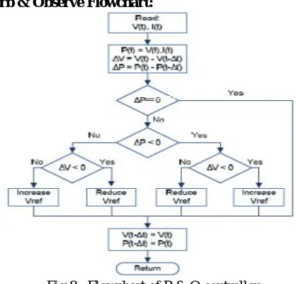
Perturb & Observe Flowchart:
Fig 8 : Flowchart of P & O controller
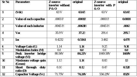
Sr No Parameters Z-source inverter without P & O
original Z-source inverter with P & O
original
1 (Vdc) 63 V 63.65 63 V 63.65
2 Value of each capacitor .0003 F .0001F .0003 F 0.0001
3 Value of each inductor .0045 H .0063H .0045 H .0063
4 Vac 35.9 V 37.23 291.6 295.7
5 Iac 0.4232 0.5161 3.462 4.078
6 Voltage Gain (G) 1.14 1.16 9.25 9.30 7 Modulation Index (M) 0.6 0.8 0.6 0.8 9 Peak inverter bridge
voltage (Vi)
80.56V 84.21V 1049.58V 1600V
10 Maximum voltage gain (Gmax)
1.13 1.16 8.83 13
11 Shoot through duty ratio (D)
0.10 0.12 0.47 0.528
12 Capacitor Voltage (Vc) 71.75V 74.24V 556.29V 832V
Table 1:
VI. CONCLUSION
PV cells is the efficient method to produce power. MPPT techniques can increase the voltage by extracting the maximum point. P & O method is simplest & cheapest of all other MPPT techniques. We can boost the voltage by changing various parameters like modulation index, capacitance, inductance & switching devices. So anew model can be formed with this.
.
REFERENCES
1. Fang Luo ,Peng wei Xu , Yong Kang , Shang xu Duan, “A Variable Step Maximum Power Point Tracking Method Using Differential Equation Solution”, Second IEEE Conference on Industrial Electronics and Applications,2007.
2. Jong-Hyoung Park, Heung-Geun Kim, Eui-Cheo Nho, Tae-Won Chun, Jaeho Choi, “Grid-connected PV System Using a Quasi-Z-source Inverter” IEEE,2009.
3. Quoc-Nam Trinh* and Hong-Hee Lee, “A New Z-Source Inverter Topology with High Voltage Boost Ability” Journal of Electrical Engineering & Technology Vol. 7, No. 5, pp. 714~723, 2012.
4. SURESH L., G.R.S. NAGA KUMAR, and M.V. SUDARSAN ,” Modelling & simulation of z source inverter”, January 2012 http://works.bepress.com/suresh_l/1
5. Rabi BJ and Arumugam R, ‘‘Harmonics study and comparison of zsource inverter with traditional inverters’’, American Journal of applied science, vol-2, no.10, pp.1418-1426
6. Bindeshwar Singh, S. P. Singh, J. Singh, and MohdNaim, “Performance evaluation of three phase induction motor drive fed from z-source inverter”, International Journal on Computer Science and Engineering (IJCSE).
7. AtulKushwaha, Mohd. Arif Khan, AtifIqbal and Zakir Husain, “ZSource Inverter Simulation and Harmonic Study”, Global Journal of Advanced Engineering Technologies-Vol1-Issue1-2012.
8. B.Y. Husodo, M. Anwari, and S.M. Ayob, “Analysis and Simulations of Z-Source Inverter Control Methods”, IEEE Transactions on Industry Applications, vol. 42, pp. 770 – 778, May-Jun 2006.
9. Ogbuka, C.U. and M.U. Agu. 2009. “A Generalized Rectified Sinusoidal PWM Technique for Harmonic Elimination”. Pacific Journal of Science and Technology. 10(2): 21-26.
10. S. Thangaprakash and A. Krishnan, “Implementation and Critical Investigation on Modulation Schemes of Three Phase Impedance Source Inverter”, Iranian Journal of Electrical & Electronic Engineering, Vol. 6, No. 2, June 2010.