Performance Evaluation of Variable Compression Ratio for
Diesel Engine Using Convergent-Divergent Nozzle in the Intake
Manifold
Dr.I.Satyanarayana1 and T.Vidyasagar2
1Prnicipal& Professor of Mechanical Engineering, Sri Indu Institute of Engineering and Tech., Sheriguda(V), Ibrahimpatnam(M),
Hyderabad, Telangana, India.
2
PG student of Mechanical Engineering, Sri Indu Institute of Engineering and Tech., Sheriguda(V), Ibrahimpatnam(M), Hyderabad, Telangana, India.
Abstract
The swirl motion of the air is an important parameter in optimizing the performance of the engine. In order to increase the air velocity in the inlet manifold a convergent-divergent(C-D) nozzle is used. The rise in velocity with the use of nozzle generates turbulence at the exit of the manifold which facilitates for better combustion of injected fuel. In this project, we have designed and fabricated a turbulence device with convergent-divergent nozzle. A single cylinder four stroke variable compression ratio diesel engine with 5 H.P and rated speed 1500 rpm is selected for the present work. In order to find optimum compression ratio for both Normal and C-D Nozzle manifolds, test were carried out to investigate at different loads (0kg, 2kg, 4kg, 8kg) & compression ratios(12.0, 14.0, 16.0 and 18.0) the performance characteristics of engine like Brake power (BP), Mechanical Efficiency(ME), Brake Specific Fuel Consumption (BSFC) etc. From the compared values the Convergent-Divergent nozzle manifold leads to the better efficiency than normal inlet manifold. Results shows that engine yields better performance at 16.0 compression ratio.
Keywords: Convergent-Divergent Nozzle, Variable Compression Ratio Diesel Engine, etc.
1.Introduction
Compression ignition engines are employed
particularly in the field of heavy transportation and agriculture on account of their higher thermal efficiency and durability. However, there is large development in CI engine in last few decades but it is still lagging in the performance in its fuel economy & emission. It is due to the ineffective use of air in engine causes the improper atomization air fuel mixture results in the poor combustion, which affects engine performance characteristics in terms of fuel economy & emissions at part load conditions. Hence search for the modification of intake manifolds has intensified.
1.1 Need for Convergent Divergent Nozzle
The present day energy crisis and ever increasing demands of energy in addition to global pollution brought us into a situation where there is an urgent need for energy conservation, efficient utilization and eco-friendly
techniques to be implemented in day to day use. These needs lead us to an idea of modified design in a CI engine without any additional energy requirement and with no complicated variations in design. There are various other methods to improve the efficiency of engine such as super charging, turbo charging, varying stroke length, varying injection pressure, fuel to air ratio, additional strokes per cycle and so on. Many of them require additional design (stroke length, injection pressure etc.,) and some of them load to increase environmental effect. Here in this project affords were made to increase the velocity (physical parameter) of air entering the inlet manifold of the engine by inserting a convergent divergent nozzle at the inlet manifold. There by increasing the mixture quality of air & fuel in the combustion chamber before the initialization of ignition.
1.2 Types of Intake Manifolds
Intake manifold plays an important role in the better atomization of air fuel-mixture which results in the good combustion in I.C engines and also increases the performance characteristics of the engine in term of fuel economy.
The following are some of the different types of intake manifolds;
• Convergent intake manifold
• Divergent intake manifold
• Convergent divergent intake manifolds
• Convergent intake manifold with internal blades
• Threaded manifold
• Hallow cylindrical manifold
2. Literature Review
19.0. The compression ratios lesser than 19.0 showed a drop in break thermal efficiency, rise in fuel consumption.M. Chandramouli [6] et al, Selected a four stroke compression ignition engine with power 9 H.P and rated speed 1500 rpm to investigate the performance characteristics. The swirl motion of the air is an important parameter in optimizing the performance of the engine. In order to increase the air velocity in the inlet manifold a convergent-divergent nozzle is used. The rise in velocity with the use of nozzle generates turbulence at the exit of the manifold which facilitates for better combustion of injected fuel. The Performance characteristics were calculated with nozzle and without nozzle in the inlet manifold and compared [6].In this project a single cylinder four stroke variable compression ratio diesel engine with 5 H.P and rated speed 1500 rpm is selected. The present work to investigate the performance characteristics of engine with and without convergent-divergent nozzle at compression ratios of 12.0,14.0,16.0 and 18.0 at different loads.
3. Fabrication of Convergent – Divergent
Nozzle
The manifold is fixed in a 3-jaw chuck lathe machine to perform drilling operation, in order to drill a hole at the center of required diameter. Next boring operation is performed on already drilled hole from both the ends by using boring tool.
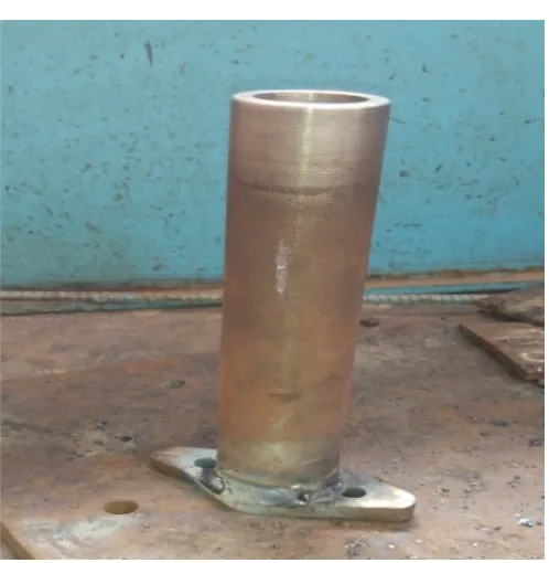
Fig .1 Convergent-Divergent Nozzle manifold
• All the operations like facing, drilling and boring
is performed by using same setup.
Fig .2 preparation of Convergent- Divergent Nozzle manifold flange
• By using four jaw chuck facing is performed on a
flange, four jaw chuck is used in order to grip properly.
Fig .3 Prepared Convergent- Divergent Nozzle manifold with flange
•
Arc welding is carried out to join flange andmanifold. The above figure shows final
4. Experimental setup and Procedure
Engine Specifications:
Fig.4 Kirloskar made diesel engine
The engine which is supplied by M/s Kirloskar Company. The engine is single cylinder vertical type four stroke, Water-cooled, Variable compression ignition engine type diesel engine. The engine is of self-governed type whose specifications are given below are used in the present work.
• Engine : Four stroke single cylinder
• Bp : 5hp
• Rpm : 1500
• Compression Ratio : 12:1 TO 20:1
• Fuel : Diesel
• No of cylinders : Single
• Bore : 80mm
• Stroke length : 110mm
• Starting : Cranking
• Work cycle : Four stroke
• Method of cooling : Water cooled
• Method of ignition : Compression ignition
Variable compression ratio:
Fig.5 Variable compression ratio in diesel engine
Observations:
Table no:1 Observations with Normal Manifold at different Compression ratios & Loads:
COMPRESSION RATIO
LOAD (kg)
SPEED (N) rpm
T1 ( ̊C) T2 ( ̊C) T3 ( ̊C) T4 ( ̊C) T5 ( ̊C) TIME (sec) 10cc
H1 mm
H2 mm
12
0 1544 26 37 29 247 119 48 26 23
2 1548 26 37 29 248 121 42 26 23
4 1536 26 37 30 264 126 38 26 22.6
6 1520 26 37 30 286 134 32 26 22.5
8 1498 25 37 30 300 145 28 26 22.2
14
0 1564 27 43 32 291 129 44 25 24
2 1560 27 39 31 263 126 36 26 23
4 1540 27 38 31 276 132 32 26 23.5
6 1532 26 39 30 305 141 29 26 22
8 1528 26 40 29 325 148 24 26 22
16
0 1577 27 35 29 172 79 51 23 24
2 1544 27 45 30 223 114 45 23 25
4 1540 27 44 31 261 114 38 23 25
6 1532 27 46 33 313 134 32 23 27
8 1528 27 45 34 323 154 26 23 27
18
0 1582 27 35 30 234 118 52 25 23
2 1560 26 36 30 257 123 46 25 22.5
4 1540 26 36 30 283 131 38 25 22.2
6 1532 26 37 30 314 142 31 25 22
8 1520 26 37 30 320 145 24 25 21.8
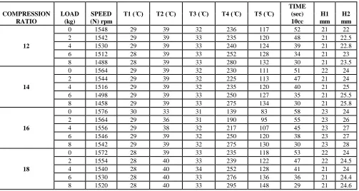
Table no:2 Observations with Convergent-Divergent Nozzle Manifold at different Compression ratios & Loads:
COMPRESSION RATIO
LOAD (kg)
SPEED (N) rpm
T1 ( ̊C) T2 ( ̊C) T3 ( ̊C) T4 ( ̊C) T5 ( ̊C) TIME (sec) 10cc
H1 mm
H2 mm
12
0 1548 29 39 32 236 117 52 21 22
2 1542 29 39 33 235 120 48 21 22.5
4 1530 29 39 33 240 124 39 21 22.8
6 1512 28 39 33 252 128 34 21 23
8 1488 28 39 33 280 132 30 21 23.5
14
0 1564 29 39 32 230 111 51 22 24
2 1544 29 39 32 225 113 47 21 24
4 1516 29 39 32 235 120 40 21 25
6 1498 29 39 33 250 127 35 21 25.5
8 1458 29 39 33 275 134 30 21 25.8
16
0 1576 30 33 31 139 83 58 23 24
2 1564 29 36 31 190 95 55 23 26
4 1556 29 38 32 217 107 45 23 27
6 1546 29 39 32 250 120 38 23 27
8 1542 29 39 32 275 130 30 23 28
18
0 1572 28 39 33 235 118 53 22 24
2 1554 28 40 33 239 122 47 22 24.5
4 1540 28 40 34 252 128 41 21 24
6 1530 28 40 33 276 136 36 21 24.4
5. RESULTS:
Experiments were conducted when the engine was fuelled with diesel and run at different compression
ratio’s namely 12.0,14.0,16.0 and 18.0 at different loads (i.e., 0, 2, 4, 6, 8) respectively with two different inlet
manifolds such as normal inlet manifold and convergent divergent nozzle inlet manifold for air suction. And the
experimental results were tabulated for both manifolds.
Table no:3 Experimental Results with Normal Manifold at different Compression ratios & Loads:
COMPRESSION RATIO
Load (kg)
Brake thermal efficiency
(η)
Mechanical efficiency
(η)
Indicated thermal Efficiency
(η)
Volumetric efficiency
(η)
MFC (Kg/hr)
SFC (Kg/KW
hr)
12
2 4.98 25.62 19.43 19.5 0.7114 1.72
4 8.94 40.6 22.02 20.55 0.7863 0.958
6 11.18 50.37 22.19 22.19 0.9337 0.766
8 12.85 57.14 22.49 22.8 1.0671 0.666
14
2 4.3 22.93 18.76 18.99 0.83 1.992
4 7.55 37 20.4 20.8 0.93375 1.135
6 10.21 46.72 21.85 22.3 1.0303 0.839
8 11.24 53.83 20.87 22.4 1.245 0.762
16
2 5.32 27.26 16.5 15.68 0.664 1.61
4 8.966 42.78 19.3 19.26 0.7863 0.956
6 11.26 52.74 20.03 22.33 0.933 0.76
8 12.17 59.74 21.55 22.4 1.149 0.704
18
2 5.97 39.09 14.07 17.34 0.649 1.558
4 9.438 51.12 17.53 18.58 0.7863 0.956
6 10.56 56.01 19.48 19.34 0.9638 0.785
8 11.64 56.6 19.75 20.13 1.245 0.766
Table no:4 Experimental Results with Convergent-Divergent Nozzle Manifold at different Compression ratios & Loads:
COMPRESSION RATIO
Load (kg)
Brake thermal efficiency
(η)
Mechanical efficiency
(η)
Indicated thermal Efficiency
(η)
Volumetric efficiency
(η)
MFC (Kg/hr)
SFC (Kg/KW
hr)
12
2 5.66 25.87 21.9 21.4 0.6225 1.511
4 9.14 40.9 22.34 23.65 0.7661 0.937
6 11.81 50.64 23.32 25.16 0.8788 0.7256
8 13.67 57.38 23.82 28.5 0.996 0.6268
14
2 5.56 32.66 17.02 30 0.6357 1.541
4 9.29 48.79 19.04 35 0.747 0.922
6 12.05 58.54 20.58 38.6 0.8537 0.711
8 13.4 64.69 20.72 38.8 0.996 0.639
16
2 6.59 34.3 19.21 30.37 0.543 1.3
4 10.729 50.95 21.056 35.16 0.664 0.798
6 13.5 60.76 21.9319 35.35 0.7863 0.634
8 15.59 67.31 22.82 39.63 0.905 0.549
18
2 5.59 29.7 18.8 27.42 0.6357 1.532
4 9.67 45.6 21.2 30.43 0.7287 0.886
6 12.66 55.5 22.78 32.56 0.83 0.677
6. Graphs:
At 16 Compression Ratio:
0 5 10 15 20 25 30 35 40
2 4 6 8
B RAK E T H E RM AL E F F ICI E NCY (η ) % Load (kg)
LOAD Vs BRAKE THERMAL EFFICIENCY(η) CD nozzle manifold Normal manifold
Fig .6 Variation of Brake thermal efficiency with Load
0 10 20 30 40 50 60 70 80 90 100
2 4 6 8
M E CH ANICAL E F F ICIE NCY( η) % Load(kg)
LOAD Vs MECHANICAL EFFICIENCY (η)
CD nozzle manifold
Normal manifold
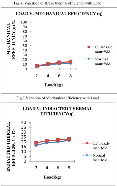
Fig.7 Variation of Mechanical efficiency with Load
0 5 10 15 20 25 30 35 40
2 4 6 8
INDIACT E D T H E RM AL E F F ICIE NCY( η) % Load(kg)
LOAD Vs INDIACTED THERMAL EFFICIENCY(η)
CD nozzle manifold
Normal manifold
Fig.8 Variation of Indicated thermal efficiency with Load
0 10 20 30 40 50 60
2 4 6 8
VO L UM E T RIC E F F ICIE NCY( η ) % Load(kg)
LOAD Vs VOLUMETRIC EFFICIENCY(η )
CD nozzle manifold
Normal manifold
Fig.9 Variation of Volumetric efficiency with Load
0 0.5 1 1.5 2 2.5 3
2 4 6 8
S P E CIF IC F UE L CO NS UM P T IO N Load(kg)
LOAD Vs SPECIFIC FUEL CONSUMPTION
CD nozzle manifold
Normal manifold
Fig.10 Variation of Specific Fuel Consumption with Load
7. Results and Discussion:
A Convergent-Divergent Nozzle manifold were used to evaluate the performance characteristics and among them it is found that 16.0 compression ratio showed better performance.
The performance of the engine was evaluated in terms of Brake thermal efficiency, Mechanical efficiency, Indicated thermal efficiency, Volumetric efficiency and Specific fuel consumption. By using these terms the efficiency of the engine is compared between normal inlet manifold and convergent-divergent nozzle inlet manifold at different compression ratios.
7.1
Specific Fuel Consumption
the manifold the specific fuel consumption falls with increasing load. The difference of specific fuel consumption is small when using different loads and compression ratios. The maximum SFC is 1.610 kg/kw-hr at 16.0 compression ratio with normal manifold and 1.300 kg/kw-hr at 16.0 CR with Convergent-Divergent nozzle inlet manifold. The higher SFC for normal manifold due to variation of air pressure, velocity and thereby less atomization of fuel.
7.2 Brake Thermal Efficiency
The variation of brake thermal efficiency with load is shown in figures Brake thermal efficiency gives an idea of the output generated by the engine with respect to heat supplied in the form of fuel. For all the compression ratios break thermal efficiency increases with load. The maximum BTE is 12.17% at 16.0 compression ratio with normal manifold and 15.59% at16.0 CR with C-D Nozzle manifold. The efficiency values for normal manifold are less when compared to Convergent-Divergent nozzle manifold. This is due to the less heat input requirement for higher power output at given load.
7.3 Volumetric Efficiency
The figures shows the variation of volumetric efficiency with load for two different manifolds. Volumetric efficiency is a measure of success with which air supply, and thus the charge is inducted to the engine. It indicates the breathing capacity of the engine. From the figure it is evident that the volumetric efficiency is varying with normal manifold is less than the Convergent-Divergent nozzle.
7.4 Mechanical Efficiency
The figures shows the mechanical efficiency for different loads and manifolds. Mechanical efficiency indicates how good an engine is inverting the indicated power into the useful power. The maximum Mechanical efficiency is 59.74% at 16.0 compression ratio with normal manifold and 67.31% at 16.5 CR with C-D Nozzle manifold. The efficiency values for normal manifold are less when compared to Convergent-Divergent nozzle manifold. Because higher fuel injection pressures increases the decrease of atomization. The fitness of atomization reduces the ignition lag.
7.5 Indicated Thermal Efficiency
The figures indicates variation of indicated thermal efficiency at different loads for both the manifolds. Indicated power is the power developed at the engine cylinder, it can be noted from fig. that the indicated thermal efficiency is more for Convergent-Divergent
nozzle manifold when compared to normal manifold for different compression ratios.
8.Conclusions:
The Performance characteristics of an variable compression ratio diesel engine without nozzle and with nozzle in the intake manifold were compared in the present work. The following are the conclusions based on the experiment results obtained while operating the single cylinder water cooled variable compression ratio diesel engine with normal inlet manifold and Convergent-Divergent nozzle inlet manifold at different compression ratios 12.0,14.0,16.0 and 18.0 respectively. By tabulating obtained values and those values are compared with load applied. Finally performance characteristic curves are drawn and efficiencies are identified.
When the obtained results are compared at different compression ratios (12.0,14.0,16.0 and 18.0 ) and among them it is found that 16.0 compression ratio showed better performance for both manifolds. From the compared values at 16.0 compression ratio the Convergent-Divergent nozzle manifold leads to the better efficiency than normal inlet manifold for air suction.
The Brake thermal efficiency is increased by
3.42%.
The Mechanical efficiency is increased by
7.57%.
The volumetric efficiency is increased by
17.23%The Indicated thermal efficiency is increased by 1.27%
The Specific fuel consumption is decreased by
0.155%
References
[1] Montgomery, D.T., et al., Effect of Injector Nozzle Hole size and Number of Spray Characteristics and the Performance of a Heavy-Duty D.I. Diesel Engine, in SAE Paper. 1996.p. 962002.137
[2] He, L. and F. Ruiz, Effect of Cavitation on Flow and Turbulence in Plain Orifices for High-Speed Atomization.
Atomization and Sprays. 5: p. 569-584.
[3] Knox-Kelecy, A.L. and P.V. Farrell, Internal Flow in a Scale Model of a Diesel Fuel Injector nozzle, in SAE Paper. 1992. p. 922308.
[4] Benajes, J., et al., Analysis of Influence of Diesel Nozzle Geometry in the Injection Rate Characteristic. J.
Fluids Eng., 2004. 126: p. 63-71.138
[5] Desantes, J., et al., Experimental characterization of outflow for different diesel nozzle geometries, in SAE Paper. 2005. p. 2005-01-2120.
International Journal of Mechanical and Industrial Engineering (IJMIE), ISSN No. 2231 –6477, Volume-1, Issue-2, 2011
[7] S.Ravi Babu, K.Prasada Rao and P.Ramesh Babu Performance Evaluation of an IC Engine in the Presence of a C-D Nozzle in the Air Intake Manifold, IJCET- Vol.3, No.4 ,October 2013.
[8] Syed Ashfaq, S. A. Khan Experimental Investigation of Flow through Convergent Nozzle and Influence of Micro Jets on the Enlarged Duct Flow Field IPASJ International Journal of Mechanical Engineering (IIJME) Volume 2, Issue 3, March 2014.
[9] Dr. Hiregoudar Yerrennagoudaru , Kullaya Swamy K B, Effect of Nozzle holes and Turbulence injection on diesel engine performance, International Journal of Recent Development in Engineering and Technology ,Volume 2, Issue 6, June 2014)
[10] Pravin D. Solanki, Prof. V. Y Gajjar Effects of Intake Manifold Design on Diesel Engine Performance and Emissions, IJSRD - International Journal for Scientific Research & Development| Vol. 2, Issue 08, 2014.
[11] S.Jaichandar, K.Annamalai, V.Elango, P.Arikaran and V. Antony Aroul Raj Effects of varying the compression ratio on the performance of a biodiesel fuelled diesel engine, IJAET- Vol.3, Aug 2014.
[12] Vijay Kumar Attri, Vijay Kumar Sharma, Saurabh Kumar Singh and Manish Saraswat Effect of Compression Ratio on Performance and Emissions of Diesel on a Single Cylinder Four Stroke VCR Engine, International Journal of Emerging Technology and Advanced Engineering,Volume 5, Special Issue 1, April 2015.
[13] K.Satyanarayana, Vinodh Kumar P, T.V.Hanumantha Rao and S.V.Umamaheswara rao Variable Compression Ratio Diesel Engine Performance Analysis, International Journal of Engineering Trends and Technology (IJETT) – Volume 28 Number 1 - October 2015.