ABSTRACT
GAY, ALEX MICHAEL. Fabrication and Classification of Dual-Matrix Composites for Deployable Space Applications (Under the direction of Dr. Mark Pankow).
High strain composites (HSCs) are materials capable of large deformations, but they
also have high stiffness which allows them to reconfigure and carry loads. As such they are
of interest for deployable space structures. HSCs aim to reduce the weight, cost, and
complexity of deployable space structures by replacing traditional metallic structures and
mechanical hinges. Dual-matrix composites are a subset of HSCs that utilize the high
flexibility of carbon fiber reinforced silicone (CFRS) alongside a stiffer epoxy matrix to create
localized flexible hinge regions within a thin carbon fiber composite. Intrinsic hinges allow
for fabrication of origami dual-matrix composites that present an interesting opportunity for
space structures; the folding arrangements that can be achieved allow for highly efficient
packing and produce structures capable of self-deployment. Origami folding techniques can
be used to create flat folding deployable structures and mechanical metamaterials which can
then be applied to dual-matrix composites. However, their manufacture is not well-established
thus fabrication of dual-matrix composites presents a challenge. Accessible out-of-autoclave
methods of dual-matrix composite fabrication are explored. A computer numerical control
(CNC) plotter is developed to accurately and consistently infuse silicone into complex origami
hinge architectures. Dual-matrix composite samples were tested to characterize the response
© Copyright 2017 Alex Michael Gay
Fabrication and Classification of Dual-Matrix Composites for Deployable Space Applications
by
Alex Michael Gay
A thesis submitted to the Graduate Faculty of North Carolina State University
in partial fulfillment of the requirements for the degree of
Master of Science
Aerospace Engineering
Raleigh, North Carolina
2017
APPROVED BY:
_______________________________ _______________________________
DEDICATION
Mom and Dad, thanks for providing me with every opportunity to succeed and encouraging to
BIOGRAPHY
Alex Gay received his Bachelor of Science degree in Materials Science and Engineering from
Clemson University in May 2015. His desire to contribute to the space industry led him to
North Carolina State University where he began work on his Master of Science in Aerospace
Engineering that fall. He began his work with Dr. Mark Pankow fabricating dual-matrix
origami composite structures for use in deployable space structure applications. Over the
summer of 2016 Alex had the opportunity to intern at NASA Langley Research Center in
Hampton, VA where he continued working with flexible carbon fiber composites for
ACKNOWLEDGMENTS
First and foremost, I would like to thank my advising professor Dr. Mark Pankow for providing
me the opportunity to fabricate and explore unique composite materials in the great
environment that is the BLAST Lab. Not many people have the opportunity to build a carbon
fiber origami crane, let alone a robotic assistant to help them do it again.
Charlie, thanks for all the help you provided me from composite fabrication to
machining stuff to help with my projects. Cody, thanks for all the help with the printer and
everything else under the ceiling. Jordan, thanks for all the knowledge, composites and
otherwise, you provided. John and Tyler, thanks for all the work you guys put in to help get
the printer up and running. Thanks to everyone else in the BLAST Lab, you guys have all
helped me out in some way or another and have been great to work with these last couple years.
TABLE OF CONTENTS
LIST OF TABLES ... vii
LIST OF FIGURES ... viii
Chapter 1 – Introduction ... 1
1.1 – Background ... 1
1.2 – Research Objectives ... 6
1.3 – Research Questions ... 6
1.4 – Thesis Outline ... 7
Chapter 2 – Complex Origami Structures ... 8
2.1 – Origami Engineering ... 8
2.1 – Origami Mechanical Metamaterials ... 10
Chapter 3 – Hand Fabrication of Dual-Matrix Composites ... 14
3.1 – Materials ... 14
3.2 – Fabrication Methods ... 15
3.3 – Fabrication Results... 16
3.4 – Comparison of Traditional Origami to Composite Origami ... 20
3.5 – Challenges of Hand Fabrication ... 21
3.6 – Inspirations for Plotter ... 26
Chapter 4 – CNC Plotter for Dual-Matrix Composite Fabrication ... 27
4.1 – Construction of Plotter ... 27
4.2 – Controlling the Plotter... 32
4.3 – CNC Plotter Results ... 34
Chapter 5 – Mechanical Characterization of Dual-Matrix Composites ... 39
5.1 – Testing Setup ... 39
5.2 – Material Properties ... 41
5.3 – Discussion ... 44
5.4 – Conclusions ... 45
Chapter 6 – Conclusions ... 46
6.1 – Dual-Matrix Composite Origami ... 46
6.2 – CNC Plotter for Dual-Matrix Composites ... 46
6.3 – Dual-Matrix Composite Material Testing ... 47
6.3 – Future Work ... 47
REFERENCES ... 48
APPENDICES ... 51
Appendix A – Sprinter Configuration File for Silicone Plotter (Configuration.h) ... 52
Appendix B – Slic3r Configuration Bundle for Silicone Plotter ... 60
LIST OF TABLES
Table 1. Mechanical properties of Matrix Systems ... 14
Table 2. Hardware specifications of plotter ... 32
Table 3. Test hinge model parameters ... 35
LIST OF FIGURES
Figure 1. DLR’s Omega boom half-shell and coiled full boom [4] ... 2
Figure 2. Tape-spring hinge initial configuration, flattened, and folded [5] ... 3
Figure 3. Fiber microbuckling in a soft-matrix composite [6] ... 3
Figure 4. Carbon Fiber Reinforced Silicone (CFRS) reflecting surface in deployed and folded states [7] ... 4
Figure 5. Flexible dual-matrix composite schematic diagram [9] ... 4
Figure 6. Folding process of conical dual-matrix composite antenna [10] ... 5
Figure 7. PUFFER in standard and flattened configurations [12] ... 8
Figure 8. Potential origami morphing radiator designs [13] ... 9
Figure 9. Deployment of modified flasher deployable solar array concept [17] ... 10
Figure 10. Deployment of carbon fiber dual-matrix modified flasher model [18] ... 10
Figure 11. 3D folding Miura cellular metamaterial [19] ... 11
Figure 12. 3D cellular origami metamaterial with single-axis rigidity [20] ... 11
Figure 13. Fabrication of Miura tube and extension/retraction mechanism [21] ... 12
Figure 14. Zipper-, Aligned-, and Internally-Coupled Miura tube configurations [21] ... 12
Figure 15. Canopy and Bridge Structures created using Miura tubes in various states of deployment [21] ... 13
Figure 16. Paper fold pattern and pre-silicone-infusion bounded carbon fiber of origami Wolf ... 16
Figure 17. Silicone spreading under bounding material on underside of origami Wolf ... 17
Figure 18. Carbon fiber origami frog and wolf ... 17
Figure 19. Unfolded and folded carbon fiber origami Crane ... 18
Figure 20. Folding of dual-matrix composite Miura sheet ... 18
Figure 21. Bounded and fully infused halves of Miura tube ... 19
Figure 22. Various configurations of completed dual-matrix composite Miura tube ... 19
Figure 23. Comparison of jump heights of carbon fiber and paper origami frogs ... 20
Figure 26. Inconsistencies of hinge width and nonparallel boundaries of bounded origami Frog
pattern ... 22
Figure 27. Sample composite using guide tape (marked with red line) method and partially removed guide tape (dashed line) ... 23
Figure 28. Warping of fabric during Crane fabrication due to tape stretching and relaxation ... 24
Figure 29. Thickness interference testing sample: two layer flat fold and interference experienced at three layers ... 25
Figure 30. Silicone plotter... 28
Figure 31. Widened wheelbase for y-axis stability ... 28
Figure 32. 3D printed motor mount and timing belt pulley axle mounts ... 29
Figure 33. Y-axis end stop and 3D printed mount ... 29
Figure 34. Glass print bed and attachment bracket ... 29
Figure 35. Sanguinololu board configuration ... 30
Figure 36. Carbon fiber sample before silicone infusion using plotter... 31
Figure 37. Syringe pump extruder assembly ... 31
Figure 38. Slic3r and Pronterface views of Blintz origami hinge geometry to be plotted .... 33
Figure 39. Silicone that failed to impregnate fabric (pre-PTFE O-ring) ... 34
Figure 40. Top and underside of width and thickness tests (increasing width and thickness from left to right), ‘barbs’ highlighted ... 35
Figure 41. Simple hinge specimens for testing ... 36
Figure 42. Blintz origami fold pattern ... 36
Figure 43. Blintz origami folding process ... 37
Figure 44. Fiber breakages within hinges of blintz origami ... 38
Figure 45. Schematic of bending fixture [22] ... 39
Figure 46. Bending test setup in Instron load frame and closeup of test specimen ... 40
Figure 47. Vic-3D overlay of calculated curvature at two points during bending test ... 41
Figure 49. Moment vs. Curvature of plotted Mold Star 30 sample (solid loading, dashed
unloading) ... 43
Figure 50. Moment vs. Curvature of plotted Smooth-Sil 950 sample (solid loading, dashed
Chapter 1 – Introduction
1.1 – Background
Current technology requires that structures for space missions fit inside the cargo volume of
their launch vehicle. Unfortunately, many space missions necessitate large structures. The
volumetric constraints imposed by launch capabilities have been addressed in the past by
utilizing deployable capabilities and structural modularity. These allow for payloads to expand
to many times their packaged size or be assembled further in space, respectively. Development
of efficient packing technologies is critical to sending larger structures into space without
requiring larger and more expensive launch vehicles. This study examines fiber reinforced
composites able to undergo large strains that are capable of ushering in the next generation of
deployable space structures.
Traditional deployable space structures utilize mechanical hinges to expand from their
packaged state. While the performance of mechanical hinges is well understood, they present
their own challenges in the form of moving parts and high mass. Reducing the total moving
parts within a space mission is ideal since each moving part is a potential point of failure and
cannot easily be serviced after launch. The hinges add cost and mass because of the high
precision demanded and interface surfaces required [1]. Other deploying space structures have
been tested that weld the structure as it deploys [2], but this prevents reconfiguring of the
structure after deployment if necessary. High strain composites (HSCs) have the capacity to
mitigate these issues by taking the place of metallic, mechanical solutions with more
lightweight, monolithic elements.
High strain composites are materials capable of large deformations, but they also have
high stiffness which allows them to reconfigure and carry loads. The mechanics of stiff fibers
within a softer matrix allow HSCs to achieve large strains without phase transformations like
those seen in superelastic metallic alloys. The processes that allow such deformations are
reversible which allows HSCs to be strained and released repeatedly. The dependency of the
properties of HSCs on their structural configuration allows for applications that could not be
metallic high strain deploying structures and have flown on numerous spaceflight missions,
but when comparing material properties to those of the metallic alternatives, glass fiber
reinforced composite structures offered no advantage over their metal cousins so there was not
much interest. In recent years, however, this has changed as improved carbon fiber
technologies have allowed for strong, light, and thermally stable composites, allowing for
technological solutions capable of surpassing those achieved using rigid, metallic deploying
structures [3].
Numerous designs that take advantage of HSCs have been realized for deployable
space applications. One well-known example is the omega cross-section boom developed by
the German Aerospace Center (DLR) for use on solar sail deployment. The boom is made of
two omega shaped carbon fiber shells joined together to form a closed cross section as seen in
Figure 1. The extremely small thickness of the material allows the boom to flatten without
damaging the fibers or matrix. The flattening ability and flexibility gives the boom the ability
to be rolled around a central circular hub and packed into a small volume. Upon deployment,
the boom returns to its fabricated omega shape and regains its stiffness along its length [4].
Developments have also been made on hinged booms with sections capable of folding
to allow compact packing for launch and deployment in space. A section of a circular
cross-section boom is cut out to form a tape-spring hinge that is able to bend while the rest of the
packed in a compact configuration, see Figure 2. Since the energy is stored using linear elastic
strain the boom can self-deploy once released [5].
The examples discussed up to this point have all used a relatively stiff polymer matrix
material. Although the fibers are much stiffer than the matrix material, there is also the option
of utilizing a hyperelastic matrix material to allow even more extreme deformations of the
composite. By infusing the carbon fibers with a material such as a silicone rubber, the thin
composites can be folded without damaging the fibers. The soft matrix allows the fibers to
move and experience microbuckling when the composite is in bending which prevents the
inherently brittle fibers from breaking, see Figure 3 [6]. These extreme folding capabilities
present opportunities for new developments in highly packable structures.
One such example of a structure that has taken advantage of the great flexibility of
carbon fiber reinforced silicone (CFRS) is a deployable umbrella type reflector. This particular
reflector design utilizes a triaxial woven carbon fiber to reinforce a silicone matrix and is highly
applicable to satellites because of its ability to deploy a large dish from a small package, see
Figure 4. The geometry of the reflecting surface is highly accurate and dimensionally stable
FIGURE 2. TAPE-SPRING HINGE INITIAL CONFIGURATION, FLATTENED, AND FOLDED [5]
with a very low mass. The design parameters of the reflecting surface can be modified
depending on the frequencies to be gathered by the reflector [7].
Dual-matrix composites are a subset of high strain composites that utilize the high
flexibility of CFRS alongside a stiffer epoxy matrix to create localized flexible hinge regions
within a thin carbon fiber composite. The independence of the two matrix regimes results in a
relatively stiff composite with an epoxy matrix and a much softer and more flexible composite
with a silicone matrix. This allows for intrinsic hinges within a continuous deployable
composite structure as seen in Figure 5 [8].
Dual-matrix composites have garnered significant interest with regard to deployable
space structures for their low mass and extremely high packing efficiency. The localized
folding regions allow for deliberate and intricate folding patterns to be realized. Folding
techniques have been applied to dual-matrix composites to create highly packable deployable
FIGURE 4. CARBON FIBER REINFORCED SILICONE (CFRS) REFLECTING SURFACE IN DEPLOYED AND FOLDED STATES [7]
CubeSat missions. The conical composite shell contains an embedded conductive element for
the antenna structure. The composite shell is able to be flattened then Z-folded for further
compaction as seen in Figure 6 [10]. Other dual-matrix composite concepts that have been
investigated for space applications include foldable booms [9], beams containing flexible
hinges [11], and origami structures [3].
Origami dual-matrix composites present an interesting opportunity for space structures
because the folding techniques that can be realized allow for highly efficient packing and
produce structures capable of self-deployment. Substituting classical origami’s paper with
high-performance materials like fiberglass and carbon fiber dual-matrix composites produces
structures with flexible regions capable of emulating an origami fold and very rigid regions
elsewhere capable of supporting significant loads. This combination of stiffness and flexibility
results in structures that can pack tightly but still serve as structural elements for a potential
space mission and deploy to sizes much larger than their packaged configuration.
It has been shown that high strain and dual-matrix composites present the opportunity
to remove the need for heavy and expensive complex mechanical hinges from deployable
structures. These materials provide new methods of packaging and deploying structures
aboard payloads constrained by the volumetric limitations of spacecraft. However, their
manufacture is not well-established thus fabrication of dual-matrix composites presents a
challenge. Fabrication of dual-matrix composites by hand often results in hinge
inconsistencies and geometric flaws and is very time consuming, resulting in costly downtime.
The issues of dual-matrix composite fabrication need to be ironed out before they can be
regularly implemented into spaceflight missions.
1.2 – Research Objectives
Fabrication methods of dual-matrix composites will be investigated to expand understanding
of accessible and out-of-autoclave techniques. A novel computer numerical controlled (CNC)
method of dual-matrix composite fabrication will be explored and developed to increase
accuracy and consistency of hinge regions to the level demanded by complex origami layouts.
Dual-matrix composites will be manufactured using origami techniques to create deployable
structures. Comparisons will be made between hand fabricated dual-matrix composites and
those made using the CNC method. Dual-matrix laminates will be experimentally tested using
new test methods to accurately characterize bending stiffness of coupon samples.
1.3 – Research Questions
• How can fabrication of dual-matrix composites be made more reliable to consistently attain the accuracy demanded by origami folds?
• How can origami folding of flexible composites be integrated into deployable
structures for space applications?
• How can dual-matrix composites subjected to extreme bending be characterized and
1.4 – Thesis Outline
Chapter 2 will investigate origami folding techniques to create deployable structures capable
of efficient packing that can be applied to complex dual-matrix composite architectures.
Chapter 3 will explore methods of fabricating dual-matrix by hand, examine some of the
challenges presented in doing so, and provide the basis for the development of a CNC device
to assist in manufacture of dual-matrix composites. Chapter 4 will detail the development of
a CNC ‘printer’ for producing more consistent silicone geometries infused into a carbon fiber
fabric and the outcomes of that endeavor. Chapter 5 will investigate an empirical test method
to characterize highly flexible composite materials under extreme bending. Chapter 6 will
Chapter 2 – Complex Origami Structures
This chapter will explore the field of origami engineering in which inspiration is drawn from
traditional origami folding techniques to devise folding and morphing structures. These
folding structures are of interest because the ability to integrate specific, localized hinge
regions of extreme flexibility allows dual-matrix composites to adapt origami concepts to
produce structures using high-performance composite materials that can be used aboard
space-faring missions.
2.1 – Origami Engineering
Origami is the traditional Japanese art of folding a flat piece paper into three-dimensional
shapes and figures. Traditionally, origami is used to create decorative pieces, but by adapting
traditional folding techniques, it is possible to create practical structures. Origami folding
techniques provide inspiration for new developments of adaptive, morphing, and
small-packing structures. NASA’s Pop-Up Flat Folding Explorer Robot (PUFFER), seen in Figure
7, is an example of an origami-inspired engineering design. The robotic explorer is designed
as a small companion to rovers that can explore areas that may be unfavorable for the larger
rover. The PUFFER’s wheels fold inward such that the robot can almost completely flatten
itself, allowing for exploration of low vertical clearance areas and efficient packing so one or
more explorers can be easily carried aboard the rover itself [12]. While the PUFFER uses an
part of their structure. NASA and Brigham Young University (BYU) have explored active
radiator concepts for satellites that can be seen in Figure 8. The radiators use their origami
architectures to change shape; the resulting changes in depth of the cavities controls the heat
loss of the radiators [13]. One of the major stimuli of interest in origami engineering was the
Miura folded solar array that flew on the Japanese Space Flyer Unit in 1995 [14], [15]. The
structure introduced by Miura folding exhibits a memory effect that allows it to be easily
opened and closed [16]. Since then, researchers at BYU have explored further concepts for
self-deploying, highly packable solar arrays. A modified ‘flasher’ model was developed that
allowed rigid solar cell elements to be rolled up compactly without damaging the cells, see
Figure 9 [17]. It has been shown that this concept can be adapted to and replicated using
dual-matrix composite materials as seen in Figure 10 [18].
2.1 – Origami Mechanical Metamaterials
In the context of this work, mechanical metamaterials refer to materials with properties
primarily determined by the geometric configuration of the material. The Miura folding
technique provides a versatile basis capable of being adapted to metamaterials. A partially
folded Miura-folded sheet on its own is a simple shell metamaterial; the localized fold pattern
alters the bulk mechanical properties, most notably, the Miura sheet has a negative in-plane
Poisson’s ratio. By stacking Miura sheets of slightly different geometries, a 3D, folding
cellular metamaterial structure is created, as seen in Figure 11. Such structures can be tailored
to automatically arrest folding by incorporating alterations of the Miura unit cell within layers
depending on the desired amount of folding [19].
FIGURE 9. DEPLOYMENT OF MODIFIED FLASHER DEPLOYABLE SOLAR ARRAY CONCEPT [17]
Other cellular metamaterial structures have been developed that exhibit highly
anisotropic behaviors. The structure shown in Figure 12 is foldable along its x and y axes but
rigid in the z direction. By isolating the Miura pattern segments within the structure, it is
possible to fabricate the cellular metamaterials in a flat configuration to later be expanded into
its 3D configuration [20].
By combining elements from a Miura sheet it is possible to make flattening and
flat-folding tubes. The tube is created when a row of Miura cells is joined along the edges with its
mirror image. When fully extended, the tube lies flat in its XY plane and when fully retracted
it folds flat in its YZ plane; both the fabrication and extension/retraction can be seen in Figure
FIGURE 11. 3D FOLDING MIURA CELLULAR METAMATERIAL [19]
13. The tubes can be coupled with another in different configurations to bolster the mechanical
properties. Three different configurations can be seen in Figure 14. The zipper-configured
tubes are stiffer than the other two configurations and the only ones to retain the flattening
characteristics. The tubes can be further assembled into larger cellular structures that maintain
a degree of flattening and deployability. Deployable structures that have been fabricated
include an architectural canopy and a bridge; both can be seen in Figure 15. Both the canopy
and bridge have a high out-of-plane stiffness and are capable of supporting such loads. These
designs present opportunities for future developments in origami-inspired architecture [21].
The concepts presented above can be applied to dual-matrix composites by infusing
silicone into the locations of the origami fold lines creating flexible folding regions and stiff
panels elsewhere. The carbon fiber reinforcement provides a stiffer structure than paper while
being lighter than metallic solutions, and it is also continuous throughout the origami structure
unlike other materials that would require a discrete hinge. The ability to manufacture these
origami metamaterials using carbon fiber would produce lightweight, high-performance
FIGURE 13. FABRICATION OF MIURA TUBE AND EXTENSION/RETRACTION MECHANISM [21]
deployable structures. The promise of such structures drives the need for accessible methods
of manufacturing the dual-matrix composite materials involved.
Chapter 3 – Hand Fabrication of Dual-Matrix Composites
This chapter will discuss the materials involved in the fabrication of dual-matrix composites
and the methods of fabricating complex folding architectures with integral hinges. Dual-matrix
composite origami are fabricated and folded. The challenges presented by hand fabrication of
dual-matrix composites are discussed, and the inspirations for devising a CNC plotter to infuse
silicone hinge regions are laid out.
3.1 – Materials
The materials used within this study were primarily selected for convenience; the techniques
used can easily be applied to different material systems depending on the desired properties of
the final composite parts. For spacefaring composites, for example, it is crucial that the
materials involved do not outgas under vacuum lest they release anything that might adversely
affect other elements of the payload. As long as all the material systems within the composite
are compatible, substitutions can be freely made to tune the mechanical properties of the
finished product or the fabrication parameters, such as cure times or mechanisms.
The fiber reinforcement used in the fabrication of dual-matrix composites in this study
was primarily a 3k plain-woven carbon fiber fabric. The 3k fabric offers a balance between
rigidity of the stiff regions and overall fabric thinness. The epoxy resin system used for the
stiff regions is Fibre Glast’s 2000 series with 2060 hardener, which results in a one hour pot
life. The epoxy resin system reaches full cure after 36 hours. Two different two-part silicone
rubber systems were tested for use in the flexible hinge regions: Smooth-On Mold Star 30 and
Smooth-On Smooth-Sil 950. Both silicone rubber systems have a 45 minute pot life; the Mold
Star 30 cures in 6 hours while the Smooth-Sil 950 takes 24 hours. The relevant mechanical
properties of each matrix system can be seen in Table 1.
Matrix System Modulus [psi] Elongation [%] Viscosity [cps] Tear strength [pli]
Fibre Glast 2060 Epoxy 418525 1.90 925 -
Smooth-On Mold Star 30 96 339 12500 88
3.2 – Fabrication Methods
In order to create composite laminates with integrated hinges, it is necessary to keep the two
distinct matrix materials independent from one another. The fabrication techniques used in
this study are derived primarily from those developed by White [16] with the intention of being
out of autoclave and non-proprietary.
The addition of a secondary matrix system to the composite laminates mandates
alterations to conventional composite manufacturing methods. As a means of maintaining the
independence of the two matrices, they are infused into the fiber reinforcement and cured
individually. The hyper-elastic silicone matrix is impregnated into the hinge regions first, and
the stiff epoxy matrix is impregnated into the rest of the laminate second. The presence of the
silicone matrix prevents the ingress of the epoxy matrix into the hinge regions, but during the
infusion of the silicone, it must be restricted to prevent it from spreading to more area than the
desired hinge region. To that end, tape was applied to the carbon fiber fabric to outline the
hinge regions and prevent the silicone from spreading outward to areas beyond those desired.
Painter’s tape was initially used because it sticks to the carbon fiber fabric without bonding
and can be removed without warping the woven fabric, but electrical tape later replaced it as
the bounding material because it could also be removed easily but created a cleaner silicone
boundary. For more intricate origami hinge geometries, the origami was first folded from
paper and the folds were highlighted on the paper then copied onto the carbon fiber to provide
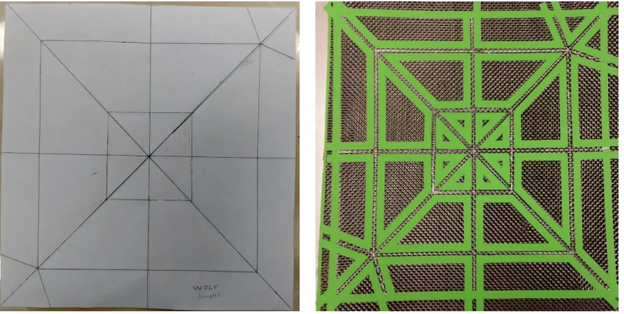
guide lines for the bounding process. A paper origami fold pattern of a wolf and the
corresponding carbon fiber before silicone infusion can be seen in Figure 16. After the
boundaries are applied to the carbon fiber fabric, the two-part silicone rubber system is mixed
and carefully poured onto the fabric in between the tape boundaries. Light pressure was then
applied by hand to ensure impregnation through the thickness of the fabric taking care to keep
from spreading the silicone outside of the bounded regions. After the silicone has cured in
open air, the excess silicone that cured on top of the bounding material was carefully peeled
bounding material was then carefully removed in preparation for the epoxy resin infusion. The
epoxy resin system was then mixed and applied by hand before vacuum bagging and allowing
the epoxy to cure under vacuum. Once the epoxy is cured, the composite is removed from the
vacuum bagging setup and any excess material is trimmed away and the composite can be
folded.
3.3 – Fabrication Results
Although the tape serves as a boundary for the spread of the silicone, it does not perfectly
inhibit the spreading of the silicone. On the top surface where the bounding material is applied,
the boundary is usually very clean and sharp. On the underside, however, the silicone often
spreads out a bit to the fabric under the bounding material. This phenomenon can be seen in
Figure 17. The silicone spread on the underside can be minimized by bounding the hinge
regions on both the upper and lower surfaces of the fabric, but for origami fold patterns this is
both time consuming and difficult to properly align. During the vacuum bagging process the
pressure from the atmosphere often pushes a small amount of epoxy onto the top and bottom
of the silicone infused regions; this results in a slightly stiffer first fold and minor cracking can
be heard when initially folding.
Several origami structures were fabricated to test the feasibility of the methods
described above. A wolf and frog were successfully folded as seen in Figure 18. An origami
crane was also fabricated and folded and can be seen in Figure 19. The crane was fabricated
using a 1k carbon fiber plain-woven fabric because the thinner fabric is not as severely affected
by the stacking and overlapping of multiple layers due to the folding pattern. A Miura sheet
was fabricated and its folding stages can be seen in Figure 20.
FIGURE 17. SILICONE SPREADING UNDER BOUNDING MATERIAL ON UNDERSIDE OF ORIGAMI WOLF
A Miura tube was fabricated using dual-matrix composite materials. A small four-cell long
tube was made as a representative unit of the tube structure to prove the feasibility. The
structure of the tube cannot be made from a single flat piece of material so it was necessary to
fabricate the two halves separately and join them subsequently. Each half was fabricated with
tabs on either side for joining the halves together. The bounded and fully infused halves can
be seen in Figure 21. When assembling the halves it was found that having two sets of tabs on
each side caused interference between the sets, so one redundant set of tabs was removed from
each half. After cutting the excess material off each half, the two halves were glued together
to form the completed tube which can be seen in Figure 22. The tube flattens at no extension
FIGURE 21. BOUNDED AND FULLY INFUSED HALVES OF MIURA TUBE
and full extension like the paper equivalents and shows promise on its own as a self-deploying,
packable boom that could be applied to space missions.
3.4 – Comparison of Traditional Origami to Composite Origami
The hinges in the dual-matrix composite origami structures contain significantly more strain
energy than their paper equivalents. As a result, the hinges have a high tendency to return to
their unfolded state. The difference between the carbon fiber and paper origami is immediately
evident when comparing the two origami frogs. As seen in Figure 23, the carbon frog jumps
to deployable structures because it allows for self-deploying structures that rely only on
internal strain energy introduced when packaging the structure.
3.5 – Challenges of Hand Fabrication
When it comes to fabricating complex hinge geometries, there are many challenges that present
themselves. The nature of origami mandates that the fold locations are highly accurate. When
folding paper origami, if the folds are slightly off it can prevent the final structure from folding
properly. This effect is amplified by the highly stiff panels of origami dual-matrix composites;
if the hinges are slightly misaligned it can result in a structure that will not fold.
The Miura tube as discussed above that was fabricated exhibited the problem of
inability to fold. The hinges appeared to be accurate, but they were far enough off to prevent
the tube from reaching zero extension and the associated flattening which can be seen in Figure
24. After a few failed efforts a stencil, which can be seen in Figure 25, was laser cut to ensure
the guide lines were as accurate as possible when applying the bounding material. With the
accurate stenciled guide lines it was possible to fabricate a Miura tube that flattened as
intended. Great care had to be taken when gluing the halves together because tabs that are
attached only slightly out of the required position can negate near-perfect hinge locations.
It is not desirable to have to make a stencil for every dual-matrix composite hinge
geometry as it adds an extra step and extra cost to each part. Additionally, even with
high-accuracy guide lines, it is still difficult to maintain straight, parallel lines and constant width
when applying the tape boundaries for the silicone infusion. Upon close inspection of Figure
26 it can be seen that even for hinges that have only perpendicular intersections the boundaries
are not always parallel and the hinges are not of constant width. As such, it is desirable to
develop a method of producing boundaries that are parallel and constant width. To that end, a
strip of tape was used as a guide for the application of the bounding tape. Tape was applied
atop the silver guide line to serve additionally as a width guide. The hinge will then take on
the width of the guide tape as the bounding tape is butted up against the guide tape during
application. Once the guide tape and bounding tape are applied, the bounding tape is cut with
a razor blade where it overlaps the desired hinge region taking great care not to cut the fibers
beneath. A sample composite fabricated using this technique can be seen in Figure 27 with all
the tape applied, the guide tape with a red line drawn on it, and with one of the pieces of guide
tape and the overlapping bounding tape removed. When the green painter’s tape was used it
was easy to accidentally cut the fibers with the razor blade, but when using electrical tape this
problem was nearly completely mitigated because of the electrical tape’s tendency to tear
cleanly once cut compared to the painter’s tape.
Although the electrical tape forms a cleaner silicone boundary than the painter’s tape
and lessens the fiber damage when removing the guide tape, it is not a perfect solution.
Electrical tape is quite stretchy, and while this is nice for fixing damaged wires, it presents a
challenge when using it as a bounding material on the carbon fiber fabric. When applying the
electrical tape for the hinge area boundaries, great care must be taken to avoid introducing any
elastic strain into the tape by stretching it out. When the tape is released, it will relax to a state
of zero or near-zero strain and cause deformation of the carbon fiber fabric it is stuck to. Fabric
warping due to tape stretching and relaxation that was experienced during the fabrication of
the dual-matrix composite origami crane can be seen in Figure 28. The fabric had to be pulled
so that the tape returned to a stretched state and taped down so the fabric would be flat during
silicone infusion. Once the silicone was infused and the tape was removed, the epoxy resin
was infused without problem.
In addition to the logistical challenges of dual-matrix fabrication, there are also
environmental considerations that must be made. Like conventional composites fabricated
using vacuum bagging techniques, the dual-matrix composite fabrication process generates
significant waste that cannot be reused or recycled because of the epoxy resin that impregnates
it during fabrication. However, dual-matrix composite fabrication also generates a significant
amount of waste in the bounding material. During the bounding process, the tape is cut to very
specific shapes determined by the hinge geometry. This results in the bounding material being
unusable for other hinge geometries. Even if a second part were desired immediately, it would
be exceedingly challenging to replace the bounding material accurately similarly to the
boundaries. For large, complex parts such as the crane, a lot of bounding material is required
to separate the hinge regions from those that will later be infused with epoxy resin. In addition
to the bounding tape, the guide tape also goes straight to waste. Often the guide tape has to be
torn or cut during removal. All in all, a lot of material goes to waste during dual-matrix
composite fabrication.
On the design side of the spectrum, material thickness must be considered if the folded
configuration of the structure results in overlapping layers. Given the thickness of the woven
carbon fiber fabric, it does not fold as readily as paper. A sample part was fabricated to test
how much the layers interfere with one another when complex folds are made. The sample
was designed with numerous hinges running the width of the sample and a single long hinge
running the length. This allows for the sample to be folded like an accordion along the length
then folded in half along the width to observe how easily the stacked layers fold. Using this
sample made from a woven 3K carbon fiber fabric, it appears that after two stacking layers it
becomes difficult to fold the composite completely flat. The unfolded test part and
double-stacked and triple-double-stacked layer folds can be seen in Figure 29. In order to account for the
thickness of the composite, the hinges that would be on the outside of the fold would have to
be wider to allow the hinge to bend around the inner layers. This is completely dependent on
the geometry of the structure and depending on the interactions between the layers it may be
unnecessary, but this is the reason the crane was made with 1K fabric over 3K fabric.
3.6 – Inspirations for Plotter
Although the dual-matrix composite fabrication methods detailed above are desirable for their
ease of access, they are not the most reliable when fabricating complex origami hinge
geometries. As such, it would be beneficial to devise a method of fabrication that offers more
consistency and reliability. An optimal fabrication method would ideally eliminate or mitigate
all or most of the challenges discussed in the previous section. A novel computer numerical
controlled (CNC) silicone infusion system was explored as a means to accurately and
consistently infuse the silicone hinges without the need for stencils or more advanced bounding
methods. An added benefit of giving the computer the ability to accurately infuse specific
regions is the lack of need for bounding material. As a result, it also eliminates all the waste
generated by the bounding process. Creation of a CNC plotter for silicone infusion in
dual-matrix composite manufacture has the potential to eliminate the boundary inconsistencies and
minimize accuracy issues presented and dramatically decrease the waste generated by the
Chapter 4 – CNC Plotter for Dual-Matrix Composite Fabrication
A computer numerical control (CNC) plotter inspired by 3D printers was created for reliable
and consistent infusion of silicone hinge regions of dual-matrix composites. Mechanization of
the silicone infusion process allows for origami hinge geometries to be infused accurately
without need for the time consuming and resource intensive bounding process. Computer
models of hinge architectures allow for repeated infusions of the same geometry as well as
simple modifications.
4.1 – Construction of Plotter
The design of the silicone plotter was inspired by that of a Cartesian fused deposition modeling
(FDM) 3D printer on a larger scale. Conventional FDM 3D printers fabricate parts by melting
and extruding a polymer filament into specific, predetermined locations to form a solid object.
This concept was adapted to selectively infuse a liquid silicone rubber into specific,
predetermined regions of a carbon fiber fabric to create complex origami hinge geometries in
two dimensions instead of three.
The silicone plotter was designed and constructed using readily available components
so it can be reproduced easily. The completed plotter is seen in Figure 30. The frame of the
plotter was constructed using 1 inch 8020 extruded t-slotted aluminum to create a modular
design to support future expansions and modifications if necessary. Roller carriages were used
carry the crossbar that supports the extruder and the extruder assembly that rides along the
crossbar. The wheelbase of the crossbar on the x-axis was widened to provide stability for the
motor that controls the y-axis motion that is mounted nearby, see Figure 31. The movement is
provided by stepper motors connected to timing belts; the mounts to connect the motors to the
frame as well as to hold the timing belt pulley axles were 3D printed, see Figure 32. Unlike
the stationary x-axis pulley mounts, the y-axis pulley mount had to mount onto the crossbar as
the entire y-axis drivetrain must move with the crossbar. The crossbar is moved along the x
-axis by a stepper motor connected to a driveshaft that drives both ends of the crossbar
-axis crossbar. The bearing mounts for the driveshaft were also 3D printed, one can be seen in
the left image of Figure 32. The extruder assembly is a 3D printed, open source syringe pump
mounted to a plate connecting two roller carriages. Mechanical end stops serve as the zero
limit on both axes. The y-axis end stop and its 3D printed mount can be seen in Figure 33.
FIGURE 31. WIDENED WHEELBASE FOR Y-AXIS STABILITY
FIGURE 30. SILICONE PLOTTER
Glass print bed
Stepper motors Syringe pump extruder assembly
Sanguinololu board
D
rivesh
af
t
Timing belts
Tim
in
g
b
elt
y
-axis
frame, and a glass pane was attached with brackets to provide a flat, nonporous print bed
FIGURE 32. 3D PRINTED MOTOR MOUNT AND TIMING BELT PULLEY AXLE MOUNTS
FIGURE 33. Y-AXIS END STOP AND 3D PRINTED MOUNT
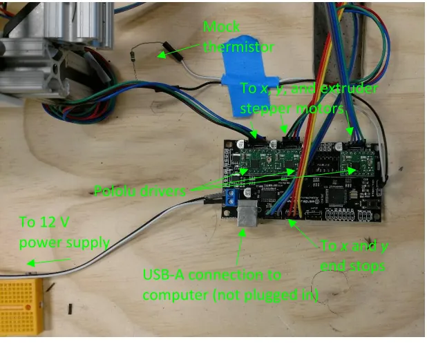
1.3B2 board and Polololu A4988 stepper motor drivers. Power is provided to the plotter by a
1 A, 12 V power supply. A resistor was connected to the thermistor pins on the board to
provide a constant temperature and satisfy an extruder temperature signal requirement. Figure
35 shows the configuration of the Sanguinololu board.
The hardware specifications of the silicone plotter can be seen in . The silicone plotter
has a print area of 640 mm × 600 mm. This allows for silicone infusion of large carbon fiber
fabric specimens. A cross was marked on the plywood under the glass bed to assist in centering
the fabric on the bed; the software automatically centers the model on the print bed. Before
running the plotter, mold release is applied to the glass bed so that the silicone will not stick to
the glass during curing. Once the glass bed surface is prepared, a slightly oversized piece of
carbon fiber fabric is taped to the bed using a 1.5-inch-wide painter’s tape as can be seen in
Figure 36. The painter’s tape serves as a ramp to prevent the extruder from catching on the
edge of the fabric which could move the fabric or misalign the extruder, and the carbon is
intentionally oversized so the extruder will not have to cross the tape threshold more than once
per print. A polytetrafluoroethylene (PTFE) O-ring was connected to the bottom of the syringe
To 12 V power supply
USB-A connection to computer (not plugged in) Pololu drivers
Mock thermistor
To x and y end stops To x, y, and extruder stepper motors
infuse the silicone into the carbon fiber fabric and served as a stabilization mechanism for the
top-heavy extruder assembly.
FIGURE 36. CARBON FIBER SAMPLE BEFORE SILICONE INFUSION USING PLOTTER
TABLE 2. HARDWARE SPECIFICATIONS OF PLOTTER
Print Area 640 mm × 600 mm
Resolution 23 µm
Nozzle Width 1.25 mm
Print Surface Glass
Compatible Materials Liquid resin systems
Firmware RepRap Sprinter
Communications USB
4.2 – Controlling the Plotter
In keeping with the accessibility of the plotter, all the software used to run the plotter is
open-source. The motherboard that controls the plotter is a Sanguinololu 1.3B2 board specifically
designed for use in 3D printers. Sanguinololu was chosen because it is an all-in-one solution
for the electronics and did not require electrical work beyond soldering the pins and connectors
onto the board. When combined with Pololu compatible stepper motor driver boards the
Sanguinololu can easily control the four axes of a 3D printer: x, y, z,and the extruder. For the
silicone plotter the z axis is ignored since it only infuses silicone into a flat carbon fiber fabric.
RepRap is a popular 3D printing solution known for its self-replicating capabilities.
The RepRap project is also a valuable source of information regarding 3D printing. The
firmware that controls the silicone plotter is Sprinter from the RepRap project. Sprinter was
chosen because it is simple but robust allowing for ease of use but also the freedom to make
the necessary modifications to adapt a 3D printing firmware to a large 2D silicone plotter.
Sprinter was configured to the specifications of the motherboard, stepper motors, and timing
belt hardware used in the silicone plotter project so the information received and signals sent
by the computer correspond to accurate real world movements. The configuration parameters
of the silicone plotter can easily be altered using the Arduino software and are found in
Appendix A.
Like 3D printers, the plotter uses G-code to control its movements. The firmware
the G-code to the plotter’s microcontroller to be executed. For the silicone plotter, Pronterface
was chosen as the host software because it is simple to use and provides an intuitive,
customizable graphical user interface. To generate the G-code to send to the printer it is
necessary to have a slicing software. Here, Slic3r was chosen for its ease of use. The Slic3r
configuration parameters were adjusted to match the silicone plotter hardware and can be found
in Appendix BAppendix B – Slic3r Configuration Bundle for Silicone Plotter. It is crucial to
have the same settings for the print area in both the host and slicing software otherwise the full
area of the bed will not be used. Like Sprinter, Pronterface and Slic3r are both open-source
software.
With the software infrastructure in place, infusing the silicone into the carbon fiber
fabric is very straightforward. Similarly to the hand fabrication methods, a pattern of the hinge
geometry must be created. Using any 3D CAD modeling software—SolidWorks was used in
this research—a three-dimensional model of the hinge geometry can be created and saved as
an .STL file, the same filetype as those used in 3D printing. By setting the model thickness to
that of a single layer as interpreted by the slicing software, in this case 0.3 mm, the plotter will
make a single infusion pass over the specified regions. Increasing the model thickness will
result in multiple infusion passes over the hinge regions. Once the .STL file of the hinge
geometry is created, it can be imported into the slicing software to be sliced then loaded into
the host software to be sent to the silicone plotter and plotted. The Slic3r and Pronterface
views of a Blintz origami hinge geometry to be plotted can be seen in Figure 38. The G-code
for the blintz model sliced and run in this test can be found in Appendix C.
4.3 – CNC Plotter Results
With the hardware and software of the silicone plotter operating smoothly, testing its
dual-matrix fabrication capabilities can begin. Initial tests were simple straight-line hinges to test
the infusion of the silicone through the fabric. As seen in Figure 39, the silicone beaded up on
top of the carbon fiber fabric and did not flow into it at all. It was also observed that degassing
the silicone using a vacuum chamber after mixing and before filling the syringe produced much
more consistent silicone output. The lack of through-thickness impregnation led to the
incorporation of the PTFE O-ring discussed previously. The O-ring applies pressure to the
silicone after it is laid down on the fabric by the syringe and impregnates it through the fabric.
With the O-ring providing adequate impregnation through the fabric, the amount of silicone
infused was altered to see how the changes would be reflected in the hinge regions. Hinges of
three different widths and three different thicknesses were modeled for a total of nine test hinge
templates, which can be seen in Table 3, to determine the parameters to use going forward.
The results of the width and thickness test can be seen in Figure 40. The silicone of the leftmost
test hinge was very sparse due to a small air pocket in the bottom of the syringe at the start of
the test. After this test, a small amount of silicone was extruded at the beginning of each test
similar in appearance to a barb that resulted from excess silicone buildup inside the O-ring
adapter that was dragged toward the start point of the next hinge line. The two- and
three-infusion passes (0.6 mm and 0.9 mm model thickness, respectively) hinges showed much more
consistency within the hinge than the single layer. However, the three-infusion pass yielded
much more material and spread it out to a much wider area than intended. Because of these
two factors, the two-infusion pass method was the one chosen to explore moving forward.
After further testing, a hinge width of 1.5 mm was chosen because it didn’t spread as
extensively as a 2 mm hinge and a 1 mm hinge experienced difficulty in the slicing software
when combined with multiple layers. With the hinge geometry determined, three simple hinge
samples were fabricated to compare the hand fabricated hinge to the plotted hinge and two
plotted hinges using different silicone systems, see Figure 41.
Hinge Thickness Corresponding Infusion Passes Hinge Width
0.3 mm 1
2 mm 3 mm 4 mm
0.6 mm 2
2 mm 3 mm 4 mm
0.9 mm 3
2 mm 3 mm 4 mm TABLE 3. TEST HINGE MODEL PARAMETERS
To demonstrate the plotter’s ability to easily fabricate more complex origami hinge
geometries, a blintz origami pattern was made using dual-matrix composites. The hinge
geometry can be seen in Figure 42, and the folding process can be seen in Figure 43. The
blintz pattern further demonstrates that it is possible to implement dual-matrix composites into
small-packing applications. The original blintz pattern was made with a 1.5 mm hinge, but it
didn’t fold perfectly flat in the final state, so it was remade using a 2.5 mm hinge. The plotter
took just over eight minutes to infuse the blintz geometry into the fabric, a process that would
FIGURE 41. SIMPLE HINGE SPECIMENS FOR TESTING
2.5 mm hinge blintz pattern folded more easily than the 1.5 mm hinge version, but it exhibited
fiber breakage within the hinges as seen in Figure 44 which implies that the epoxy resin was
able to permeate the hinge region where silicone should have been. It is suspected that the
O-ring infuser may be applying too much pressure and forcing the silicone out of the hinge
regions.
4.4 – Conclusions
A plotter was designed and constructed to infuse silicone hinges into carbon fiber for origami
architectures in dual-matrix composites. The plotter exhibits higher accuracy and repeatability
of hinge geometry than prior hand fabrication methods. Complex hinge geometries were
infused in a fraction of the time hand fabrication would allow. Further optimization is
necessary to ensure thorough impregnation of the fabric and eliminate excess silicone outside
hinge regions. With the plotter producing consistent composite parts, it is important to
determine the material properties of those parts to understand how they will behave before they
can be implemented into flight-worthy applications.
Chapter 5 – Mechanical Characterization of Dual-Matrix Composites
Mechanical characterization tests of dual-matrix composite coupons are developed to impart
near pure bending deformation. Loading in compression was applied using an Instron 8502
load frame equipped with a fixture designed to isolate bending and provide a large range of
motion of the bend. Three-dimensional digital image correlation (3D DIC) software was used
to capture the deformation of the sample during testing.
5.1 – Testing Setup
Testing was done using an Instron 8502 load frame and a 10 N load cell. Each sample was
loaded into a novel fixture designed to induce near pure bending. The fixture was developed
in concurrent work and applies a moment to the initially flat sample through an offset
compressive load, see Figure 45 and Figure 46 [22]. The test cycled each sample from nearly
flat to a 90° bend angle and back, twice. The test was started with the sample slightly
pre-buckled to prevent it from bending away from the cameras and into the fixture. The test was
stopped at 90° because past that point the weight of the fixture starts to influence the bending
and force measurements. The undeformed gauge length of the mounted sample was 50 mm
for each coupon. During the testing, the Instron load frame recorded the force information,
and knowing the force required to bend the sample and the geometry of the fixture allows for
calculation of the bending moment. Unlike single-matrix thin laminates, the curvature cannot
be accurately calculated using test parameters, so it must be obtained by other means. In this
research, 3D DIC was used to capture the deformation of the sample. The DIC setup consisted
of two 5 megapixel Point Grey Grasshopper2 cameras equipped with 67 mm lenses. The DIC
setup captured the deformation of the composite sample at one second intervals throughout the
test; the images captured were used to calculate the curvature using Vic-3D 7, see Figure 47.
Three dual-matrix composite samples previously fabricated were tested to determine
the bending stiffness of the materials. Two samples were fabricated using the Mold Star 30
silicone, one sample by hand and one with the plotter, to determine the difference, if any,
between the two manufacturing methods. The third sample was fabricated using the
were fabricated with the weave of the fabric in the 0-90° direction. The samples were speckled
using white spray paint by spraying paint over each sample and allowing paint droplets to fall
onto the surface of the sample. The speckle pattern allows the 3D DIC software to capture
information about the deformation of the sample. A base coat of paint was not applied because
it cracks and flakes off when the sample is subjected to the extreme bending. Each sample was
then cut into three coupons five inches wide. The coupons were individually mounted into the
fixture and loaded into the load frame, see Figure 46. Each coupon was bent prior to testing
to eliminate the effect of a stiffer first bend due to epoxy resin that wicks on top of and
underneath the silicone hinges during the vacuum bagging.
5.2 – Material Properties
Once the force data had been obtained from the test, the bending moment can be calculated
using the geometry of the fixture and sample and the following equations.
ℎ = 𝑔
2𝜃𝑠𝑖𝑛 𝜃 + 𝐿 cos(𝜃 + 𝛽)
𝑑 = 𝑔
2𝜃(1 − cos 𝜃) + 𝐿 sin (𝜃 + 𝛽)
𝑀 = (𝐹 −𝑤 4) 𝑑
By plotting the moment versus curvature and assigning a trendline, the bending stiffness of the
sample can be found in the slope of the line. The bending stiffness of each of the three test
coupons was found then three values were averaged to find a representative value for the
bending stiffness of each sample, see Table 4. Unlike the hand fabricated and plotted Mold
Star 30 samples (HMS30-1 and PMS30-1, respectively) the plotted Smooth-Sil 950 sample
(PSS950-1) only had two bending stiffness values to average. The sample was not pre-bent
before the speckle pattern was applied, so some of the speckle pattern was disrupted when the
epoxy cracked off the silicone. Because of this, the DIC system had difficulty tracking the
speckles and thus was unable to calculate the curvature of the hinge. The graphs of moment
versus curvature for each sample can be seen in FIGS. The values are negative because of
moment conventions and how the DIC software defines curvature. All the samples returned
to a completely un-bent state after being removed from the test fixture.
Sample Bending Stiffness [N mm2]
Test 1 Test 2 Test 3 Sample Average
HMS30-1 0.9382 0.8299 0.9496 0.9059
PMS30-1 0.7972 1.8123 0.8591 1.1562
PSS950-1 1.0758 1.2386 - 1.1572
FIGURE 49. MOMENT VS.CURVATURE OF PLOTTED MOLD STAR 30 SAMPLE (SOLID LOADING, DASHED UNLOADING)
5.3 – Discussion
From the results of the bending tests, it can be seen that the Smooth-Sil 950 hinge is stiffer
than the Mold Star 30 hinges. This is expected as the Smooth-Sil 950 is much stiffer than the
Mold Star 30, see Table 1. Additionally, the higher tear strength of the Smooth-Sil 950
prevents the silicone from being pulled away from the carbon fiber reinforcement as easily as
the Mold Star 30, which could be an important consideration for deployable structure
applications. The comparison between the hand fabricated and plotted Mold Star 30 samples
is less clear, however. The average bending stiffness suggests that the plotted sample is stiffer
than the hand fabricated sample, but it is difficult to make this conclusion since one coupon
test yielded a significantly higher stiffness than the other two. If that data point is removed
from the calculation of the average, the plotted sample appears to be less stiff. This implies
that either one part of the sample was much stiffer than the others because of epoxy incursion
into the hinge or there was a flaw in that particular test. Either way, it is necessary to conduct
more tests to increase the accuracy of the results.
The stiffer hinges produced by the Smooth-Sil 950 result in higher strain energy storage
within the composite than the Mold Star 30 hinges. Strain energy storage would be an
important factor to consider when incorporating dual-matrix composites into self-deploying
structures. For very large deployable structures or those deploying another mass, the energy
required to fully deploy the structure would be higher than smaller, lighter structures. The
hyperelastic matrix chosen for the hinges could allow for tuning of the strain energy storage
depending on the application of the composite.
For some of the samples tested, Vic-3D 7 lost sight of the speckle pattern during certain
parts of the test and therefore was unable to calculate the curvature across the entire hinge
region. Coupon 3 from the PSS950-1 sample was the most severely affected to the point that
there was not enough curvature data to calculate any information regarding bending stiffness.
Further testing is required to increase sample size and improve the accuracy of the material
remain in the camera’s focus and the speckle pattern is able to be tracked throughout the
duration of the test.
5.4 – Conclusions
Dual-matrix composite samples were tested using a novel bending fixture that allows for a
large range of motion of highly flexible composites and application of a near pure bending
moment. Using compressive data from the load frame and deformation captured by 3D DIC
the bending stiffness of the composite hinges was calculated. A stiffer matrix in the hinge
region results in a higher bending stiffness, but it is still unclear if the fabrication method
influences the bending stiffness of a simple hinge as well. Further testing is required to
Chapter 6 – Conclusions
6.1 – Dual-Matrix Composite Origami
Methods of infusing silicone through a two-step process to create discrete regions flexible and
stiff matrices was explored and applied to complex origami hinge architectures. By bounding
off hinge regions, infusing a flexible silicone matrix, and allowing it to cure before finally
infusing a stiff matrix, structures with highly localized flexible hinges could be made. Several
different traditional and modern origami designs from were fabricated to prove that
dual-matrix composites can be implemented as structures with complex folding geometries. These
fabrication techniques can be applied to manufacture lightweight, self-deploying structures
such as booms and panels as well as high-performance mechanical metamaterials. However,
the hand fabrication techniques were deemed too inconsistent and nonrepeatable to meet the
demands of high accuracy and precision of the hinges of these complex structures, and a
computer controlled solution was explored.
6.2 – CNC Plotter for Dual-Matrix Composites
A computer numerical control plotter was developed to meet the needs of dual-matrix
composite fabrication. Computerized modeling of the hinge architectures and control of the
silicone infusion process addresses the flaws exhibited by the hand fabrication methods by
increasing both accuracy and repeatability of infusion. The plotter also greatly reduced both
the material waste generated by the fabrication process and the infusion setup time by
eliminating the need for the hinge bounding process. Origami hinge geometries were infused,
and the resulting composites were folded into their alternate configurations. The plotter shows
promise as a method to consistently produce the accurate hinge geometries required by highly
complex origami deployable structures and mechanical metamaterials. The modular design of
the plotter provides room for expansion as well as implementation of other flexible matrix
![FIGURE 1. DLR’S OMEGA BOOM HALF-SHELL AND COILED FULL BOOM [4]](https://thumb-us.123doks.com/thumbv2/123dok_us/1449780.1177603/14.612.90.542.489.644/figure-dlr-omega-boom-half-shell-coiled-boom.webp)
![FIGURE 3. FIBER MICROBUCKLING IN A SOFT-MATRIX COMPOSITE [6]](https://thumb-us.123doks.com/thumbv2/123dok_us/1449780.1177603/15.612.96.541.413.539/figure-fiber-microbuckling-soft-matrix-composite.webp)
![FIGURE 8. POTENTIAL ORIGAMI MORPHING RADIATOR DESIGNS [13]](https://thumb-us.123doks.com/thumbv2/123dok_us/1449780.1177603/21.612.148.484.159.399/figure-potential-origami-morphing-radiator-designs.webp)