Ant Based Routing and QoS Effective Data
Collection for Mobile Wireless Sensor
Network
L.Poongodi*1, Dr.M.Namasivayam*3
Research Scholar, Mahendra Arts and Science College, Kalipatti, Namakkal (Dt), Tamilnadu, India*1
Head of the Department (DCS), Mahendra Arts and Science College, Kalipatti, Namakkal (Dt), Tamilnadu, India*2
Asst. Professor, Department of Computer Science, Mahendra Arts and Science College, Kalipatti, Namakkal
(Dt),Tamilnadu, India*3
ABSTRACT: Mobility management in Mobile Wireless Sensor Networks (MWSNs) is a complex problem that must be taken into account. In MWSN, nodes move in and out of the network randomly. Hence, a path formed between two distant nodes is highly susceptible to changes due to unpredictable node movement. Also, due to the limited resources in WSN, the paths used for data transmission must be tested for the link quality and time consumed for data forwarding. In order to solve these issues, in this paper, an Ant based routing protocol with QoS effective data collection mechanism is proposed. In this protocol, the link quality and link delay are estimated for each pair of nodes. Link quality is estimated in terms of Packet Reception Rate (PRR), Received Signal Strength Indicator (RSSI) and Link Quality Index (LQI). A reliable path is chosen from the source to the destination based on the paths traversed by forward ants and backward ants. Then, if the link is found to be defective during data transmission, a link reinforcement technique is used to deliver the data packet at the destination successfully. The mobile robots collect the information with high data utility. In addition each mobile robot is equipped with multiple antennas and Space Division Multiple Access (SDMA) technique is then applied foreffective data collection from multiple mobile robots. Simulation results show that the proposed routing protocol provides reliability by reducing the packet drop and end-to-end delay when compared to existing protocols.
I. INTRODUCTION
A Wireless Sensor Network (WSN) consists of several minute sensor nodes which perform functions like monitoring the network surrounding, handling the sensed information, communicating with the destination node wirelessly, etc. The sensor nodes in WSN have limited resources and are basically microelectronic devices. After the deployment of the sensors in WSN, these sensors work independently using batteries with limited energy. Hence, operations such as routing, duty cycle scheduling and medium access controlling must be performed efficiently in WSN [5,10]. WSN can be used in home, military, science, transportation, health care, disaster relief, warfare, security, industrial and building automation, space discovery, etc. WSN is vastly used in phenomena monitoring [8].
Recently, mobile wireless sensor networks (MWSNs) are emerging as a new trend of WSN. They posses all the properties of static WSNs along with node mobility [15]. A major problem in mobile wireless sensor networks (i.e. designed for data-gathering rather than for peer-to-peer sharing) is assessing the 'best' path that a message should take for eventual delivery to a base-station or exit point from the network. Thus delivery is undertaken in a store and forward manner, with nodes exchanging packets on contact with one another. If the mobility patterns of nodes are highly dynamic and essentially unpredictable, determining the optimal path is impossible [3].
Node mobility brings several challenges to large-scale sensor networking.
The preconstruction of message delivery network may not be useful since the topology may change too frequently
The frequent location updates from a mobile node can lead to an excessive drain of limited battery power of sensors and increased collisions in wireless transmissions.
The situation can get worse when the number of mobile nodes grows.
Self Configuration: Once deployed in an unknown area, mobile sensor nodes should configure to cover the area. Agility: As the phenomena of interest expand, shrink, or migrate to other places, MSN should adjust to the change
of the dynamic sensing environment to maximize the sensing coverage.
Network Connectivity: MSNs should have access to a base station to report the current sensing readings. If only a subset of nodes have direct connectivity to the base station, the rest of nodes should have multi-hop paths to those that have that capability.
Energy Efficiency: Energy efficiency is critical to lengthen the network lifetime. Therefore, the traveling distance of mobile nodes and the communication overhead should be minimized.
Noise Tolerance: The sensing environment is subject to a high level of spatial and temporal noise as well as the sensor reading error. Regardless, the MSN should be able to find the optimal location of deployment [12].
Routing in MWSN is very challenging due to its constantly varying topology and regular link failures. Link failure causes delay in packet delivery and may also lead to packet loss. Thus, energy usage increases. Most of the ad hoc routing protocols such as Ad hoc On-Demand Distance Vector (AODV) Routing and On Demand Multi path Distance Vector Routing (AOMDV) perform effectively in traditional networks, however these protocols work in a poor way in WSN since the resources are limited in the network nodes. Also, the recovery techniques used to overcome the repeated link failures consume high energy. The conventional routing protocols of mobile ad hoc networks like AODV, DSR, OLSR, LAR, etc and energy-conserving protocols can be used for WSN. But, the continuous mobility is not taken into account as a network characteristic by these protocols for deciding the links to forward the data packets. So in this paper, we propose to develop a routing technique which considers the node movement [6].
In this paper, ant based routing protocol along with QoS effective data collection is proposed using Ant Colony Optimization (ACO) algorithm is proposed.
II. LITERATURE REVIEW
Getsy S Sara et al [1] have developed a hybrid multipath routing algorithm with an efficient clustering mechanism. A node with higher amount of energy, good communication range and minimum mobility is chosen as the cluster head. The energy consumption during routing is handled efficiently by including the Energy Aware (EA) selection scheme and the Maximal Nodal Surplus Energy determination scheme in this paper. This proposed technique includes the clustering and routing protocol which performs well in highly dynamic environment and also in energy lacking network conditions.
Karim and Nasser [2] have presented a location-aware and fault tolerant clustering protocol for mobile WSN (LFCP-MWSN). At the time of cluster formation and movement of nodes between two clusters, the nodes are localized by the LFCP-MWSN technique by adding a range free mechanism. The energy consumed by this protocol is around 30% lesser when compared with the conventional protocols. The end to end transmission delay involved with this protocol is also low.
SamerAwwad et al [3] have proposed a technique in which the cluster head accepts the data packet from all the nodes in the network during the time slot assigned by TDMA. During free time slots, if a node enter a cluster, then every cluster head behaves like free cluster head one after the other. Based on the traffic as well as mobility features of the network, the TDMA scheduling is changed accordingly by the CBR Mobile WSN. The protocol transmits the data towards the cluster head on the basis of the received signal strength.
Peng Li et al [4] have proposed a cluster-based data collection algorithm ECDGA for mobile wireless sensor networks. This network is made up of both mobile nodes as well as static nodes. The mobile nodes form a cluster by self systemizing process which adjusts its position according to the distance between the static nodes. The cluster head is selected by the static nodes on the basis of the residual energy and mobile node position, which is important in transferring the data packet within the cluster. Data gathering as well as data fusion is the task of cluster head. This algorithm enhances the network lifetime and the network reliability.
the basis of the MoX MAC protocol and the reduction of the static nodes in the network due to the presence of the mobile nodes is also handled.
Duc Van Le et al [6] have proposed an ad hoc routing and relaying architecture called as Robots’ Controllable Mobility Aided Routing (RoCoMAR). This routing is performed according to the robotic nodes controllable mobility. After the task is achieved or if there is no more use from the relay, then the robotic node stops functioning for the relay. When the relay position is determined, the robotic node places itself at a position by adjusting to the mobility of the network nodes to maintain the link.
YongpingXiong et al. [11] have proposed a data harvesting scheme for intermittently connecting mobile sensor network. Their approach took full advantage of storage resource and mobility pattern knowledge to improve the delivery ratio while minimizing the transmission overhead.Furthermore, their robust approach could be adaptive to the dynamic topology of network. An efficient forwarding mechanism and intelligent buffer management strategy were presented by them to route the data from mobile sensors towards a number of fixed or mobile sinks. In their scheme, every sensor was associated with a parameter delivery utility which signified the likelihood that it could deliver a message to a sink. Also a message was forwarded in their scheme according to random or utility-based strategy depending on whether the mobility pattern could be predicted to a certain extent.
FarshidHassaniBijarbooneh et al [13] have presented a novel quality-of-information (QoI) aware data collection protocol (QoIACP) for wireless sensor networks with mobile users. The protocol is designed to optimize data utility, which measures the normalized QoI value of collected data per transmission. A hybrid methodology is used in our QoIACP protocol with a distributed neighborhood discovery protocol, but centralized clustering and data collection scheduling for coordination among multiple mobile users. The algorithm can significantly improve data utility at low communication overhead. However the sensors in QoIACP may have slightly higher communication overhead.
Yosef Alayev et al [14] have proposed to study a variant of TMP problem with adaptive transmission power and rate control. They have formulated the problem for joint scheduling with either power control or rate control or both. The data items are to be transmitted to mobile clients via the stationary data access points (APs). The scheduler dedicates sequences of consecutive timeslots of an AP to downloading a data item to a client. The APs controlled transmission power to tune its transmission range making sure that no interference occurs with neighbouring APs' transmissions. However if two machine may interfere with one another the power levels and their transmission rates may change.
AndreyKoucheryavy and Ahmed Salim [15] have presented a prediction based clustering algorithm for MWSNs. It applies necessary conditions for cluster-head election along with heuristic predictors to generate steady and balanced clusters.
III. ANT BASED ROUTING AND QOS EFFECTIVE DATA COLLECTION MECHANISM
A.Ant Colony Optimization
Ant Colony Optimization (ACO) is a class of algorithms whose first member is called Ant System. When the insects like ants, bees etc., acting as a community, even with very limited individual capability can cooperatively perform many complex tasks necessary for their survival. This new heuristic is robust and versatile in handling a wide range of combinatorial optimization problems [84]. Here, the Forward Ant agent (FA) establishes the pheromone track to the source node whereas the Backward Ant agent (BA) establishes the pheromone track to the destination node.
Figure-1 Foraging Behavior of Ants
Once all ants have computed their tour, Ant System updates the pheromone trail using all the solutions produced by the ant colony. Each edge belonging to one of the computed solutions is modified by an amount of pheromone proportional to its solution value. At the end of this phase, the pheromone of the entire system evaporates and the process of construction and update is iterated.
The functions of an ACO algorithm can be summarized as follows:
A set of computational concurrent and asynchronous agents (a colony of ants) moves through states of the problem
corresponding to partial solutions of the problem to solve.
They move by applying a stochastic local decision policy based on two parameters, called trails and attractiveness.
By moving, each ant incrementally constructs a solution to the problem.
When an ant completes a solution, or during the construction phase, the ant evaluates the solution and modifies the
trail value on the components used in its solution.
This pheromone information will direct the search of the future ants.
The algorithm is summarized as follows: 1. {Initialization}
Initialize τιψ and ηιψ, V(ιψ). 2. {Construction}
For each ant k (currently in state ι) do repeat
choose in probability the state to move into append the chosen move to the k-th ant's set tabu k. until ant k has completed its solution.
end for 3. {Trail update}
For each ant move (ιψ) do computeΔτιψ
update the trail matrix. end for
4. {Terminating condition}
If not (end test) go to step 2
B.Proposed Contributions
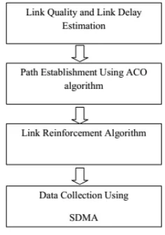
The mobile robots collect the information with high data utility [16] .In addition we equip each mobile robot with multiple antennas and apply SDMA (Space Division Multiple Access) technique to data gathering [17] from multiple mobile robots. SDMA schedules data transmissions effectively so that we can minimize the total data gathering time by exploring the tradeoff between shortest moving tour of mobile robots and full utilization of SDMA.
Figure 2: Block Diagram
C.Link Quality and Link Delay Estimation
The link quality is estimated in terms of Packet Reception Rate (PRR), Received Signal Strength Indicator (RSSI) and Link Quality Index (LQI) [7]. The LQI is estimated according to the equation (1) given below:
= × ( ) (1)
where ( ) = + (2)
∈[−100,−40]
( ) ∈[0,1]
∈[0,1]
The link delay, is calculated according to equation (3) given below:
= + (3)
where is the processing delay involved with the forward ant/ backward ant
is the propagation delay between two nodes
D.Path Establishment for Mobile Robots using ACO algorithm
The path to transmit the data between the source and the destination is determined using the ACO algorithm. When there is need to transmit data, the ant colony is used to discover all the possible paths towards the destination using forward ants and backward ants. The format of the forward ant and backward ant is described in figure (2) and (3).
Table-1 Format of Forward Ant Source
Address
Destination Address
Intermediate Nodes
LQI value
Table-2: Format of Backward Ant Source
Address
Destination Address
Intermediate Nodes
LQI value
Link Delay
These ants use pheromone to identify the path travelled. The forward ants distribute pheromone as it travels towards the destination. The pheromone aids the forward node to select links with lower delay and connect to nodes with good LQI. After the forward ants reach the destination, backward ant is created which traverse back to the source. The backward ants use the information recorded and pheromone distributed by the forward node to reach the source. The pheromone, redistributed by backward node is given according to the equation (4) depicted below:
= + − (ms) (4)
Based on the LQI value and time used, the path is selected. The ACO technique is described in algorithm 1. Algorithm 1
Notations:
1. S : Source
2. D : Destination
3. LQI : Link Quality Index
4. : Link Delay
5. : Forward Ant
6. : Backward Ant
1. When S wants to transmit data to D, it launches the towards the D.
2. The move towards D through intermediate 1hop nodes.
3. The calculate the LQI value for every path towards all the 1 hop nodes according to equation (1).
4. The 1hop nodes with path having higher LQI value are selected and as it passes a node, it distributes
pheromone at the node.
5. As the passes each link, the link delay is estimated according to equation (3).
6. The intermediate node details, link delay and the LQI value of every node traversed by the are
recorded by it.
7. When the reach D, are created by D.
8. The move towards the source by traversing the path selected by the .
9. During the backward travel, the distribute the pheromone at all the traversed node and records the link
delay.
10. When the reach S, the S considers the path with best LQI value and lower link delay to transmit
the data packet.
Thus, the path from the source to the destination node is determined based on the ACO algorithm which considers the quality of every link used for data transmission. Also, the selected path ensures lower delay in forwarding packets.
E.Link Quality Reinforcement algorithm
Link Quality reinforcement is performed to reinforce the link defects. This is necessary even though the path is determined efficiently using ACO due to the error prone nature of the wireless sensor network. Due to the dynamic network topology, there are possibilities of link compromise. So, link quality reinforcement is used.
Algorithm 2 Notations:
1. S : Source node
2. D : Destination node
3. ACO : Ant Colony Optimization
4. LQI : Link Quality Index
5. : End To End LQI
6. : required LQI
7. : Reinforcement Request
8. : Reinforcement Node
9. : Reinforcement Reply
10. : Robotic Node
11. : Move Request
12. : Predecessor node
13. _ℎ : Next Hop Change
1. After the path is determined using the ACO algorithm, source transmits the data to the first intermediate
node in the path.
2. When the intermediate node receives the data packet, it estimates the LQI and appends it at the
packet header along with the LQI values of the previous nodes across the path.
3. On receiving the data packet, D retrieves the LQI value at every link and estimates the .
4. D compares the estimated with the predefined .
5. If > then, link quality is good.
6. If < then, link quality is poor.
7. When the link quality is poor, D sends a to the node with lower LQI and it is considered as
.
8. On receiving a ,the responds by sending an ACK to D to confirm the request reception.
9. If D receives the ACK, then it waits for .
10. If D doesn’t receive ACK within a predefined time interval, then it retransmits the .
11. After sending an ACK to D, the searches for a in its neighborhood and sends a to the
closest .
12. On receiving the which consists of the address of the , the sends an ACK to the
.
13. Then the moves towards the assigned location and locates itself at the midpoint between the
and .
14. updates its routing table with its predecessor node as and its successor node as .
15. then sends a _ℎ message to the , to update its routing table with its successor
node as .
16. Now the data packet is forwarded by the to the ,which in turn forwards the data packet to
the .
17. On receiving the data packet from the , the sends a to D to confirm the
successful formation of a relay.
Thus, the robotic nodes are included in all the links with poor quality until the data is delivered at the destination. This increases the LQI value and thus stabilizes the path used for data transmission. So, data is delivered at the destination reliably.
F.Estimating Data Utility (Du)
Data Utility [16] is a metric estimating the sum of qualities of information from the sensed data divided by communication overhead occurring the network in during data collection. Moreover, it maximizes gathered information without any increase in energy consumption.
In Algorithm 3, the process of collecting the data with high data utility is described. Algorithm 3
Notations:
1. : Sensor node
2. : mobile robot
3. i : integer value
4. ( , ) : data utility for communication between and
5. ( ) : Data size that is buffered at
6. ( ) : Data quality at node
7. ( , ) : Boolean Variable
8. ( , ) : number of hops between and m
1. Every sensor node maintains two neighbor node sets; one its immediate neighbor nodes which is considered as the
candidate sink nodes and the second node set is the immediate neighbor of its previous node.
2. When in the sensing field, if the candidate sink node in the node set of the sensor node differs from the candidate
sink node of the previous sensor node set, then the current sensor node requests its candidate sink node for a neighborhood discovery process
3. In the neighborhood discovery process, the sink node broadcasts a message to the immediate neighbors.
4. The broadcasts message includes information such as node address, data size in the buffer, and data quality.
5. The sensor nodes receiving the broadcast message responds by providing its information to the requesting node.
6. Based on the received information, the candidate node ananlyzes the surrounding sensor node’s locations.
7. Then a cluster of sensor nodes is formed by considering the nodes with high data utility value.
8. The data utiliy value is estimated by the mobile robot according to (5) :
( , ) = ( ). ( ). (( , )
(( , ) (5)
9. The sensor with higher data utility value is selected as the data collecting point by the mobile robots.
10. In this way, a cluster of sensor nodes are formed with high data quality.
Thus, all the sensor nodes with higher data quality are selected by the mobile robots for better network performance.
G.Data Collection using Space Division Multiple Access (SDMA)
Algorithm-4 Notations:
1. P : set of subsets of polling points
2. : subset of polling points
3. : sensor nodes
4. : integer value
1. The polling points in the network are selected and grouped according to its current region, into a set of subsets of P
denoted by , ,….., , such that
∩ ∩… …∩ = ∅
∪ ∪… …∪ =
2. The sensor nodes in the network are grouped according to its current location and represented by , ,….., ,
such that
∩ ∩… …∩ = ∅
∪ ∪… …∪ =
3. The mobile robots visit the polling points in the sequence where i=1, 2 ….., n, such that maximum data gathering time among n regions is minimized.
4. Thus, the overall latency involved in data collection from the sensor nodes is minimized.
5. Then the compatible pair among sensors are determined by connecting two sensors which lie within the coverage
6. The polling point ensures that the compatible pair of sensors are in a short moving tour. 7. If the sensor pair does not lie within the short moving tour path, then this pair is ignored. 8. This guarantees the latency involved in data uploading to be maintained at a minimum level.
9. By connecting all the polling points, a minimum spanning tree is created and values are allocated to each point of the tree. 10. Then the spanning tree is divided into smaller trees, since the network range is usually too large to be considered a single tree. 11. After the tree size is optimized, the mobile robots traverse through the tree.
12. The mobile robots hop from one polling point to the next polling point, along the tree path.
13. At each polling point, the mobile robot collects data from every compatible sensor pair within the coverage area of the polling point.
14. After gathering data from one polling point, the mobile robot hops to the next polling point and so on.
IV.SIMULATIONRESULTS
A. Simulation Parameters
We use NS-2 [16] to simulate our proposed Ant based Routing and QoS Effective Data Collection (ARQEDE) protocol. We use the IEEE 802.11 for Mobile Sensor Networks as the MAC layer protocol. It has the functionality to notify the network layer about link breakage. The sensor nodes are randomly deployed over an area of size 500 meter x 500 meter. In the simulated topology, there are 5 mobile robotic nodes and 95 mobile sensors with one static sink or base station, located at the top right corner. The mobile sensors are moving at an average speed of 2m/s and the mobile robots are moving at the speed of 5m/s.
The performance of AMAR is compared with RoCoMAR [6] and MoXMAC protocols and the performance is evaluated in terms of average packet drop, packet delivery ratio, end-to-end delay, average residual energy and routing overhead.
The simulation settings and parameters are summarized in table 1
Table 1: Simulation parameters Total number
of Nodes 101
Number of
Robotic nodes 5
Speed of
mobile sensors
2 m/s
Speed of
robotic nodes 5 m/s
Area size 500 X 500m
MAC 802.11
Simulation
Time 50 sec
Traffic Source CBR
Data sending Rate
50,100,150,200 and 250Kb
Number of
flows 2 to 10
Propagation TwoRayGround
Antenna OmniAntenna
Initial Energy 20.1J
Transmission
Power 0.660
Receiving
B. Results & Analysis
In this section, the performance evaluation of AMAR and RoCoMAR protocols are presented by varying the data sending rate and number of traffic flows.
1. Varying Data Sending Rate
The data sending rate of CBR traffic is varied from 50 to 250Kb for 10 traffic flows and the performance is evaluated.
Fig 4: Rate Vs Delay
Figure 4 shows the resutls of delay for ARQEDE,MoXMAC and RoCoMAR protocols, when the rate is varied. Since ARQEDE includes the link delay metric also in path establishment, the associated delay of ARQEDE is 73% lesser when compared to RoCoMAR and ARQEDE is 64% leser when compared to MoXMAC.
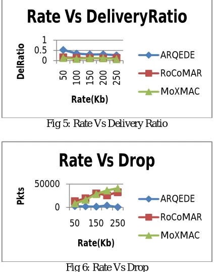
Fig 5: Rate Vs Delivery Ratio
Fig 6: Rate Vs Drop
Figure 5 and 6 show the resutls of packet delivery ratio and packet drop for ARQEDE ,MoXMAC and RoCoMAR protocols, when the rate is varied. As the volume of data traffic increases, there will be more packet drops. As depicted in figure 5 and 6, the packet drop linearly increases for RoCoMAR at higher data rates whereas ARQEDE shows a
0 10 20 5 0 1 0 0 1 5 0 2 0 0 2 5 0 D El ay (S e c) Rate(Kb)
Rate Vs Delay
ARQEDE RoCoMAR MoXMAC 0 0.51 5 0 1 0 0 1 5 0 2 0 0 2 5 0 D el R a ti o Rate(Kb)
Rate Vs DeliveryRatio
ARQEDE
RoCoMAR
MoXMAC
0 50000
50 150 250
P
kt
s
Rate(Kb)
Rate Vs Drop
ARQEDE
RoCoMAR
steady packet drop and delivery ratio. Accurate estimation of link quality in ARQEDE yields 63% higher delivery ratio and 90% lesser packet drops, when compared to RoCoMAR and ARQEDE is 70% is higher delivery ratio than MoXMAC and ARQEDE is 88% lesser packet drops.
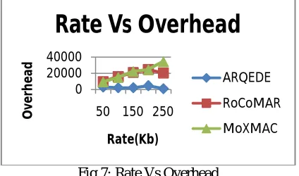
Fig 7: Rate Vs Overhead
Figure 7 shows the results of overhead occurred for ARQEDE,MoXMAC and RoCoMAR protocols, when the data sending rate is varied. The use of ACO technique in ARQEDE reduces the huge packet exchange involved in route discovery. Hence the overhead of ARQEDE is 84% less, when compared to RoCoMAR and 85% less,when compared to MoXMAC.
Fig 8: Rate Vs Residual Energy
Figure 8 show the results of residual energy for ARQEDE and RoCoMAR protocols, when the rate is varied. When comparing the performance of the two protocols, we infer that ARQEDE has 21% higher residual energy, than RoCoMAR, since the number of route disconnections is minimized in ARQEDE there by reducing the energy involved in retransmission and 18% higher residual energy then MoXMAC.
2. Varying the Data Flows
The number of sources sending data to the sink are varied from 2 to 10 with a data sending rate of 50Kb and the performance is evaluated.
0 20000 40000
50 150 250
O
ve
rh
ea
d
Rate(Kb)
Rate Vs Overhead
ARQEDE
RoCoMAR
MoXMAC
0 50
En
er
gy
(J
)
Rate(Kb)
Rate Vs
ResidualEnergy
ARQEDE
RoCoMAR
Fig 9: Flows Vs Delay
Figure 4 shows the resutls of delay for ARQEDE,MoXMAC and RoCoMAR protocols, when the rate is varied. Since ARQEDE includes the link delay metric also in path establishment, the associated delay of ARQEDE is 63% lesser when compared to RoCoMAR and ARQEDE is 64% leser when compared to MoXMAC.
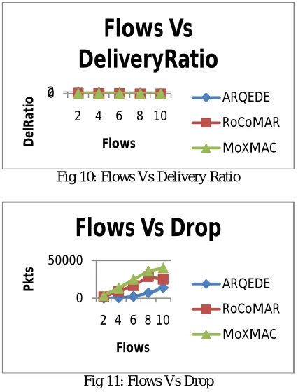
Fig 10: Flows Vs Delivery Ratio
Fig 11: Flows Vs Drop
Figure 10 and 11 show the resutls of packet delivery ratio and packet drop for AMAR and RoCoMAR protocols, when the data flows are varied. As the volume of data traffic increases, there will be more packet drops. As depicted in figure 5, the packet drop linearly increases for RoCoMAR and AMAR when the data flows are increased. Accurate estimation of link quality in AMAR yields 60% higher delivery ratio and 67% lesser packet drops, when compared to RoCoMAR.
0 20 40
2 4 6 8 10
D
el
a
y(
Se
c)
Flows
Flows Vs Delay
ARQEDE
RoCoMAR
MoXMAC
0 2
2 4 6 8 10
D
e
lR
at
io
Flows
Flows Vs
DeliveryRatio
ARQEDE
RoCoMAR
MoXMAC
0 50000
2 4 6 8 10
P
kt
s
Flows
Flows Vs Drop
ARQEDE
RoCoMAR
Fig 12: Flows Vs Overhead
Figure 12 shows the results of overhead occurred for ARQEDE,MoXMAC and RoCoMAR protocols, when the data sending rate is varied. The use of ACO technique in ARQEDE reduces the huge packet exchange involved in route discovery. Hence the overhead of ARQEDE is 46% less, when compared to RoCoMAR and 68% less,when compared to MoXMAC.
Fig 13: Flows Vs Residual Energy
Figure 13 show the results of residual energy for ARQEDE and RoCoMAR protocols, when the rate is varied. When comparing the performance of the two protocols, we infer that ARQEDE has 14% higher residual energy, than RoCoMAR, since the number of route disconnections is minimized in ARQEDE there by reducing the energy involved in retransmission and 17% higher residual energy then MoXMAC.
V. CONCLUSION
In this paper, we have proposed ant based mobility aided routing in the wireless sensor network. Initially, the ant colony optimization technique is used to determine a reliable path. The forward ants and the backward ants use pheromone to avoid revisiting any node which may prolong the path. The link quality and delay involved are the important factors used for path selection by the ant colony. After the selection of a path, data packets are transmitted by the source towards the destination node. During data transmission, the link quality is again tested and compared with respect to a predefined value. If the link quality is determined to be poor then robotic nodes are placed in the poor link in between the two consecutive intermediate nodes. This enhances the link quality and makes the link reliable. The data is then delivered at the destination by inserting robotic nodes whenever any link quality is determined to be poor. For QoS effective data collection, each mobile robot is equipped with multiple antennas to apply SDMA technique to collect data with high utility. Simulation results show that the proposed routing protocol provides reliability by reducing the packet drop and end-to-end delay when compared to existing protocols.
0 20000 40000
2 4 6 8 10
O
ve
rh
e
ad
Flows
Flows Vs Overhead
ARQEDE
RoCoMAR
MoXMAC
0 20
2 4 6 8 10
En
e
rg
y(
J)
Flows
Flows Vs
ResidualEnergy
ARQEDE
RoCoMAR
REFERENCES
[1]. Getsy Sara, Kalaiarasi, NeelavathyPari and Sridharan, "Energy Efficient Clustering And Routing in Mobile Wireless Sensor Network,"
International Journal of Wireless & Mobile Networks, Vol.2, No.4, 2010
[2]. L. Karim and N. Nasser, "Reliable location-aware routing protocol for mobile wireless sensor network," The Institution of Engineering and
Technology, 2012
[3]. Samer A. B. Awwad, Chee K. Ng, Nor K. Noordin, and Mohd. Fadlee A. Rasid, "Cluster Based Routing Protocol for Mobile Nodes in Wireless
Sensor Network," IEEE, 2009
[4]. Peng Li and XuJian-bo, "ECDGA: An energy-efficient cluster-based data gathering algorithm for Mobile Wireless Sensor Networks," IEEE
International Conference of Computational Intelligence and Software Engineering, 2009.
[5]. Papa Dame Ba, IbrahimaNiang and BambaGueye, "An optimized and power savings protocol for mobility energy-aware in wireless sensor
networks," Springer, Telecommunication System, 2013
[6]. Duc Van Le, Hoon Oh and Seokhoon Yoon, "RoCoMAR: Robots’ Controllable Mobility Aided Routing and Relay Architecture for Mobile
Sensor Networks," Sensors, 2013
[7]. Michele Rondinone, Junaid Ansari, JanneRiihijarvi and Petri Mahonen, "Designing a Reliable and Stable Link Quality Metric for Wireless
Sensor Networks, "Proceedings of the workshop on Real-world wireless sensor networks, ACM, 2008
[8]. Xing Zhang, Jingsha He and Qian Wei, "Energy-Efficient Routing for Mobility Scenarios in Wireless Sensor Networks," In Proceedings of the
Third International Symposium on Electronic Commerce and Security Workshops, 2010
[9]. Shahzad Ali and SajjadMadani, "Distributed Efficient Multi Hop Clustering Protocol for Mobile Sensor Networks,"The International Arab
Journal of Information Technology, Vol. 8, No. 3, 2011
[10].Kai Li and Kien A. Hua, "Mobility-assisted Distributed Sensor Clustering for Energy efficient Wireless Sensor Networks," Ad Hoc and Sensor
Networking Symposium, 2013.
[11].YongpingXiong, JianweiNiu, Jian Ma and Limin Sun, “Efficient Data Delivery in Mobile Sensor Networks”, Journal of Communication and
Computer, ISSN 1548-7709, Volume 7, No.5 (Serial No.66), USA, May 2010.
[12].Seokhoon Yoon, OnurSoysal, Murat Demirbas, and ChunmingQiao, “Coordinated Locomotion of Mobile Sensor Networks”, 5th Annual IEEE
Communications Society Conference on Sensor, Mesh and Ad Hoc Communications and Networks, SECON '08, San Francisco, CA, 16-20 June,2008.
[13].FarshidHassaniBijarbooneh, Pierre Flener, Edith Ngai, and Justin Pearson, “Optimizing Quality of Information in Data Collection for Mobile
Sensor Networks”, Quality of Service (IWQoS), 2013 IEEE/ACM 21st International Symposium on IEEE 2013.
[14].Yosef Alayev, Fangfei Chen, Yun Hou, Matthew P. Johnson, Amotz Bar-Noy, “Throughput Maximization in Mobile WSN Scheduling With
Power Control and Rate Selection”, IEEE Transactions on Wireless Communications, Vol. 13, No. 7, Pages: 4066-4079, July 2014.
[15].AndreyKoucheryavy and Ahmed Salim, “Prediction-based Clustering Algorithm for Mobile Wireless Sensor Networks”,
[16].FarshidHassaniBijarbooneh, Pierre Flener, Edith Ngai, and Justin Pearson, “Optimising Quality of Information in Data Collection for Mobile
Sensor Networks”, Quality of Service (IWQoS), 2013 IEEE/ACM 21st International Symposium on IEEE 2013.
[17].Miao Zhao, Ming Ma and Yuanyuan Yang, “Efficient Data Gathering with Mobile Collectors and Space-Division Multiple Access Technique
in Wireless Sensor Networks”, IEEE TRANSACTIONS ON COMPUTERS, VOL. 60, NO. 3, MARCH 2011