Parallel Fractal Coding for Color Image
Compression Using Genetic Algorithm and
Simulated Annealing
A.R.Nadira Banu Kamal , P.PriyangaDept of computer science, TBAK College for Women, Kilakarai, Ramanathapuram.
Abstract
—
This paper describes a color image compression technique based an iteration free fractal image coding is proposed using Simulated annealing and Genetic algorithm .This proposed technique using the SA and GA methodology. Decrease the search complexity of fining the self similarities in the test images. It is reduces the coding processing time by optimal search which minimize the intensive computation tasks. In this paper, we propose a parallel compression algorithm. That the parallel processing proposed method using GA and SA achieves best image quality and reduce the computing time.Keywords— Color image compression, genetic algorithm, parallel processing, Simulated Annealing, Fractal coding.
I. INTRODUCTION
This Fractal image coding has been used in many image processing applications such as feature extraction[1], image signature[2], image retrieval[3,4] and texture segmentation[5]. The fractal coding technique for image compression and has evolved greatly from its first version given by Jacquin[6-13].Fractal image compression significantly improve the image quality, providing better compression than transform coders[14]. The true color bench mark image, each color component(R, G, and B) is usually quantized with 8-bits, so a color is specified by 24 bits per pixel. To transmit or store a color image huge bandwidth or storage space is required. In gray scale image there is a high correlation between the nearest pixels. In color image, in addition to this, there is also a high correlation between the color components. The straightforward way to compress color image is to compress each of the color components separately using gray scale compression technique.
In the fractal coding schemes, an image is partitioned into non overlapping range blocks. The larger domain blocks D are selected from the same image which can overlap. A color image is encoded by mapping the domain block D to the range block R with the contractive affine transformation given by Eq. (1)
} ) .(
{ } . .
{ D R D i D D R
i
R
(1)
The parameters (called the fractal code) describing the
contractive affine transformation, which has the minimum matching error between the original range block R and the coded range block R , are transmitted or stored. The fractal
code consists of the contrast scaling α, the block mean (the
average pixel value of the range block) μR, isometry i, and
the position PD of the best-match domain block in the domain pool.
The fractal image compression problem puts forward three major requirements: speeding up the compression algorithm, improving image quality and increasing compression ratio [15, 16]. An iteration-free fractal image coding using the technique Genetic Algorithm is proposed for lossy compression in this research work to improve decoded image quality, compression ratio and to reduce the coding time. Usage of synthetic codebook for encoding using Fractal does not require iteration at decoding and the coding error is determined immediately at the encoder. Hence there is a reduction in decoding time. Very few literatures are available on iteration-free fractal coding. Genetic Algorithm tries to emulate biological evolutionary processes to solve optimization problems. Instead of searching one point at a time, they use multiple search points. Thus, they claim significant advantage of large reduction in search space and time. Optimal fractal coding is an NP-hard combinatorial optimization problem. So this technique is applied in this research work for fractal image compression.
In the elitist model for image compression of GA, the knowledge about the best string obtained so far is usually preserved within the population and the same is used in the proposed technique. The method of simulated annealing [17, 18] is a technique that has attracted significant attention as suitable for optimization problems of large scale because it is one of the algorithms that had an explicit strategy to avoid local minima. The following elements must be provided for the implementation of SA algorithm
A description of possible system configurations A generator of random changes in configuration An objective function F whose minimization is the
goal of the procedure
An annealing schedule- an initial temperature (control parameter) and rules for lowering it as the search progresses.
The rest of the paper is organized as follows. In Section2, the architecture of the proposed iteration free fractal coding using SA and GA methods presented. Section 3 explains the algorithm for the proposed methods. Section 4 describes the implementation of the proposed GA-based and SA- based iteration free fractal coding. In the final conclusions are provided.
II. ARCHITECTURE OF ITERATION FREE FRACTALIMAGE CODING USING GENETIC ALGORITHM/SIMULATED
ANNEALING
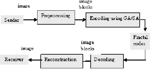
The architecture of the proposed method in iteration-free fractal coding is described in Fig.1 the encoder for GA and SA in Fig.2 and Fig.3and the decoder in fig.4 the sender sends the image for compression. In the preprocessing stage, the input MxN image under coding is divided into non overlapping square blocks of BxB pixels called the range blocks. The encoding takes place in the flowing steps.
The encoding procedure can be summarized in the following steps.
Step1: The mean μR and variance VR of each range block R(i,j) is determined. A mean image of size M/B x N/B with each pixel corresponding to the block mean is generated. The mean image must be larger than the size of the range block i.e. M/B x N/B > BxB.
Step2: The mean image is divided into blocks of the same size as the range block (B x B pixels) to form the domain pool.
Step3: If the variance of the range block is smaller than the threshold value E, then the range block (smooth block) is
coded by the mean, otherwise, the range block (rough block) will be coded by the fractal code f (i, α, µR, PD) using SA/GA technique. Here i represent the isometry
transformations, α the contrast scaling, µR the mean value of the range block and PD the domain block number in the domain pool.
= µR if VR ≤ E
=f (i, α, µR, PD) if VR > E (5)
A. Algorithm of the Encoder for the Proposed Iteration-free Fractal Image coding using GA
The algorithm of the proposed iteration-free fractal image coding using GA is given as follows:
Step1: Generate Knuth random numbers globally
Step2: Partition the given image into range blocks X of size B x B and find the mean and variance of each X.
Step3: Plot the mean image using the mean of X as the pixel value and partition this mean image into blocks of size B x B to form the domain pool. Decide on the length of the chromosomes, crossover probability, mutation probability, population size and number of iterations.
For each range block X:
Step4: If variance(X) < E assign 0 to label and µx to code. Else assign 1 to label. Generate the initial population. Calculate the RMS value of X and each population. Store the values. Compute the next iteration using the roulette wheel selection procedure and apply crossover and mutation probability. Calculate the RMS value of X and each population for each iteration. Use elitism to restore the previous best solution. Return the Fractal code of the minimum RMS values after the last iteration.
B. Algorithm of the Encoder for the Proposed Iteration-free Fractal Image coding using SA
The algorithm of the proposed iteration-free fractal image coding using SA is given as follows:
Step5: Start by generating an initial solution s (randomly) and by initializing the control parameter T.
Step6: Then the following is repeated until the termination condition is satisfied:
Step7: A solution s' is randomly sampled and it is accepted as new current solution depending on f(s), f(s') and T. Step8: s' replaces s if f(s') < f(s) or, in case f(s') >= f(s),
with a probability following the Boltzmann distribution exp(-(f(s') - f(s))/T).
C. Algorithm of the Decoder GA
The decoding process is as follows:
Step1: Extract the mean information of each range block from the fractal codes and construct the mean image. Step2: The domain pool is obtained by partitioning the
mean image using the same size as the range block for GA.
Step3: For smooth blocks, the decompressed image blocks are obtained by the mean value and for rough blocks apply contractive affine transformation using the fractal codes.
D. Algorithm of the Decoder SA
The decoding process is as follows:
Step4: Extract the mean information of each range block from the fractal codes and construct the mean image. Step5: The domain pool is obtained by partitioning the mean image using the same size as the range block for SA. Step6: For smooth blocks, the decompressed image blocks
are obtained by the mean value and for rough blocks apply contractive affine transformation using the fractal codes.
The outputs of the decoder are image blocks that are combined to form the decoded image at the receiver end. Thus the receiver gets the fractal codes as input and the decompressed image as output
.
)
,
(
i
j
III. ALGORITHM FOR ENCODING AND DECODING In the proposed method a synthetic codebook is created as the domain pool using the mean image, whose pixel values are the block means of all the range blocks. This code book is used as the domain pool for SA/GA technique.
A. Encoder Using GA
In the proposed method a synthetic codebook is created as the domain pool using the mean image, whose pixel values are the block means of all the range blocks. This code book is used as the domain pool for genetic algorithm technique. The architecture of the proposed method is described in Fig 1.
Fig.1 Architecture of the Proposed Iteration-Free Fractal Image Coding Method
The sender sends the color image for compression. In the preprocessing stage, the input MxN image under coding is divided into non-overlapping square blocks of BxB pixels called the range blocks. Then the mean and variance of each range blocks are determined. For each range block the red, green and blue component’s mean and variance are computed and then concatenated. After the mean of all the range blocks are obtained, a mean image of size M/B x N/B with each pixel corresponding to the block mean is generated.
The mean image must be larger than the size of the range block i.e. M/B x N/B > B x B. The maximum size of B is limited to 8 in order to produce a good quality of the decoded image. The higher the resolution of the input image (MxN) more blocks can be generated for the domain pool which helps to find a good mapping between the domain and range blocks. The initial domain pool with blocks of the same size as the range is generated using the mean image. In the encoder if the variance
2
,
0 ,
2 ( )
1 }
{ R
B j i
j i
r B
R
V
(2)
of the range block is smaller than the threshold value E, the
range block is coded by the mean, or else the range block will be coded by the contractive affine transformation [4, 9]. The aim of the proposed scheme is to find the domain block for each image range block and the transformation parameters that minimize the distortion between the image block and the transformed domain block in a minimized time. This process of finding the best domain block makes use of the techniques GA.
The random numbers required for GA is globally generated using Knuth algorithm for random numbers. The sizes of
the chromosomes and population, the number of generations and the probability for crossover and mutation are finalized only by trial that results in good compression ratio and PSNR. Then GA method is applied to search the best domain block with the required transformation that matches the range block. The architecture of the encoder using GA method is described in Fig.2.
Fig. 2 Proposed Encoder Using GA
The number of possible domain blocks to be searched is (M/B2) x (N/B2), the number of isometry transformations to be searched for each domain block is eight and the contrast scaling parameter is four for each RGB color components. Thus, the space to be searched consists of N1 elements for each RGB color components. N1 = 8 x 4 x (M/B2) x (N/B2). Let the space to be searched for each RGB color components be represented by P where
(3)
Binary strings are introduced to represent the elements of P [5] [10]. The set of 2n binary strings, each of length n for each RGB color components, are constructed in such a way that the set exhausts the whole parametric space. The value for n depends on the values of M, N and B. The fitness value of a string between the given range block and the obtained range block is taken to be the MSE given in Equ. 4. Let S be the population size and T be the maximum number of iterations for the GA. Note that the total number of strings searched up to T iterations is S x T. Hence, N1/SxT
provides the search space reduction ratio for each rough type range block.
2
, , 0
, , 2
1
)
,
(
B j i
j i j
i
r
r
B
R
R
MSE
(4)B. Encoder using SA
parameter is gradually reduced as the simulation proceeds. Initially, T is set to a high value (or infinity), and it is decreased at each step according to some annealing schedule — which may be specified by the user, but must end with T=0 towards the end of the allotted time budget. Cooling schedule Ti = T0 –i (T0 – TN) / N is used in the proposed method. Ti is the temperature for cycle i, where i
increases from 0 to N. The initial and final temperatures, T0 and TN respectively, are determined by the user, as is N. In the proposed method the value of N is chosen to be 40. The probability of making the transition to the new state s' is a function P(δE, T) of the energy difference δE = E(s') - E(s) between the two states, and of a global time-varying parameter T called the control parameter.In the proposed method T is made to vary from 1 to 0. The architecture of the encoder using GA method is described in Fig.3.
Fig. 3 Proposed Encoder Using SA
C. Decoder Using GA/SA
In the decoder, shown in Fig. 4 the mean information of each range block is extracted from the fractal codes. Using this information the mean image is constructed. This mean image is partitioned into blocks of the same size as the input image. This forms the domain pool for GA/SA search methods. The decompressed image is constructed block by block by applying the transformation parameters to the selected domain block from the domain pool as per the code.
Fig 4. Proposed Decoder
IV. IMPLEMENTATION OF SA/GA
These algorithms were implemented using the software Matlab 7.12 Parallel processing and Image processing tool on the Intel (R) Core[TM]2 E7500 system with 2.93 GHz and 1.96 GB of RAM. For implementation of these algorithms, four 512 x 512 benchmark color images of Lena, Pepper, Cauliflower and Tajmahal [shown in Figure 5 (a) to (d)] with twenty four-bit RGB color resolution were used. In the simulation, the images were partitioned into range blocks with the single size, either 8x8 or 4x4 or 2x2. The maximum block size is set to 8x8 because for a range block size greater than 8x8 the determination of the proper domain block was difficult and the quality of the image reconstructed was poor.
(a) Lena (b) Pepper
(c) Cauliflower (d)Taj Mahal Fig 5. Original (512 X 512, 24 Bit/Pixel) Images.
The threshold value for the variance of range blocks was chosen by trial and error basis to be of size 20 for block size 8x8, 10 for 4x4 and 5 for 2x2 that results in good compression ratio and PSNR. The number of blocks in the mean image is the size of the domain pool.
The range block with a single size (8x8, 4x4 & 2x2) was considered for simulation. Here the total number of range blocks for the block size 4x4 for each RGB color component was n = 16384 and total number of domain blocks (m) to search for each RGB color component were (128 / 4) x (128 / 4) = 32 x 32. Thus, the cardinality (N1) of the search spaces for each RGB color component of this case was 8 x 4 x 1024.The string length n for each RGB color component was taken to be 15 (3 + 2 + 10). Hence, the search space reduction ratio was approximately 14.
(a) 64x64 (b)128x128 (c)256x256
Fig 6. Mean Image of Lena for block size 8x8, 4x4 and 2x2
V. RESULTS AND DISCUSSIONS
The range blocks were classified before coding. Range blocks were grouped into two sets according to the variability of the pixel values in these blocks. If the variability of a block was low, i.e., if the variance of the pixel values in the block was below a fixed value, called the threshold, the block is called smooth type range block. Otherwise, it is called a rough type range block. The purpose of choosing this block classification was for two reasons. One is to get higher compression ratio, and the other is to reduce the coding time. The threshold value that separates the range blocks into two types was chosen as stated earlier. After classification, GA/SA-based coding was adopted for the rough type range blocks only. All the pixel values in a smooth type range block were replaced by the mean of its pixel values. This scheme is a time-saving one provided; the number of smooth type range blocks is significant. The storage requirements for the proposed method can be calculated from the number of smooth and rough blocks multiplied by the number of bits required to store the values. Table I ,II gives the classification of blocks, coding time, bit rate and compression ratio.
a) 2x2 b) 4x4
c) 8x8 Fig7. Decoded Images of Lena
Fig 7 (a), (b) and (c) shows the decompressed Lena image using the proposed method for a single level partition of size 8x8, 4x4 and 2x2.
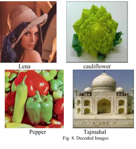
The RMS of the decoded image partitioned by the 8x8 block size is higher than that partitioned by the 4x4 and 2x2 block size since a smaller block size leads to a smaller matching error for the affine transformation. However, the bit rate increases significantly because the number of the 2x2 range blocks is four times the number of the 4x4 range blocks and number of the 4x4 range blocks is four times the number of the 8x8 range blocks. The decompressed image of Pepper, Cauliflower and Taj Mahal for the single block partition of sizes 8x8, 4x4 and 2x2 using SA are shown in Fig.8.
Lena cauliflower
Pepper Tajmahal Fig 8. Decoded Images
Table I
Classification of Blocks Compression Ratio, encoding time And Bit Rate on the Chosen Images Using SA
Table II
Classification of Blocks Compression Ratio, encoding time And Bit Rate on the Chosen Images Using GA Image Range Bit
Rate Comp ression Ratio
No of Range Blocks
Encod -ing Time Serial
Encod -ing Time Parallel Smooth Rough
Lena
2 * 2 7.56 3.17 43927 21611 110330 18090
4 * 4 1.95 12.26 8394 7992 63871 6699.1
8 * 8 0.48 49.82 1559 2539 31250 2860.6
Pepper
2 * 2 7.02 3.41 51409 14129 77985 12114
4 * 4 1.87 12.81 9851 6535 52157 6811.5
8 * 8 0.47 50.16 1638 2460 36276 2178.9
Cauli flower
2 * 2 7.16 3.34 49433 16105 84643 13773
4 * 4 1.94 12.34 8640 7746 50683 6728.9
8 * 8 0.47 50.36 1682 2416 34054 2127.3
Taj mahal
2 * 2 7.51 3.19 44672 20866 110470 17657
4 * 4 2.05 11.65 6624 9762 64737 13168
8 * 8 0.50 47.73 1018 3080 31250 2627.5
Image Rang e
Bit Rate
Comp ression Ratio
No of Range Blocks
Encod -ing Time Serial
Encodi ng Time Parallel Smooth Rough
Lena
2 * 2 7.56 3.17 43927 21611 123750 25568
4 * 4 1.95 12.26 8394 7992 17739 14097
8 * 8 0.48 49.82 1559 2539 17784 7325
Pepper
2 * 2 7.02 3.41 51409 14129 11363 25049
4 * 4 1.87 12.81 9851 6535 14248 14016
8 * 8 0.47 50.16 1638 2460 17076 8250.6
Cauli flower
2 * 2 7.16 3.34 49433 16105 17989 59437
4 * 4 1.94 12.34 8640 7746 13016 47741
8 * 8 0.47 50.36 1682 2416 20484 11225
Taj mahal
2 * 2 7.51 3.19 44672 20866 16526 53736
4 * 4 2.05 11.65 6624 9762 25991 23147
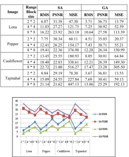
Table III gives the RMS and PSNR using different types of encoding using the proposed technique on the color images chosen for simulation. From the results tabulated in Table 1, it is observed that for the images which have the number of smooth blocks significantly high has a high compression ratio.
Table III
Classification of Blocks RMS and PSNR value On the Chosen Images Using SA
Fig.9 Comparison performance of GA and SA RMS and PSNR
VI.CONCLUSIONS
In this paper, our coding scheme to apply an improved a fast-encoding algorithm for fractal image coding is proposed and implemented using SA/GA for still color image. The proposed algorithm has the better performance in terms of image quality, bit rate and coding time for RGB image. Only the encoding consumes more time but the decoding is very fast. Applications where images can be stored in a compressed form, which require faster retrieval, like medical images and photographs for identification can use the proposed method. The execution time can be further reduced by implementing the proposed method in parallel for encoding Data compression is used primarily in transmission and storage of information. Image transmission applications are in broadcast television, remote sensing via satellite, military communication via aircraft, radar and sonar, teleconferencing, computer communication, facsimile transmission and the like. Image storage is required for educational and business documents, medical images, digital radiology, motion pictures, satellite images, weather maps, geological surveys, and so on.
ACKNOWLEDGMENT
The work has been supported by the UGC.
REFERENCES
[1] B. Schouten, and P. de Zeeuw, “Feature extraction using fractal codes,” in Visual 99; visual information and information systems, Third International Conference, Springer, Berlin, pp. 483- 492, 1999.
[2] J. Puate, and F. Jordan, “Using fractal compression scheme to embed a digital signature into a image,” Proc. SPIE, Vol.2915, pp. 108- 118, 1997.
[3] M. Ancis, W. Buchwald, P. Giusto, D. Daniele, and D.
Schmidt, “Fractal zooming of thumbnails for progressive image coding,” in C.-C.J. Kuo, S.-F. Chang, S. Panchanathan (Eds.), Multimedia Storage and Archiving Systems III, Proceesings of the SPIE, Rhode Island, USA, Vol.3527, pp. 541-549, 1998.
[4] H.A. Cohen, “Thumbnail-based image coding utilizing the fractal transform,” Proceedings of the ICIP-96 IEEE International Conference on Image Processing, Lausanne, September 1996.
[5] L.M. Kaplan, and C.C. Jay Kuo, “Texture segmentation via haar fractal feature estimation,” J. Visual Commun. Image Representation, 6 (4), pp. 387-400, 1995.
[6] Barnsley M. F. Fractals Everywhere. New York: Academic, 1988.
[7] Michael F. Barnsley, A Better Way to Compress Images,
BYTE, 215-222, Jan. 1988
[8] Y.Fisher, E.W.Jacbos, and R.D.Boss, “Fractal image
compression using iterated transforms,”image and text Compression , j.A.storer,Ed.Boston,36-61,1992.
[9] Y.Fisher,”Fractal Image Compression-Theory and
Application”,Springer-verlag,1994.
[10] Hamzaoui R. Decoding algorithm for fractal image
compression. Electron. Lett., 32, 1273-1274, July 1996.
[11] Jacquin A. E. Fractal image coding: A review. Proc. IEEE,
81, 1451–1465, Oct. 1993
[12] Jacquin A. E. Image Coding Based On A Fractal Theory Of Iterated Contractive Image Transformations. IEEE Trans. Image Processing, 1, 18–30, Jan. 1992.
[13] Mohsen Ghazel, George H.Freeman and Edward R.Vrscay.
Fractal Image Denoising, IEEE Trans. Image Processing,
12(12), 1560–1578, Dec. 2003.
[14] Wohlberg B. and G. de Jager. A Review Of The Fractal
Image Coding Literature, lEEE Trans Image Processing, 8, 1716-1729, Dec 1999.
[15] Erjun Zhao Dan Liu. Fractal image compression methods: a review. Proceedings of the Third International Conference on Information Technology and Applications (ICITA’05), pp 756-759, 2005.
[16] N.A .Koli and M.S. Ali,” A survey on fractal image
compression key issues”, Information technology Journal 7(8): pp 1085-1095, 2008.
[17] Alexander S. K., P. Fieguthand and E. R. Vrscay. Image
Sampling By Hierarchical Annealing.
0-7803-7750-8/03/$17.00 © 2003 IEEE, I-249 – I-252, 2003
[18] Tie Wang,Jeffry W.Touchma,Guoliang xue," Applying
Two-level Simulated Annealing on Bayesian Structure Learning to Infer Genetic Network, proceeding IEEE computational Systems bioinformatics conference,2004. Image
Range Block size
SA GA
RMS PSNR MSE RMS PSNR MSE
Lena
2 * 2 6.87 31.38 47.30 3.71 36.73 13.79
4 * 4 11.03 27.27 121.73 7.25 30.92 52.59
8 * 8 16.22 23.92 263.18 10.64 27.58 113.39
Pepper
2 * 2 7.75 30.34 60.11 4.51 35.03 20.37
4 * 4 12.41 26.25 154.17 7.43 30.71 55.21
8 * 8 19.41 22.36 376.98 12.28 26.34 150.99
Cauliflower
2 * 2 13.45 25.55 180.93 8.05 30.01 64.84
4 * 4 18.40 22.83 338.61 12.21 26.39 149.30
8 * 8 22.72 21.00 516.27 17.47 23.28 305.50
Tajmahal
2 * 2 8.84 29.19 78.30 3.67 36.81 13.53
4 * 4 15.09 24.55 227.84 7.69 30.41 59.13