TIMING SHIFT OF OPTICAL PULSES DUE TO INTER-CHANNEL CROSS-TALK
B. Stojanovic and D. M. Milovic
Faculty of Electronic Engineering Department of Telecommunications University of Nis
Aleksandra Medvedeva 14, 1800 Nis, Serbia
A. Biswas
Center for Research and Education in Optical Sciences and Applications
Department of Applied Mathematics and Theoretical Physics Delaware State University
Dover, DE 19901-2277, USA
Abstract—This paper considers the influence of interchannel crosstalk on pulse timing shift and optical power due to the propagation of optical pulse through a nonlinear dispersive fiber. The numerical results are shown. An influencing parameter of the pulse distortion through the fiber is the eye opening penalty.
1. INTRODUCTION
different frequency that interact with the useful signal. Another reason for crosstalk is induced by leakage or insufficient insulation.
In this paper, the influence of interchannel crosstalk timing shift and optical power on the propagation of the optical solitons through a single mode nonlinear dispersive optical fiber is considered. Both the crosstalk and the useful signal are Gaussian shape but with different wavelengths. The pulse distortion through the fiber for different crosstalk optical powers and crosstalk timing shifts.
2. DETERMINATION OF USEFUL SIGNAL INFLUENCED BY CROSS-TALK SIGNAL
The propagation of short optical pulses in nonlinear dispersive medium is considered. The cross-talk pulses being at different wavelengths than useful signal, so called interchannel cross-talk distort the useful pulses. It is assumed that the cross-talk occur at the transmitter output (fiber input). The useful signal is modeled as
s1(z, T) =A1(0, T) cos (ω1T) (1)
while the interchannel cross-talk signals is considered to be given by
s2(z, T) =A2(0, T) cos (ω2T) (2)
whereω1is the central frequency of a desired channel andω2represents
the central frequency of interchannel cross-talk.
In this paper, the input optical pulse envelope is assumed to be unchirped whose shape is given by
A1(0, T) =
P1f
− T2
2T02
(3)
The envelope of the interchannel cross-talk pulse is assumed to be given by
A2(0, T) =
P2f
−(T−Ts)2 2T02
(4)
where P1 and P2 are the peak powers of useful optical pulse and
The useful optical pulse and the above modeled interchannel cross-talk will co-propagate simultaneously through the optical fiber. This propagation is governed by the set of two coupled nonlinear Schr¨odinger’s equation which, in the dimensionless form, is given by
∂A1
∂z +
i
2β21
∂2A1
∂T2 = iγ1
|A1|2+ 2|A2|2
A1 (5)
∂A2
∂z +
i
2β22
∂2A2
∂T2 = iγ2
|A2|2+ 2|A1|2
A2 (6)
where γj = n2ωj/cAeff and β2j = −Dλ2j/2πc for j = 1,2 are the coefficients of dispersion and nonlinear terms respectively and
T = t−z/vg is the normalization factor. Also Aeff = πw2 is the effective core area. It needs to be noted thatAeff is typically 10−20µm2 in the visible region but it can be in the range of 50–80µm2 in the 1.55µm region, so that γ can vary over the range 2–30 W−1km−1 depending on n2 and frequency. Also it is assumed that the fiber
losses are small and therefore neglected.
The coupled equations in (5) and (6) is a nonlinear partial differential equation. This system is solved by using the split-step Fourier method that is extensively used in solving pulse propagation problem in a nonlinear dispersive medium. In a lot of cases this method shows high accuracy. Although, in general, the dispersion and nonlinearity act together along the fiber, the split-step Fourier method gives an approximate solution by assuming that in the propagation of optical field over a small distance h one can pretend that dispersive and nonlinear effects act independently. Hence, propagation fromz to
z+h is carried out in two steps. In the first step, nonlinearity acts alone while in the second step dispersion acts alone. Thus the name split-step method. Although the method is relatively straightforward to implement, it should be noted that it requires the step sizehalongz
and time discretization to be selected carefully to maintain the required accuracy.
The interchannel cross-talk level is defined by signal-to-interference ratio (SIR) i.e., the ratio of useful signal optical power to cross-talk to cross-talk signal optical power. It is defined as
SIR = 20 logP1
P2
(7)
3. NUMERICAL SIMULATION OF PULSE EVOLUTION
In the propagation of optical pulses, the following factors are taken into considerationTFWHM = 12.5 ps, λ1 = 1550 nm, bit rateR = 20 Gb/s,
P −1 = 50 mW through the SMF in the regime of normal dispersion (D= 0.2 ps/nm-km) with parameterAeff = 50µm2. The interchannel cross-talk wavelength is taken to be λ2 = 1551.5 nm. The fiber length
is taken to be 60 km in all the simulations.
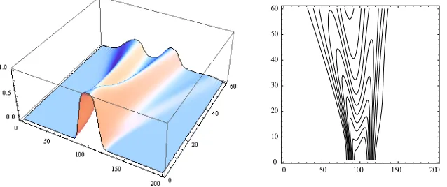
The contour plot is used as a very illustrative way to show variations of power and distortion of pulse during propagation through the nonlinear dispersive SMF. In the worst case SIR = 0 dB, i.e., the useful signal has an equal magnitude to cross-talk signal, is considered.
0 50 100 150 200
0 10 20 30 40 50 60
Figure 1. Pulse evolution picture and corresponding contour plot (Gaussian pulse).
0 50 100 150 200
0 10 20 30 40 50 60
0 50 100 150 200 0
10 20 30 40 50 60
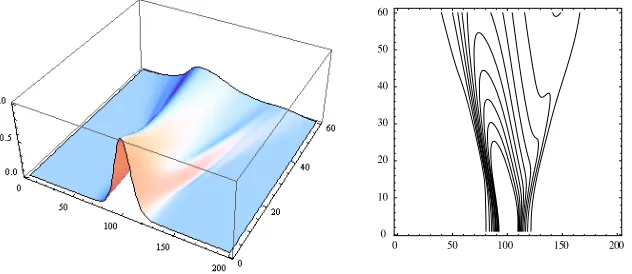
Figure 3. Pulse evolution picture and corresponding contour plot (sech pulse).
0 50 100 150 200
0 10 20 30 40 50 60
Figure 4. Pulse evolution picture and corresponding contour plot (super-sech pulse).
These figures are respectively due to Gaussian, super-Gaussian, sech and super-sech pulses.
4. EYE OPENING PENALTY
deterministic pulse distortion effects. EOP is defined as a ratio of an initial eye opening (EObefore) to the eye opening after transmission (EOafter). The initial eye opening is the eye opening that is measured at the fiber input.
The analysis of the influence of interchannel crosstalk occurring at the fiber input for a different useful signal optical powers and for the worst case when SIR = 0 dB by estimating the EOP and changing
Ts. The influence of interchannel cross-talk by estimating EOP and changing SIR is also analysed in Figures 5–8, for various types of pulses.
-0.4Tb -0.2Tb 0.0Tb 0.2Tb 0.4Tb 1 2 3 4 5 6 7 8 9 10 11 EOP Ts SIR=0 dB SIR=5 dB SIR=10 dB Pm=50mW
Figure 5. EOP vs Ts for Gaus-sian optical pulse and different SIR.
-0.4Tb -0.2Tb 0.0Tb 0.2Tb 0.4Tb
0 1 2 3 4 5 6 7 8 9 10 11 12 13 14 15 16 17 18 EOP Ts
SIR= 0 dB SIR=5 dB SIR=10 dB Pm=50mW
Figure 6. EOP vs Ts for super-Gaussian optical pulse and different SIR.
-0.4Tb -0.2Tb 0.0Tb 0.2Tb 0.4Tb
0 2 4 6 8 10 EOP Ts SIR=0 dB SIR=5 dB SIR=10 dB Pm=50mW
Figure 7. EOP vs Ts for sech optical pulse and different SIR.
-0.4Tb -0.2Tb 0.0Tb 0.2Tb 0.4Tb
2 3 4 5 6 7 8 9 10 11 12 13 EO P Ts SIR=0 dB SIR=5 dB SIR=10 dB Pm=50mW
It is be seen that interchannel cross-talk occurring at the fiber input greatly reduce eye opening by increasing the useful signal optical power. The 3-D plots of Figures 1–4 illustrate this. The very same conclusion can be drawn from Figures 5–8. The eye opening is rising with the increase of SIR and decreases with the increase of the useful signal optical power.
5. CONCLUSIONS
Although the interchannel cross-talk can be filtered if it occurs at the fiber input, it not uncommon that this cross-talk can be induced somewhere, rather anywhere, in the transmission link. In this paper, the investigation of the interchannel cross-talk was investigated that occurs at the fiber input. The analysis is performed for the interchannel cross-talk model where the interchannel cross-talk position relative to the useful signal position is considered and it was concluded that
Ts influences EOP. It can be seen that the interchannel cross-talk position at the center of the useful signal Ts = 0 has the greatest influence. As the position of the cross talk pulse is changed left or right (0 ≤ |Ts| ≤ Tb/2), the useful signal pulse becomes additionally distorted but the influence on the EOP becomes smaller as observed in Figures 5–8. The SIR level is also changed from 0–20 dB and numerically simulated EOP and it is seen that for SIR = 0 dB, one has the greatest influence on optical pulse propagation. This means that when interchannel cross-talk optical power is equal to the signal optical power, it gives rise to nonlinear effects that additionally distorts the pulse shape. A thorough analysis is very useful for improving the existing transmission links or designing the new ones. It is also very useful in designing wavelength-division-multiplexed (WDM) systems as this type of cross-talk is pretty common. So, in the case of WDM system two or even four nearest wavelengths (channels) should be taken into consideration. It needs to be noted that EOP gives an useful information for bit-error-rate evaluation.
ACKNOWLEDGMENT
REFERENCES
1. Biswas, A., “Dispersion-managed solitons in optical fibres,” Journal of Optics A, Vol. 4, No. 1, 84–97, 2002.
2. Biswas, A. and S. Konar, Introduction to Non-Kerr Law Optical Solitons, CRC Press, Boca Raton, FL, 2006.
3. Biswas, A., S. Konar, and E. Zerrad. “Soliton-soliton interaction with parabolic law nonlinearity,” Journal of Electromagnetic Waves and Applications. Vol. 20, No. 7, 927–939, 2006.
4. Biswas, A., Shwetanshumala, and S. Konar, “Dynamically stable dispersion-managed optical solitons with parabolic law nonlinear-ity,”Journal of Electromagnetic Waves and Applications, Vol. 20, No. 9, 1249–1258, 2006.
5. Biswas, A., “Stochastic perturbation of parabolic law optical solitons,” Journal of Electromagnetic Waves and Applications, Vol. 21, No. 11, 1479–1488, 2007.
6. Gangwar, R., S. P. Singh, and N. Singh, “Soliton based optical communication,” Progress In Electromagnetics Research, PIER 74, 157–166, 2007.
7. Hirooka, T. and S. Wabnitz, “Nonlinear gain control of dispersion-managed soliton amplitude and collisions,” Optical Fiber Technology, Vol. 6, No. 2, 109–121, 2000.
8. Jana, S. and S. Konar, “Tunable spectral switching in far field with a chirped cosh-Gaussian pulse,”Optics Communications, Vol. 267, No. 1, 24–31, 2006.
9. Jana, S. and S. Konar, “A new family of Thirring type optical spatial solitons via electromagnetic induced transparency,” Physics Letters A, Vol. 362, No. 5–6, 435–438, 2007.
10. Jovanoski, Z. and D. R. Rowland, “Variational analysis of solitary waves in a homogenous cubic-quintic nonlinear medium,”Journal of Modern Optics, Vol. 48, No. 7, 1179–1193, 2001.
11. Kohl, R., A. Biswas, D. Milovic, and E. Zerrad, “Optical soliton perturbation in a non-Kerr law media,” To appear in Optics and Laser Technology.
12. Konar, S. and A. Sengupta, “Propagation of an elliptic Gaussian laser beam in a medium with saturable nonlinearity,”Journal of Optical Society of America B, Vol. 11, No. 9, 1644–1646, 1994. 13. Konar, S., J. Kumar, and P. K. Sen, “Suppression of soliton
14. Konar, S. and S. Jana, “Linear and nonlinear propagation of sinh-Gaussian pulses in dispersive media possessing Kerr nonlinearity,” Optics Communications, Vol. 236, No. 1–3, 7–20, 2004.
15. Konar, S., M. Mishra, and S. Jana, “The effect of quintic nonlinearity on the propagation characteristics of dispersion-managed optical solitons,” Chaos, Solitons & Fractals, Vol. 29, No. 4, 823–828, 2006.
16. Konar, S., S. Jana, and S. Shwetanshumala, “Incoherently coupled screening photovoltaic spatial solitons in biased photovoltaic photorefractive crystals,”Optics Communications, Vol. 273, No. 2, 324–333, 2007.
17. Konar, S., M. Mishra, and S. Jana, “Nonlinear evolution of cosh-Gaussian laser beams and generations of flat-top spatial solitons in cubic-quintic nonlinear media,” Physics Letters A, Vol. 362, No. 5–6, 505–510, 2007.
18. Lim, M., S. C. Yeow, P. K. Choudhury, and D. Kumar, “Towards the dispersion characterestics of tapered core dielectric optical fibers,” Journal of Electromagnetic Waves and Applications, Vol. 20, No. 12, 1507–1609, 2006.
19. Mandal, B. and A. R. Chowdhury, “Spatial soliton scattering in a quasi-phase matched quadratic media in presence of cubic nonlinearity,” Journal of Electromagnetic Waves and Applications, Vol. 21, No. 1, 123–135, 2007.
20. Medhekar, S., S. Konar, and M. S. Sodha, “Self-tapering of elliptic Gaussian beams in elliptic core nonlinear fiber,” Optics Letters, Vol. 20, No. 21, 2192–2194, 1995.
21. Mishra, M. and S. Konar, “All optical light deflection and displacement using nonlinear slab waveguide,” Fiber and Integrated Optics, Vol. 23, No. 4, 275–285, 2004.
22. Mishra, M. and S. Konar, “Interaction of solitons in a dispersion-managed optical communication system with asymmetric disper-sion map,” Journal of Electromagnetic Waves and Applications, Vol. 21, No. 14, 2049–2058, 2007.
23. Panajotovic, A., D. Milovic, and A. Biswas, “Influence of even order dispersion on soliton transmission quality with coherent interference,” Progress In Electromagnetics Research B, Vol. 3, 63–72, 2008.
25. Shwetanshumala, S. Jana, and S. Konar, “Propagation of a mixture of modes of a laser beam in a medium with saturable nonlinearity,” Journal of Electromagnetic Waves and Applications, Vol. 20, No. 1, 65–77, 2006.
26. Shwetanshumala, A. Biswas, and S. Konar, “Dynamically stable super-Gaussian solitons in semiconductor doped glass fibers,”
Journal of Electromagnetic Waves and Applications, Vol. 20,
No. 1, 65–77, 2006.
27. Stefanovic, M. C. and D. M. Milovic, “The impact of out-of-band cross-talk on optical communication link performances,” To appear inJournal of Optical Communications.
28. Turitsyn, S. K., E. A. Shapiro, S. B. Medvedev, M. P. Fedoruk, and V. K. Mezentsev, “Physics and mathematics of dispersion-managed optical solitons,”Comptes Rendus Physique, Vol. 4, 145– 161, 2003.
29. Zhang, J. and T. Hsiang, “Dispersion characterestics of coplanar waveguides at subterahertz frequencies,” Journal of Electromagnetic Waves and Applications, Vol. 20, No. 10, 1411– 1417, 2006.