Available online:
https://edupediapublications.org/journals/index.php/IJR/
P a g e | 1743Coupled Inductor Based Five Phase Inverter
K.HA RI KRISHNA1,B.JA YA RA JU2
1
M-Tech,Department of EEE, ASRIT College of Engineering
2
Assistant Professor, Department of EEE, ASRIT College of Engineering
ABSTRACT :
Multi-level inverters are became popular for usage in medium voltage, low voltage power applications due to flexibility in control and better performance characteristics in terms of harmonic regulation. Neutral point clamped are popular as they require less number of sources as their input when compared with their counter parts i.e. cascaded multi-level inverters and found to be reliable when compared with flying capacitor based multi-level inverters. But when neutral clamped technologies are used for generation of three-phase voltages, the capacitors that are connected at input side experiences imbalance in their voltages, this makes neutral point clamped multi-level inverters less reliable. In the proposed work an attempt is made to study circuits that balance the capacitor voltages and a scheme is investigated for balancing the capacitor voltages. Method proposed in [2] uses PID controller for balancing the capacitor voltages. In this project PI based control scheme and artificial neural network (ANN) based control scheme for the front end circuit shown in [2] are designed for achieving balance among the capacitor voltages. The proposed control scheme is simulated with the help of Simpowersystems block set and neural network toolbox of MATLAB software for different load conditions. Results obtain ed from ANN based controller and PI controller are presented.
Key wo rd s : multilevel inverter; ANN, PID Controller.
INTRODUCTION:
Multilevel converters (MLC) have the later years been looked upon as a decent choice for medium- and high-voltage applications. It had been first given in [2]. Before the introduction of multilevel converters the standard answer has been to attach semiconductors asynchronous to resist the high voltages. This needs fast change to avoid unequal voltage sharing between the devices that may lead to a breakdown. MLC have the advantage of clamping the voltages that prevents the necessity of quick change. MLC even have a smoother output voltage than traditional two-level converters. Most multilevel inverters have an arrangement of switches and capacitor voltage sources. By a proper control of the switching devices, these can generate stepped output voltages with low harmonic distortions. Recently, multilevel inverters have drawn tremendous interest in the field of high-voltage and high-power applications because it has some advantages: it can realize high voltage and high power output through low-voltage switches without transformer and dynamic voltage balance circuits, with increased output level and reduced harmonics are decreasing Multilevel inverters are mainly classified as diode-clamped, capacitor-clamped and cascaded H-bridge inverters. Among the basic multilevel inverters the problem of voltage unbalance of dc link capacitors exists inherently in the diode-clamped inverter topology, which limits the further application of it, especially at the level above three. To balance the voltage of dc link series capacitors, three main approaches have been proposed. They are:
1) Using separate dc sources, [3], [4]
2) Adding some auxiliary balancing circuits [5], [6] and
3) Improving the control method by selecting redundant switching states [7], [8].
Available online:
https://edupediapublications.org/journals/index.php/IJR/
P a g e | 1744these power conversion systems present. Each phase of a multilevel converter can generate more than two different voltage levels. Thus, compared with the conventional two -level converter, the generated voltage shave more possible steps to approach the sinusoidal waveforms, reducing in this way the harmonic distortion[11]. Nevertheless, the increase of the number of voltage levels leads to a higher complexity of the converter structure. Moreover, additional dc-link capacitors are also required in some topologies such as the NPC. Concerning these capacitors, the balancing of their voltages according to an operating point is one of the mayor technical challenges of the multilevel converters.
MULTI-LEVEL INVERTERS:
A voltage level of three is considered to be the smallest number in multilevel converter topologies. Due to the bi-directional switches, the multilevel VSC can work in both rectifier and inverter modes. This is why most of the time it is referred to as a converter instead of an inverter in this dissertation. A multilevel converter c an switch either its input or output nodes (or both) between multiple (more than two) levels of voltage or current. As the number of levels reaches infinity, the output THD approaches zero. The number of the achievable voltage levels, however, is limited by voltage-imbalance problems, voltage clamping requirements, circuit layout and packaging constraints complexity of the controller, and, of course, capital and maintenance costs. Three different major multilevel converter structures have been applied in industrial applications: cascaded H-bridges converter with separate dc sources, diode clamped, and flying capacitors.
DIODE-CLAMPED MULTILEVEL INVERTER:
The most commonly used multilevel topology is the diode clamped inverter, in which the diode is used as the clamping device to clamp the dc bus voltage so as to achieve steps in the output voltage. The neutral point converter proposed by Nabae, Takahashi, and Akagi in 1981 was essentially a three-level diode-clamped inverter. A three-level diode clamped inverter consists of two pairs of switches and two diodes. Each switch pairs works in complimentary mode and the diodes used to provide access to mid -point voltage. In a three-level inverter each of the three phases of the inverter shares a common dc bus, which has been subdivided by two capacitors into three levels. The DC bus voltage is split into three voltage levels by using two series connections of DC capacitors, C1 and C2. The voltage stress across each switching device is limited to Vdc through the clamp ing diodes Dc1 and
OPERATION OF DCMLI:
three-level diode-clamped converter in which the dc bus consists of two capacitors, C1, C2. For dc-bus voltage Vdc, the voltage across each capacitor is Vdc/2 and each device voltage stress will be limited to one capacitor voltage level Vdc/2 through clamping diodes. To explain how the staircase voltage is synthesized, the neutral point n is considered as the output phase voltage reference point. There are three switch combinations to synthesize three-level voltages across a and n.
1. Voltage level Van= Vdc/2, turn on the switches S1andS2.
2. Voltage level Van= 0, turn on the switches S2 and S1′.
3. Voltage level Van= - Vdc/2 turn on the switches S1′, S2′.
4. Figure. 2.2(b) shows a five-level diode-clamped converter in which the dc bus consists of four capacitors, C1, C2, C3, and C4. For dc-bus voltage Vdc, the voltage across each capacitor is Vdc/4 and
Available online:
https://edupediapublications.org/journals/index.php/IJR/
P a g e | 1745FEATURES OF DIODE CLAMPED MLI:
Hig h -Vo ltag e Ratin g Req u ired fo r Blo ckin g Dio d es :
Although each active switching device is only required to block a voltage level of Vdc/ (m - l), the clamping diodes need to have different voltage ratings for reverse voltage blocking. Using D1′ of figure. 2.2(b) (5-level diode clamped inverter) as an example, when all lower devices, S1′-S4′ are turned on, D1′ needs to block three capacitor voltages, or 4Vdc/4. Similarly, D2 and D2′ need to block 2Vdc/4, and D4 needs to block 4Vdc/4.
Un eq u al Dev ice Ratin g :
It can be seen that switch S1 conducts only during Vao= Vdc, while switch S4 conducts over the entire cycle except during Vao= 0. Such an unequal conduction duty requires different current ratings for switching devices. When the inverter design is to use the average duty for all devices, the outer switches may be oversized, and the inner switches may be undersized. If the design is to suit the worst case, then each phase will have 2 x (m - 2) outer devices oversized. In comparison with the traditional transformer coupling multi pulse converters using six-step operation for each converter, such unequal conduction duty is indeed an advantageous feature because the six-step operation needs maximum duty in each device and circulating currents between converters through transformers.
Cap acitor Vo ltage Unbalance:
In most applications, a power converter needs to transfer real power from ac to dc (rectifier operation) or dc to ac (inverter operation). When operating at unity power factor, the charging time for rectifier operation (or discharging time for inverter operation) for each capacitor is different. Such a capacitor charging profile repeats every half cycle, and the result is unbalanced capacitor voltages between different levels. The voltage unbalance problem in a multilevel converter can be solved by several approaches, such as replacing capacitors by a controlled constant dc voltage source such as pulse-width modulation (PWM) voltage regulators or batteries.
RESULTS:
For balancing the capacitor voltages of the TLBC we are using PI controller. To get the better performance we are replacing the PI controller with ANN scheme
.
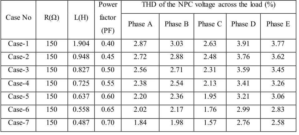
Table : Case studies of the ANN controlled NPC multilevel inverter.
Case No
R(Ω)
L(H)
Power
factor
(PF)
THD of the NPC voltage across the load (%)
Phase A
Phase B Phase C Phase D
Phase E
Case-1
150
1.904
0.40
2.87
3.03
2.63
3.91
3.77
Case-2
150
0.948
0.45
2.72
2.88
2.48
3.76
3.62
Case-3
150
0.827
0.50
2.56
2.71
2.31
3.59
3.45
Case-4
150
0.725
0.55
2.38
2.54
2.13
3.41
3.26
Case-5
150
0.637
0.60
2.20
2.36
1.95
3.21
3.06
Case-6
150
0.558
0.65
2.02
2.17
1.76
2.99
2.83
Available online:
https://edupediapublications.org/journals/index.php/IJR/
P a g e | 1746Case-8
150
0.421
0.75
1.66
1.80
1.38
2.51
2.31
Case-9
150
0.358
0.80
1.47
1.61
1.19
2.24
2.03
Case-10
15
0.296
0.85
1.27
1.44
1.01
2.00
1.79
Case-11
150
0.231
0.90
1.20
1.31
0.88
1.82
1.55
Case-12
150
0.157
0.95
1.05
1.16
0.72
1.52
1.20
Case-13
150
0.000
1.00
0.75
0.94
0.55
0.70
0.91
By observing the ANN controller, we can clearly see that NPC multilevel output is much better and quick settling time of capacitor voltages when compared to PI controller based NPC multilevel inverter. The case studies are done on ANN based NPC multilevel inverter for different load factors and the observations are tabulated
.
Case No
R(Ω)
L(H)
Power
factor
(PF)
THD of the NPC Current through the load (%)
Phase A
Phase B Phase C Phase D
Phase E
Case-1
150
1.904
0.40
3.91
3.77
3.99
3.77
3.91
Case-2
150
0.948
0.45
3.76
3.62
3.85
3.62
3.76
Case-3
150
0.827
0.50
3.59
3.45
3.69
3.45
3.59
Case-4
150
0.725
0.55
3.41
3.26
3.51
3.26
3.41
Case-5
150
0.637
0.60
3.21
3.06
3.32
3.06
3.21
Case-6
150
0.558
0.65
2.99
2.83
3.11
2.83
2.99
Case-7
150
0.487
0.70
2.76
2.58
2.89
2.58
2.76
Case-8
150
0.421
0.75
2.51
2.31
2.65
2.31
2.31
Case-9
150
0.358
0.80
2.24
2.03
2.40
2.03
2.24
Case-10
15
0.296
0.85
2.00
1.79
2.19
1.79
2.00
Case-11
150
0.231
0.90
1.82
1.55
2.02
1.55
1.82
Case-12
150
0.157
0.95
1.52
1.20
1.76
1.20
1.52
Available online:
https://edupediapublications.org/journals/index.php/IJR/
P a g e | 1747The above table shows the power factor values for various load inductances and THD in the output voltages and currents. For all cases, capacitor voltages of the TLBC, output voltages and currents are recorded.
The results are the voltage across the load and current through the load connected to the NPC
multilevel using PI controller.
Available online:
https://edupediapublications.org/journals/index.php/IJR/
P a g e | 1748Figure: Output wave forms of capacitor voltages C3 balanced by PI controller.
Available online:
https://edupediapublications.org/journals/index.php/IJR/
P a g e | 1749The results shown in figure.5.8 and 5.9 are the voltage across the load and current
through the load connected to the NPC multilevel using ANN controller.
Figure: Voltage across the NPC multilevel inverter using ANN controller.
Available online:
https://edupediapublications.org/journals/index.php/IJR/
P a g e | 1750Figure: Output wave forms of capacitor voltages C1 balanced by ANN
CONCLUSION:
roportional plus Integral based Control scheme and ANN based control scheme for capacitor voltage balancing for a five phase inverter are modelled and analysed with the help of simulation studies. The circuits thus modelled are applied to TLBC based five-level five phase neutral point clamped inverter.
Simulation studies are conducted using MATLAB SIMULINK software.
The performance of the control schemes are compared when the converter is supplying both balanced and unbalanced loads.
It has been observed that ANN based gives a better transient as well as study state response when compared with PI controller and achieves.
The time taken by the response to attain its study state value using PI controller is equal to 0.1 sec and using ANN controller is equal to 0.03 sec.
All the capacitors are subjected to equal voltage stress for equal time intervals in a given cycle of output voltage.
ANN based control scheme enhances life of the capacitors used in NPC multi-level inverter circuits. It has been observed that ANN based controller gives better transient response and quick settling time for the given input.
So, using ANN controller for balancing of voltages across capacitor of a n eutral point clamped multi-level inverter is a better option than a conventional PI controller.
BIBLIOGRAPHY:
[1]. Rosmadi Abdullah, Member, Nasrudin Abd. Rahim, Siti Rohani Sheikh Raihan and Abu Zaharin Ahmad : “Five-Level Diode-Clamped Inverter With Three-Level Boost Converter” IEEE Transactions on Industrial Electronics, Vol. 61, No. 10, October 2014
Available online:
https://edupediapublications.org/journals/index.php/IJR/
P a g e | 1751[3]. IlhamiColak, RamazanBayindir and ErsanKabalci, "Design and analysis of a 7-level cascaded
multilevel inverter with dual SDCSs," International Symposium on Power Electronics , Electrical Drives, Automation and Motion, volume 25, no.3, pp.4244-4987, october2010.
[4]. Fang ZhengPeng, Jih-Sheng Lai, John W. McKeever and James Van Coevering, "A multilevel voltage-source inverter with separate DC sources for static var generation," IEEE Transactions on Industry Applications, volume 32, no. 5, September/October 1996.
[5]. K. Sano and H. Fujita, "Voltage-balancing circuit based on a resonant switched-capacitor converter for multilevel inverters," IEEE Transactions on Industrial Application , volume 44, no. 6, pp. 17681776, November/December 2008.