A Novel Compact Dual-Wideband Bandpass Filter
with Multi-Mode Resonators
Jun Li1, 2, *, Shan-Shan Huang1, 3, Hui Wang4, and Jian-Zhong Zhao1
Abstract—A novel compact dual-wideband bandpass filter (BPF), with two multi-mode resonators (MMRs), a quad-mode one (QMR) and a triple-mode one (TMR), is proposed in this paper. The first passband is generated by a QMR loaded with a short-ended stub and two open-ended stubs, and the second one is realized by a TMR loaded with a square ring and a short-ended stub. Each passband can be tuned separately by controlling the corresponding resonator. The classical even-/odd-mode analysis is applied to characterize the presented MMRs due to their symmetric configurations. In order to validate the design methodology, a dual-wideband BPF prototype centered at 2.34 and 3.46 GHz with fractional bandwidths of 25.6% and 21.4% for WLAN and WiMAX applications is designed, fabricated and measured. Measurements have good agreement with simulations.
1. INTRODUCTION
In the last decades, dual-band bandpass filters (BPFs) have been aggressively investigated due to the rapid development of modern multi-band multi-service wireless communication systems. As a result, various dual-band BPFs have been reported [1–7]. For example, stepped-impedance resonators (SIRs) are employed to design a dual-band BPF in [1]. In [2] quarter-wavelength SIR is used to implement dual-band BPF. A tri-band BPF using asymmetric SIR with one step discontinuity is proposed in [3]. However, the center frequencies cannot be independently controlled. By utilizing two pairs of degenerate modes of a single ring resonator, dual-band response is achieved in [4]. However, this solution needs indispensable perturbations and suffers from notch-like upper stopband. Dual-band BPF, which resonant frequencies can be controlled by tuning the centrally loaded stubs, is realized by stub-loaded resonators in [5]. In [6], center-grounded SIRs are introduced to design dual-band filter. Multi-mode resonators (MMRs) are proposed to implement dual-band BPFs in [7]. Although these filters are qualified for some applications, the bandwidths of these filters are not wide enough to satisfy the requirement in modern dual high data-rate communication systems. Thus, dual-wideband BPFs are needed. Recently, some dual-wideband BPFs have been reported [8–11]. Short-circuited SIRs [8], transversal signal-interaction concept [9], open stub-loaded coupled-line section [10], and penta-mode resonator [11] are introduced to implement dual-wideband BPFs. However, only a few designs of high performance dual-wideband BPFs have been reported so far.
In this letter, a novel compact dual-wideband BPF with two MMRs is proposed. The first MMR is a quad-mode resonator (QMR) which consists of a main transmission line loaded with a short-ended stub and two open-ended stubs, and the second MMR is a triple-mode resonator (TMR) which is composed of a main transmission line loaded with a square ring and a short-ended stub. Even-/odd-mode analysis is applied to explain their resonant characteristics due to their symmetric configurations.
Received 23 December 2014, Accepted 22 January 2015, Scheduled 30 January 2015 * Corresponding author: Jun Li (lijun [email protected]).
By arranging the four and three resonant modes of the QMR and TMR within the desired passbands, and then connecting the two resonators with a common short-ended via-hole and feeding them with a pair of common feedlines, the proposed dual-wideband BPF is constituted. The center frequency (CF) and bandwidth of each passband can be tuned separately by controlling the corresponding resonator. Finally, the design method is verified by a fabricated prototype filter, and the measured results agree well with the simulated ones.
2. DUAL-WIDEBAND BPF DESIGN
2.1. Analysis of the Proposed MMRs
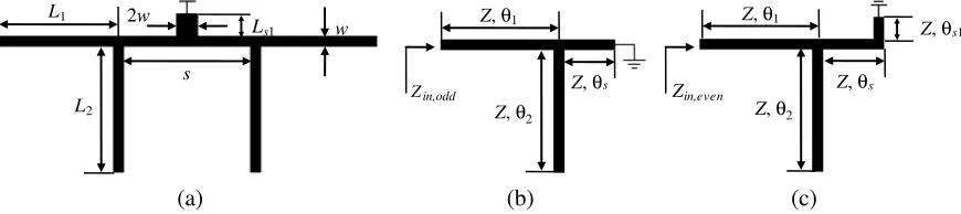
Figure 1(a) illustrates the specific configuration of the QMR which generates the first passband. As can be seen in Figure 1(a), it consists of a main transmission line loaded with a short-ended stub and two open-ended stubs. For analysis simplicity, the widths of the main transmission line and the loaded open-ended stubs are w, whereas the width of the loaded short-ended stub is 2w. In addition, the condition with θ1 =θ2 =θ=π/2 at frequency fm1 is considered in this section, where θn = 2πLn/λg
(n = 1,2, s, s1) and λg is the guided wavelength at fm1. Since the QMR is symmetric in structure,
even-/odd-mode analysis can be adopted to characterize it.
w
2w
L1
s
L2
Ls1
Z, θ
Zin,odd Zin,even
(a) (b) (c)
Z, θ
1
2
Z, θs
Z, θ1
Z, θ2
Z, θs
Z, θs1
Figure 1. (a) Configuration of the QMR, (b) odd- and (c) even-mode equivalent circuits of (a).
For the odd-mode excitation, the symmetrical plane is equivalent to an electric wall, and Figure 1(b) depicts its equivalent circuit. The one-port input impedance of the odd-mode equivalent circuit is
Zin, odd =jZ
tan2θ−cotθstanθ−1
2 tanθ−cotθs
(1)
The odd-mode resonance occurs whenZin, odd=∞, which is
tanθ = ∞ (2a)
2 tanθ−cotθs = 0 (2b)
By solving Equation (2), the odd-mode resonant frequencies of the QMR can be obtained as
fo1 = fm1 (3a)
fo2 =
2fm1 π tan−1
cot (sπ/λg)
2
(3b)
For the even-mode excitation, the symmetrical plane can be modeled as a magnetic wall, and its equivalent circuit is illustrated in Figure 1(c). The input impedance of the even-mode equivalent circuit is
Zin, even=jZ
tan2θ−cot (θs+θs1) tanθ−1
2 tanθ−cot (θs+θs1)
(4)
By applying the even-mode resonant condition Zin, even=∞, the following equations can be obtained
tanθ = ∞ (5a)
Thus, the even-mode resonant frequencies of the QMR can be expressed as
fe1 = fm1 (6a)
fe2 =
2fm1 π tan−1
cot ((s+ 2Ls1)π/λg)
2
(6b)
From Equations (3) and (6), one can clearly observe that the QMR generates four resonant modes (i.e., fo1, fo2,fe1, and fe2). However, fo1(fe1) is a degenerate mode. According to [4], the degenerate
mode will split when a perturbation is used. Thus, the presented QMR exhibits quad-mode resonant characteristics when the two open-ended stubs are weakly coupled to each other as a perturbation. In addition, Equation (3b) reveals thatfo2 is only affected bys, whereas Equation (6b) indicates thatLs1
only influences fe2. Therefore, it is possible to build up a passband with wide bandwidth when the
four modes draw near. That is, whens ands+ 2Ls1 is short enough,fo2 andfe2 will approach tofm1
according to Equations (3b) and (6b) respectively, then the first wideband can be constructed.
Figures 2(a) and (b) depict the extracted resonant modes of the QMR with varied Ls1 and s. It is
clear thatf1 can be controlled byLs1 independently and bothf1 and f2 are affected by s. In addition, f3 and f4 get closer when s becomes longer. This is because, when s increases the coupling between
the two open-ended stubs becomes weaker, and the two modes tend to merge as one degenerate mode. The conclusions drawn from these two plots are consistent with the analysis mentioned above.
f1 f2 f3 f4
f1 f2 f3 f4
f5 f6 f7
f5 f6 f7
(a) (b) (c) (d)
0.8 1.0 1.2 1.4 1.6
L s1(mm)
0.8 1.0 1.2 1.4 1.6
s (mm)
1.8 0.2 0.4 0.6 0.8 1.0
L s2(mm)
0.8 1.0 1.2 1.4 1.6
L 4(mm) 1.8 2.0 2.6
2.4
2.2
2.0
Frequency (GHz)
2.5
2.4
2.3
2.2
Frequency (GHz)
2.6 2.7
3.4
3.2
3.0
2.8
Frequency (GHz)
3.6 3.8
2.6
3.6
3.4
3.2
Frequency (GHz)
3.8 4.0
Figure 2. Variation of resonant modes with varied (a)Ls1 (w= 0.4,L1 =L2 = 18.15,s= 1), and (b) s(w= 0.4,L1 =L2 = 18.15,Ls1 = 1.23) of the QMR, and variation of resonant modes with varied (c) Ls2 (w= 0.4,L3 =L5 = 12.25, L4 = 1.34), and (d) L4 (w= 0.4, L3 =L5 = 12.25, Ls2 = 0.23) of the
TMR. Unit: mm.
The specific configuration of the TMR is depicted in Figure 3(a). It provides the second passband. As shown in Figure 3(a), it consists of a main transmission line loaded with a square ring and a short-ended stub. For analysis simplicity, the widths of the main transmission line and the loaded square ring are w, whereas the width of the loaded short-ended stub is 2w. In addition, the condition with
θ3=θ5 =θ=π/2 at frequency fm2 is considered in this section, whereθn= 2πLn/λg (n= 3, 4, 5,s2)
and λg is the guided wavelength at fm2. Even-/odd-mode analysis method can be applied to explain
its resonant characteristics due to its symmetrical configuration.
The one-port input impedance of the odd- and even-mode equivalent circuits shown in Figures 3(b) and (c) can be derived as
Zin, odd = jZ
cotθ4tanθ+ 2
cotθ−tanθ+ cotθ4
(7a)
Zin, even = jZ
tan2θ−cot (θ
4+θs2) tanθ−1
2 tanθ−cot (θ4+θs2)
(7b)
By applying the resonant conditions Zin, odd = ∞ and Zin, even = ∞, the following equations can be
obtained
2w L3
L5
Ls2
Z, θ
Zin,odd Zin,even
(a) (b) (c)
Z, θ
3
4
w L4
Z, θ5
Z, θ3 Z, θ5
Z, θ4
Z, θs2
Figure 3. (a) Configuration of the TMR, (b) odd- and (c) even-mode equivalent circuits of (a).
tanθ = ∞ (9a)
2 tanθ−cot (θ4+θs2) = 0 (9b)
And the odd-mode resonant frequencies can be extracted by Equation (8), whereas the even-mode ones can be deduced by Equation (9).
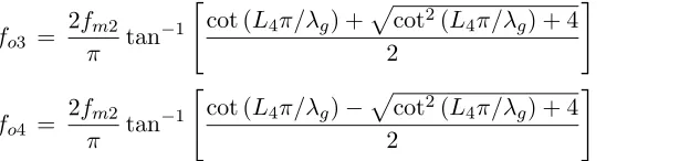
The solutions of Equation (8) is
fo3 =
2fm2 π tan−1
cot (L4π/λg) +
cot2(L
4π/λg) + 4
2
(10a)
fo4 =
2fm2 π tan−1
cot (L4π/λg)−
cot2(L4π/λg) + 4
2
(10b)
However, fo3 is approximately fm2 when L4 is very short whereas fo4 is about 2fm2 according to
Equations (10a) and (10b). Therefore, onlyfo3 is considered for constructing the second passband.
The even-mode resonant frequencies can be obtained by solving Equation (9)
fe3 = fm2 (11a)
fe4 =
2fm2 π tan−1
cot ((L4+ 2Ls2)π/λg)
2
(11b)
It is notable from Equations (10) and (11) that the TMR exhibits triple-mode resonant characteristics (i.e., fo3, fe3, andfe4). Equation (10b) reveals that fo3 is only affected by L4, whereas
Equation (11b) indicates that Ls2 only influences fe4. Therefore, the second wideband can be formed
by shorteningL4 andL4+ 2Ls2 according to Equations (10a) and (11b), respectively.
Figures 2(c) and (d) show the extracted resonant modes of the TMR with variedLs2 andL4. It can
be seen thatf5 can be controlled byLs2 independently, and both f5 and f6 decrease with the increase
of L4. These are consistent with the analysis mentioned above.
2.2. Filter Design
Based on the above analysis, a dual-wideband BPF centered at 2.34 and 3.46 GHz with fractional bandwidths of 25.6% and 21.4% is designed for WLAN/WiMAX applications. Figure 4 depicts the specific configuration of the proposed dual-wideband BPF it is composed of the QMR and TMR analyzed above and a pair of common feedlines. The two resonators are connected by a common via-hole. Also, the stubs are folded for the sake of a compact size.
The design procedure of the first passband using the QMR can be expressed as follows. First, determineL1 andL2 (l1+l2+l3 andl4+l5+l6 in Figure 4) by locatingfo1(fe1) at the CF of the first
passbandfc1. Second, shorten sand Ls1 (s and ls1 in Figure 4) and makefo2 and fe2 approaching to fc1. Then,fo1andfe1 will split under weak coupling between the two loaded open-ended stubs. At last, fo1, fo2, fe1, and fe2 can be allocated within the first passband after fine tuning, and the bandwidth
w0
w1
w2
l1
l2
l3 s
w3
l4
l5
l6
l7
l8
l9
l10
D g1
g2
g3
g4
g5
w4 l
11
l12
ls2
ls1
Figure 4. Configuration of the proposed dual-wideband BPF.
The design procedure of the second passband is similar to that of the first one. First, determine
L3 and L5 (l7 +l8 and l9+l10/2 in Figure 4) by locating fe3 at the CF of the second passband fc2.
Then, shorten L4 and Ls2 (l10 and ls2 in Figure 4) and make fo3 and fe4 approaching to fc2. Finally, fo3, fe3, andfe4 can be distributed within the second passband after fine tuning, and the bandwidth
can be adjusted by controlling the positions of these three modes.
After the two resonators are designed, the proposed dual-wideband BPF can be formed by connecting them with a common via-hole and feeding them with a pair of common input and output. The length of the feedlines are about quarter-wavelength at fc2, and the coupling length between the
QMR and the feedlines is tuned by l1. Figure 5 compares the first, second, and dual passbands with
the QMR, TMR, and both MMRs, respectively. It is noted that each resonator provides an individual wide passband and the dual-wideband performance can be obtained by combining these two resonators, which means the two passbands of the proposed filter can be controlled independently by tuning the design parameters of the corresponding resonator. These are consistent with the above analysis.
3. SIMULATED AND MEASURED RESULTS
For demonstration, a dual-wideband BPF prototype is designed, fabricated, and measured. The substrate used in this work has a dielectric constant of 3.38 a thickness of 0.508 mm, and a loss tangent of 0.0027. All simulation works are carried out by an electromagnetic (EM) simulator HFSS, and measurement works are performed with an Agilent’s N5244A PNA. The optimal dimension parameters are as follows: l1 = 3.84, l2 = 10.16, l3 = 3.4, l4 = 1.6, l5 = 6.8, l6 = 9.75, l7 = 9.85, l8 = 2, l9 = 11.6,
l10= 2.14, l11= 2.3, l12= 10.36, ls1 = 1.23, ls2 = 0.23, w= 1.15, w1 =w2 = 0.4, w3 = 0.8, w4 = 0.2, g1 = 0.13, g2 = 1.06, g3 = 0.4, g4 = 0.1,g5 = 0.2, s= 1, and D= 0.7 (all in mm). The overall size is
only 15.86×16.28 mm2, i.e., about 0.2×0.21λ2g, where λg is the guided wavelength at 2.34 GHz. The
photograph of the fabricated filter is shown in the inset plot of Figure 6.
Figure 6 plots the simulated and measured results of the prototype filter, which indicates that the measured results agree well with the simulated ones. The first and second passbands, which CFs are 2.34 and 3.46 GHz, have measured minimum insertion losses (IL) of 0.84 and 1.21 dB with 3 dB fractional bandwidths (FBWs) of 25.6%, and 21.4%, respectively. The measured return losses (RL) are better than 16.9 and 15.8 dB. The isolation level between the two passbands is about 32.5 dB. Three transmission zeros can be observed at 1.34, 2.8 and 4.46 GHz in Figure 6: TZ1 is created by the weak
source-load coupling, TZ2is introduced by the loaded open-ended stubs of the QMR (L2 in Figure 1(a))
1 2 3 4 5 6 Frequency (GHz)
0
-10
-20
-30
-40
-50
-60
S
-Parameters (dB)
|S 11|
|S 21|
First Band Second Band Dual-Wideband
Figure 5. Simulated S-parameters of the first, second, and dual passbands with the QMR (dash line), TMR (dot line), and both MMRs (solid line).
1 2 3 4 5 6
Frequency (GHz) 0
-10
-20
-30
-40
-50
-60
S
-Parameters (dB)
Simulation Measurement TZ1
2
3
TZ
TZ |S 11|
|S 21|
Figure 6. Simulated and measured results of the proposed dual-wideband BPF.
interference between the two signal paths of the TMR. These TZs improve skirt selectivity and band-to-band isolation level greatly.
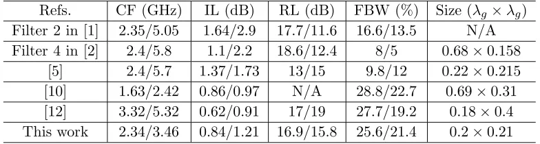
Table 1 summarizes the comparison of the proposed filter with some previously reported works. The proposed dual-wideband BPF exhibits merits of compact size, wide bandwidths, low IL, good in-band and stop-band performance, high skirt selectivity, and independent control of CFs and FBWs. It is worth mentioning that the size of the proposed filter is about 80.4% reduction in comparison with [10].
Table 1. Comparison of the proposed dual-wideband BPF with other reported works.
Refs. CF (GHz) IL (dB) RL (dB) FBW (%) Size (λg×λg)
Filter 2 in [1] 2.35/5.05 1.64/2.9 17.7/11.6 16.6/13.5 N/A Filter 4 in [2] 2.4/5.8 1.1/2.2 18.6/12.4 8/5 0.68×0.158
[5] 2.4/5.7 1.37/1.73 13/15 9.8/12 0.22×0.215 [10] 1.63/2.42 0.86/0.97 N/A 28.8/22.7 0.69×0.31 [12] 3.32/5.32 0.62/0.91 17/19 27.7/19.2 0.18×0.4 This work 2.34/3.46 0.84/1.21 16.9/15.8 25.6/21.4 0.2×0.21
4. CONCLUSION
REFERENCES
1. Guo, L., Z.-Y. Yu, and L. Zhang, “Design of a dual-mode dual-band filter using stepped impedance resonators,”Progress In Electromagnetics Research Letters, Vol. 14, 147–154, 2010.
2. Zhang, S. and L. Zhu, “Synthesis design of dual-band bandpass filters withλ/4 stepped-impedance resonators,”IEEE Trans. Microw. Theory Tech., Vol. 61, No. 5, 1812–1819, May 2013.
3. Li, J., S. S. Huang, and J. Z. Zhao, “Design of a compact and high selectivity tri-band bandpass filter using asymmetric stepped-impedance resonators (SIRs),” Progress In Electromagnetics Research Letters, Vol. 44, 81–86, 2014.
4. Luo, S., L. Zhu, and S. Sun, “A dual-band ring-resonator bandpass filter based on two pairs of degenerate modes,”IEEE Trans. Microw. Theory Tech., Vol. 58, No. 12, 3427–3432, 2010.
5. Chen, F.-C. and J. M. Qiu, “Third-order dual-band bandpass filter with controllable bandwidths using short stub-loaded resonators,” Progress In Electromagnetics Research Letters, Vol. 32, 101– 108, 2012.
6. Li, J., S. S. Huang, H. Wang, and J. Z. Zhao, “Compact dual-band bandpass filter using embedded center-grounded SIR and open-loop resonators,” Progress In Electromagnetics Research Letters, Vol. 49, 9–14, 2014.
7. Chen, F. C., Q. X. Chu, Z. H. Li, and X. H. Wu, “Compact dual-band bandpass filter with controllable bandwidths using stub-loaded multiple-mode resonator,” IET Microw. Antennas Propag., Vol. 6, No. 10, 1172–1178, 2012.
8. Chin, K.-S. and J.-H. Yeh, “Dual-wideband bandpass filter using short-circuited stepped-impedance resonators,”IEEE Microw. Wireless Compon. Lett., Vol. 19, No. 3, 155–157, 2009.
9. Zhou, J.-G., W.-J. Feng, and W.-Q. Che, “Dual-wideband bandpass filter using T-shaped structure based on transversal signal-interaction concepts,”Electron. Lett., Vol. 48, No. 24, 1539–1540, 2012. 10. Xu, J. and W. Wu, “Miniaturised dual-wideband bandpass filter using novel dual-band coupled-line
sections,” Electron. Lett., Vol. 49, No. 18, 1162–1163, 2013.