Televided
MODEL 910 PLUS
TERMINAL
TELEVIDEO®
MODEL 910
PLUS
TERMINAL OPERATOR'S MANUAL
TeleVideo Document No. B300021-001
February 1982
Copyright © 1982 by Tele Video Systems, Inc. All rights reserved. No part of this publication may be reproduced, transmitted, transcribed, stored in a retrieval system, or translated into any language or computer language, in any form or by any means, electronic, mechanical, magnetic, optical, chemical, manual, or otherwise, without the prior written permission of TeleVideo Systems, Inc., 1170 Morse Avenue, Sunnyvale, California 94086.
Disclaimer
Tele Video Systems, Inc. makes no representations or warranties with respect to this manual. Further, Tele Video Systems, Inc. reserves the right to make changes in the specifications of the product described within this manual at any time without notice and without obligation of Tele Video Systems, Inc. to notify any person of such revision or changes.
"Warning: This equipment generates, uses, and can radiate radio frequency energy, and if not installed and used in accordance with the instruction manual may cause interference to radio communications. As temporarily permitted by regulation, it has not been tested for compliance with the limits for Class A computing devices pursuant to Subpart J of Part 15 of FCC Rules, which are designed to provide reasonable protection against such interference. Operation of this equipment in a residential area is likely to cause interference, in which case the user of his own expenses will be required to correct the interference."
Tele Video® is a registered trademark of Tele Video Systems, Inc.
TELEVIDEO SYSTEMS, INC.
1170 Morse Avenue
Sunnyvale, California 94086
LIMITED WARRANTY AND EXTENDED WARRANTY
STATEMENT OF LIMITED WARRANTY
TeleVideo Systems, Inc. ("TeleVideo") warrants to Distributor that its products, except software, will be free from defects in materials and workmanship for 180 days after shipment by TeleVideo. TeleVideo will repair or replace, at its option, any equipment or parts that Tele Video determines were defective when shipped to Distributor. Distributor may pass along to its initial end-user customer ("Customer") the balance of its limited warranty coverage on the terms and conditions stated herein, up to a maximum of90 days beginning on the date of shipment to Customer. This warranty may not be further assigned.
If service is required under this warranty, Distributor or Customer must: (1) notify Tele Video in writing or by telephone of the defect; (2) obtain a Tele Video Return Material Authorization ("RMA") number which must be shown on the outside of all shipping containers and in all correspondence; and (3) send the unit to TeleVideo freight prepaid unless otherwise instructed by TeleVideo. In making repairs, TeleVideo will replace parts as needed on an exchange basis. After repair, Te1e Video will prepay return freight charges.
LIMITED WARRANTY EXCLUSIONS
This limited warranty does not cover losses or damage which occur:
1. In shipment to or from Distributor or Customer.
2. Due to neglect, misuse or any cause other than ordinary use in commercial or industrial applications.
3. Due to adjustment, repair or modifications by other than TeleVideo-authorized personnel.
4. Due to improper environment, excessive or inadequate heating or air conditioning, and electrical power failures, su~ges or other irregularities.
5. Due to other causes beyond the control of Tele Video, including but not limited to natural causes or disas-ters, war, insurrection, civil disturbances, labor disputes, requirements of domestic or foreign govern-ments, and shortage or allocation of materials, utilities or other resources.
Any statements made about Tele Video's products by salesmen, dealers, distributors or agents, unless in writing signed by an officer of TeleVideo, do not constitute warranties, shall not be relied upon by Distributor or Customer and are not part of the contract of sale.
All statements, technical information and recommendations in this document and in any manuals or related documents are believed to be reliable, but the accuracy or completeness thereof is not guaranteed.
TELEVIDEO DOES NOT WARRANT THAT ITS PRODUCTS ARE MERCHANTABLE OR FIT FOR ANY PARTIC-ULAR PURPOSE. THIS LIMITED WARRANTY IS IN LIEU OF ALL OTHER WARRANTIES, EXPRESS, IMPLIED OR STATUTORY. TELEVIDEO MAKES NO WARRANTY WHATSOEVER CONCERNING ANY SOFTWARE PRODUCTS, WHICH ARE SOLD "AS IS" AND "WITH ALL FAULTS."
TELEVIDEO'S LIABILITY, WHETHER BASED ON CONTRACT, TORT, WARRANTY, STRICT LIABILITY OR ANY OTHER THEORY, SHALL NOT EXCEED THE PRICE OF THE INDIVIDUAL UNIT WHOSE DEFECT OR DAMAGE IS THE BASIS OF THE CLAIM. IN NO EVENT SHALL TELEVIDEO BE LIABLE FOR ANY LOSS OF PROFITS, LOSS OF USE OF FACILITIES OR EQUIPMENT, OR OTHER INDIRECT, INCIDENTAL OR CONSE-QUENTIAL DAMAGES. THE FOREGOING LIMITED WARRANTY IS THE EXCLUSIVE REMEDY PROVIDED TO DISTRIBUTOR AND TO CUSTOMER.
EXTENDED WARRANTY
Tele Video offers an Extended Warranty Contract on the same terms and conditions as the original Limited Warranty. To take advantage of this Extended Warranty, you must sign the Extended Warranty Contract and return it, together with full payment, to Tele Video prior to the end of your normal warranty period. The extended warranty lasts for one year; the cost is $75.00.
To renew the extended warranty for another year, the same procedure must be followed.
Shipping charges are not included in the Extended Warranty. This is the only expense you incur.
TABLE OF CONTENTS
LIST OF FIGURES AND TABLES . . . iv
1. INTRODUCTION . . . 1
1.1 Terminal Overview . . . . 1
1.2 How to Use This Manual. . . . 1
1.3 Protect Yourself!. . . . I 2. INSTALLATION . . . 2
2.1 Introduction . . . 2
2.2 Unpacking and Inspecting the Terminal. 2 2.2.1 Shipping Damage Inspection . . . 2
2.2.2 Unpacking the Terminal . . . 2
2.2.3 Inspecting the Terminal . . . 2
2.2.4 Reporting Damage . . . 2
2.2.5 Reshipping the Terminal . . . 3
2.3 Preparing the Site . . . 3
2.3.1 Power Requirements . . . 3
2.3.2 Physical Requirements . . . 3
2.4 Installation. . . . 3
2.4.1 Power Configuration . . . 3
2.4.2 Connecting the Terminal to a Computer System or Modem . . . . 3
2.4.3 Connecting the Terminal to a Printer ... 4
2.4.4 Configuring the Terminal for the Computer and Printer . . . 4
2.4.4.1 Character Sets . . . 4
2.4.4.2 Video Display . . . 6
2.4.4.3 Composite Video Jumper Option . . . 6
2.4.4.4 Current Loop Option . . . 6
2.4.4.5 Additional Modifications . . . 10
2.5 Installation Checklist . . . 10
3. OPERATION . . . 11
3.1 Introduction . . . 11
3.2 Turning on the Terminal . . . 11
3.3 Keyboard Controls . . . 11
3.3.1 Keyboard Layout . . . . 11
3.3.2 Key Functions . . . 11
3.3.3 Cursor Control . . . 14
3.4 Basic Operations. . . . 14
3.4.1 Tab Controls . . . 14
3.4.2 Editing . . . 14
3.4.2.1 Block Mode . . . 14
3.4.2.2 Conversation Mode . . . 14
3.4.3 Sending Data to the Printer . . . 15
4. PROGRAMMING . . . 16
4.1 Introduction . . . 16
4.2 Monitoring Control Commands . . . 16
4.3 FUNCT Key . . . 16
4.4 Addressing and Reading the Cursor ... 17
4.4.1 Addressing the Cursor . . . 17
4.4.2 Reading the Cursor . . . 17
4.5 Visual Attributes . . . 17
4.6 Protect Mode . . . '18
4.6.1 Application . . . 18
4.6.2 Effect . . . 18
4.6.3 Procedure . . . 18
4.6.3.1 Input . . . 18
4.6.3.2 Protection . . . 19
4.7 Tab Programming . . . 19
4.7.1 Setting a Tab . . . , . . . 19
4.7.2 Using Tabs . . . 19
4.7.2.1 Typewriter Tabs (Protected and Unprotected) . . . 19
4.7.2.2 Field Tabs (Protected Only) . . . 19
4.7.2.3 Back Tab . . . 19
4.7.3 Clearing Tabs . . . 19
4.7.3.1 TypewriterTabs . . . 19
4.7.3.2 All Tabs . . . 19
4.8 Editing Controls . . . 19
4.8.1 Edit Modes . . . 19
4.8.1.1 Local Edit Mode . . . 19
4.8.1.2 Duplex Edit Mode . . . 20
4.8.2 Cursor Control . . . 20
4.8.2.1 Cursor Control Codes . . . 20
4.8.2.2 Normal Linefeed . . . 20
4.8.3 Editing Commands . . . 20
4.8.3.1 Character Insert . . . 20
4.8.3.2 Character Delete . . . 20
4.8.3.3 Line Insert. . . . 20
4.8.3.4 Line Delete . . . 20
4.8.3.5 Erase to End of Line . . . 20
4.8.3.6 Erase to End of Line with Nulls . . . 20
4.8.3.7 Erase to End of Screen . . . 20
4.8.3.8 Erase to End of Screen with Nulls . . . 20
4.9 Clear Function . . . 20
4.9.1 Clear Unprotected to Nulls . . . 21
4.9.2 Clear Unprotected to Spaces . . . 21
4.9.3 Clear Screen to Half-Intensity Spaces .. 21
4.9.4 Clear All Data to Nulls . . . 21
4.10 Disabling and Enabling the Keyboard .. 21
4.11 Cursor Attributes . . . 21
4.12 Word Structure, Parity Settings, and 4.13 4.13.1 4.13.2 4.13.3 4.13.4 4.13.5 4.13.6 4.14 4.14.1 4.14.2 4.15 4.15.1 4.15.2 4.16 4.17 4.18 4.19 Stop Bits . . . 21
Send Function . . . .22
Send Line Unprotected . . . 22
Send Screen Unprotected . . . .22
Send Line All. . . . 22
Send Screen All . . . .22
Send Unprotected Message . . . . 22
Send Entire Message . . . .22
Termination Character Selection. . . .22
Page Terminator . . . .22
Line Terminator . . . . 22
Print Function Programming . . . . 22
Transparent Print . . . 23
Extension (Copy) Print. . . . 23
X-On/X-Off Control . . . 23
Data Terminal Ready Control . . . .23
Custom EPROM Applications . . . 23
Bell . . . 23
5. PREVENTIVE MAINTENANCE AND CARE . . . 24
5.1 Care . . . 24
5.1.1 Cleaning . . . 24
5.2 Troubleshooting . . . 24
5.2.1 Testing the Terminal (Self Test) . . . 24
5.3 Repair . . . 27
TABLE OF CONTENTS
5.3.2 Changing the Power Supply Fuses . . . 27
5.4 Technical Assistance . . . . 27
APPENDICES . . . ·27
A. Specifications . . . 27
B. ASCII Code Chart . . . . 29
GLOSSARy . . . ·29
INDEX . . . ·31
OPERATOR'S QUICK REFERENCE GUIDE . . . Inside back cover SWITCH SETTING REFERENCE CHART . . . Inside back cover iv
LIST OF FIGURES
2-1 Location of Screws in Terminal Cover. . . .. 22-2 Dimensions . . . .. 3
2-3 Rear Panel. . . .. 3
2-4 Switch Setting Example . . . .. 6
2-5 Logic Board. . . .. 7
2-6 Interior of Terminal . . . .. 8
2-7 Current Loop Board . . . .. 9
2-8 Current Loop Board in Relation to Logic Board. . . .. 9
3-1 Keyboard Layout . . . .. 11
3-2 Communication Modes . . . 14
3-3 Screen Display . . . 15
4-1 Video Attributes and Monitor Mode . . . 16
4-2 Bit Structure of a Serial Data Word . . . 22
4-3 Print Modes . . . 23
LIST OF TABLES
2-1 P3 (Computer Interface) Pin Connections. . .. 42-2 P4 (Serial Printer Interface) Pin Connections.. 4
2-3 a. Switch Settings . . . .. 5
b. Switch Settings for Baud Rates. . . .. 6
2-4 Switch Settings of SI for Common Word Structures . . . .. 6
2-5 Character Set Jumper Options. . . .. 6
2-6 Possible Current Loop Configurations . . . . .. 9
2-7 RS232C Terminal Interface Jumper Options . . 10
3-1 Function of Keys. . . 12
4-1 Cursor Coordinates . . . .. 17
4-2 Escape Sequences for Visual Attributes . . . .. 18
4-3 Switch Settings for Parity and Data Bits . . . 21
1. INTRODUCTION
This manual will explain how to install, operate, pro-gram, and troubleshoot your new terminal. The manual has been designed to help you use the terminal easily regardless of your previous experience with terminals.
1.1 TERMINAL OVERVIEW
The Model 910 PLUS CRT terminal is a modular-design unit. Its nonglare green screen with high resolution char-acters reduces operator fatigue. Charchar-acters can be green on black or black on green.
The terminal includes many deluxe features. During in-stallation you can change the terminal to one of four lan-guage character sets (English, Spanish, German, or French). Fifteen baud rates are available to fit your sys-tem requirements. An RS232C printer port allows you to connect an auxiliary printer of your choice. An op-tional current loop interface can be added, allowing the terminal to be installed up to 1,000 feet from your com-puter system.
You can select video attributes, transmission modes, and cursor appearance. Additional commands control pro-tected fields, editing modes, monitor mode, handshak-ing protocol, and extension or copy print. Ushandshak-ing a special "FUNCT" key plus an additional character allows you to quickly transmit a preprogrammed command se-quence. Transmission can be conversational or block, editing can be local or duplex.
1.2 HOW TO USE THIS MANUAL
As you progress through the manual, you will find the following chapters:
2. INSTALLATION
Setting up your site for the terminal, the power requirements, unpacking and checking the ter-minal, setting switches to take advantage of the options available, configuring the terminal for your computer system and printer.
3. OPERATION
Turning on the terminal, a description of the keyboard and functions of the keys, using tabs, editing, sending data to the computer and the printer.
4. PROGRAMMING
Controlling the terminal through commands from your computer system: programming special functions, setting visual attributes, monitoring the program, loading and reading the cursor po-sition, adding custom RAM and ROM, disa-bling the keyboard and printer.
5. TROUBLESHOOTING AND
SERVICE
Periodic cleaning and inspection of the termi-nal, troubleshooting simple problems (using a table of symptoms, possible causes, and solu-tions), using self-test, service under warranty.
GLOSSARY
Explanation of terms commonly used in this manual.
APPENDICES
Specifications and reference tables.
INDEX
References to main subsections by subject.
OPERATOR'S QUICK REFERENCE
GUIDE
Lists all control and escape commands.
Each section of the manual is numbered. To find a topic later, look in the index and find the appropriate section.
As you read the manual, you will notice some special symbols at the left margin of the text. These symbols call your attention to information of special importance. The symbols used are:
~o~ General note giving information
/ I , to every operator.
8
Programming note giving infor-mation of special significance to the programmer.
Warning giving information con-cerning the safety of the operator or possible loss of data. When you see this note, STOP and read the note before proceeding!
1.3 PROTECT YOURSELF!
When you install or test the terminal, observe standard safety precautions (as you would with any electrical or electronic equipment). Only qualified service personnel should open the terminal housing. Disconnect all power before performing any inspection or maintenance.
8
Beyond the normal precautions, you should be aware of two additional conditions:
8
2. Even after the power is turned off, charges are re-tained by the CRT and capacitors. Always dis-charge them to ground before touching them. Never reach into the terminal enclosure unless someone capable of giving aid is present.
2. INSTALLATION
2.1 INTRODUCTION
This chapter will tell you how to unpack and check your terminal for damage, check power and site require-ments, and set the power and interface configurations. A brief checklist at the end will make sure you did not skip any part of the installation process.
Once your terminal is installed, you will be ready to op-erate the terminal. You will probably not need to refer to this chapter again unless you move the terminal, re-ship it, or use it with another computer system.
As you start the installation, you will want to have some information about your computer system and its config-uration requirements.
2.2 UNPACKING AND INSPECTING THE
TERMINAL
2.2.1 Shipping Damage Inspection
After the terminal is delivered to you, inspect the ship-ping container as well as the terminal (inside and out) for damage before taking it to your installation site. You should inspect the container for obvious damage before accepting delivery of the terminal. If damage is found, note it on the waybill and require the delivery agent to sign the waybill. Notify the transfer company immedi-ately and submit a damage report to the carrier, your dealer, and to Tele Video. If no exterior damage is found, unpack the terminal and inspect it for hidden damage.
2.2.2 Unpacking the Terminal
Carefully unpack the terminal from the shipping tainer. Avoid using sharp instruments to open the con-tainer. Save the packing container and material for possible use in reshipping the terminal.
2.2.3 Inspecting the Terminal
After you unpack the terminal, inspect it thoroughly for hidden damage and loose components or fittings. The inspection checklist is as follows:
2
1. Remove the terminal cover by removing the screws underneath the front bottom of the keyboard. Lift up the cover carefully.
8
The terminal will now be top heavy and will have a tendency to fall over backwards. Be sure there is sufficient table room.
2. Inspect the keyboard and display cabinet interior for shipping damage.
3. Examine cable harnesses for stress, loose or bro-ken wires, or brobro-ken cable ties.
4. Examine all internally mounted components for loose or missing hardware.
5. Tighten all loose hardware.
6. Clean loose debris from the cabinet interior.
7. Replace the cover. Do not overtighten the screws.
I I
!
Figure 2-1 Location of Screws in the
Terminal Cover
2.2.4 Reporting Damage
If hidden damage is found, immediately notify the trans-fer company of the damage. Save all packing materials for the transfer company's inspection, file a damage re-port with the carrier, and notify your dealer and Tele Video of the damage. Since terms of sale for the terminal are FOB TeleVideo, Sunnyvale, California, TeleVideo is not responsible for any damage which occurred during ship-ment and will not repair this damage under warranty. All
2.2.5 Reshipping the Terminal
Should you need to reship the terminal, follow these procedures:
1. Remove the two screws on the bottom front of the terminal and lift off the cover.
2. Check the integrity of the cabling and security of internal mounting hardware.
3. Replace cover, being careful not to overtighten the screV-IS.
4. Repack the terminal in the original TeleVideo shipping container or other suitable materials.
2.3 PREPARING THE SITE
Before you proceed with the actual installation, make sure you are ready with the proper power and a large enough table.
2.3.1 Power Requirements
• 115 VAC 60 Hertz at 0.5 amp OR
230 VAC 50 Hertz at 0.25 amp
• 55 watts
• NEMA standard 5-15R, 3-prong receptacle (US only)
2.3.2 Physical Requirements
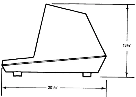
• Flat, level area
• Surface dimensions: 13% inches (33.66 cm) high 16% inches (40.96 cm) wide
20Y16 inches (50.96 cm) deep • Recommended ventilation clearance is 4 inches (10.2
cm) on all sides. Refer to Figure 2-2.
t
13W'
... - - - 20V1S" ---~~
Figure 2-2 Dimensions
2.4 INSTALLATION
The actual installation and set-up consists of only three steps:
1. Configuring the terminal for either 115 or 230 VAC operation.
2. Connecting the terminal to the computer or a mo-dem (and to a printer, if used).
3. Configuring the terminal by setting switches and installing jumper options.
2.4.1 Power Configuration
Depending on your location, the terminal can be config-ured to operate with either 115 VAC (United States) or 230 VAC (international).
115 VAC Configuration-Keep the three-prong plug which is provided with the terminal and make sure your outlet is grounded. If an adapter is used, ground with a pigtail.
230 VAC Configuration-If you are located outside the United States and use 230 VAC power, cut off the US-style three-prong plug provided and install a connector compatible with your local power receptacles. The power cord wires are color-coded as follows:
• Green Earth ground
• Black Primary power (hot)
• White Primary power return (neutral) Set the power select switch (located underneath the terminal) to either 115 or 230 V (Fig. 2-3). You will set Hertz to match your power frequency when you set switch S2.
SWITCH
S2--t~'-f~~ii5l~ii~LsWITCH
SlCONTRAST----:,.*O
POWER SELECT SWITCH---i)""'"
FUSE----,~
AC POWER C O R D - - - - + ¥
Figure 2-3 Rear Panel
2.4.2 Connecting the Terminal to a Computer
System or Modem
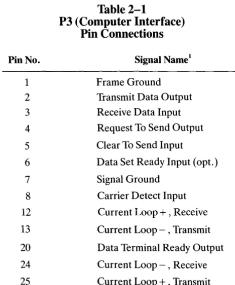
The interface connection to the computer system (main) port is P3, located on the rear of the terminal. The con-nector configuration of P3 is given in Table 2-1.
Pin No. 1 2 3 4 5 6 7 8 12 13 20 24 25 Notes
Table 2-1
P3 (Computer Interface)
Pin Connections
Signal Name1
Frame Ground Transmit Data Output Receive Data Input
Request To Send Output
Clear To Send Input
Data Set Ready Input (opt. )
Signal Ground
Carrier Detect Input
Current Loop
+ ,
ReceiveCurrent Loop - , Transmit
Data Terminal Ready Output
Current Loop - , Receive
Current Loop
+ ,
Transmit1. Reference EIA Standard RS232 for Signal Definitions
2.4.3 Connecting the Terminal to a Printer
Your terminal can be connected to an auxiliary serial printer to make a permanent hard copy of data displayed on the screen. The terminal's serial printer interface al-lows the terminal to be used with most RS232-compati-ble serial printers currently availaRS232-compati-ble on the market, including both character-by-character and buffered printers. The serial printer interface is a 25-pin connec-tor, P4, located on the rear of the terminal. Table 2-2 defines the serial printer interface pin connections.
Pin No. 1 3 6 7 20
Table 2-2
P4 (Serial Printer Interface)
Pin Connections
Signal Name
Protect Ground Transmit Data Data Set Ready Signal Ground Data Terminal Ready
4
2.4.4 Configuring the Terminal for the
Computer and Printer
Two switches (located on the rear of the terminal and shown in Fig. 2-2) allow you to configure the terminal to operate according to the requirements of your com-puter system and printer. This section describes these switch settings.
lbe optional conditions controlled by these switches are:
Baud Rates
You can select any of 15 baud rates according to the requirements of your computer system.
Character Sets
You can select English, French, German, or Spanish character sets.
Hertz
You can set the Hertz switch to match your powerline frequency.
Parity, Stop Bits, and Word Structure
You can set the parity, number of stop bits, and num-ber of bits in the word structure to match the require-ments of your computer system.
Signals
You can connect/disconnect Data Set Ready, Data Carrier Detect, and Data Terminal Ready.
Thansmission
You can select half or full duplex (conversational mode) or block mode.
Set your printer's baud rate to match the computer's baud rate. (This rate is also used for switch SI dipswitches 1 through 4 as described in Table 2-3b.)
Whenever you change any switches, press BREAK twice while holding down the SHIFf key. This allows the soft-ware to scan all new switch positions.
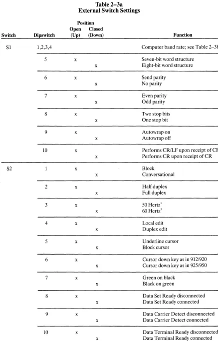
2.4.4.1 Character Sets-You can select any of four pos-sible character sets. The standard set is English. To select another character set, refer to Table 2-5.
<I
n
Ir
ITable 2-3a
External Switch Settings
Position Open Closed
Switch Dipswitch (Up) (Down) Function
SI 1,2,3,4 Computer baud rate; see Table 2-3b
5 x Seven-bit word structure x Eight-bit word structure
6 x Send parity
x No parity
7 x Even parity
x Odd parity
8 x Two stop bits
x One stop bit
9 x Autowrap on
x Autowrap off
10 x Performs CRILF upon receipt of CR x Performs CR upon receipt of CR
S2 1 x Block
x Conversational
2 x Half duplex
x Full duplex
3 x 50 Hertzl
x 60 Hertz!
4 x Local edit
x Duplex edit
5 x Underline cursor
x Block cursor
6 x Cursor down key as in 912/920
x Cursor down key as in 925/950
7 x Green on black
x Black on green
8 x Data Set Ready disconnected x Data Set Ready connected
9 x Data Carrier Detect disconnected x Data Carrier Detect connected
10 x Data Terminal Ready disconnected x Data Terminal Ready connected
NOTES
Table 2-3b
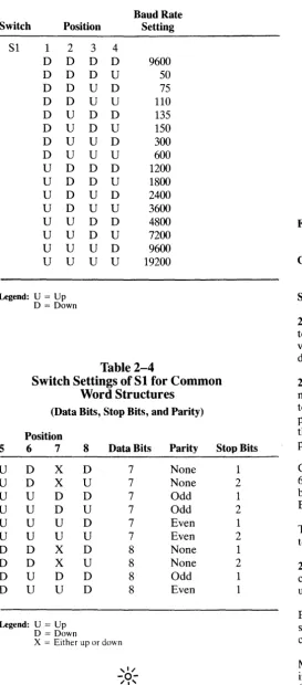
Switch Settings for Computer Baud Rates
Baud Rate Switch Position Setting
Sl 1 2 3 4
D D D D 9600 D D D U 50 D D U D 75 D D U U 110 D U D D 135 D U D U 150 D U U D 300 D U U U 600
U D D D 1200
U D D U 1800
U D U D 2400
U D U U 3600
U U D D 4800
U U D U 7200
U U U D 9600 U U U U 19200
Legend: U = Up
D = Down
Table 2-4
Switch Settings ofSl for Common
Word Structures
(Data Bits, Stop Bits, and Parity)
Position
5 6 7 8 Data Bits Parity Stop Bits
U D X D 7 None 1
U D X U 7 None 2
U U D D 7 Odd 1
U U D U 7 Odd 2
U U U D 7 Even 1
U U U U 7 Even 2
D D X D 8 None 1
D D X U 8 None 2
D U D D 8 Odd 1
D U U D 8 Even 1
Legend: U = Up
D = Down
X = Either up or down
If word structure, parity, or stop bits are set incorrectly, the terminal will only display @ signs when it is turned on.
6
Conversational (down)
~
Half duplex (up) - - - - ' 60 Hertz (down). --~ Duplex edit (down) - - - ' Block cursor (down) - - - '912/920 mode (up) - - - '
Black on green (down) - - - ' DSR connected (down) - - - ' DCD disconnected (up) - - - ' DTR connected (down)
Figure 2-4 Switch Setting Example
Table 2-5
Character Set Jumper Options
French Cut trace between E4 and E5. Ensure that E6 and E7 are connected.
German Cut trace between E6 and E7. Ensure that E4 and E5 are connected.
Spanish Cut trace between E6 and E7 and E4 and E5.
2.4.4.2 Video Display-You can set the terminal display to be green on black (normal) or black on green (re-verse) and cause the cursor to be an underline or a block, displayed as steady or blinking. (See Table 2-3a.)
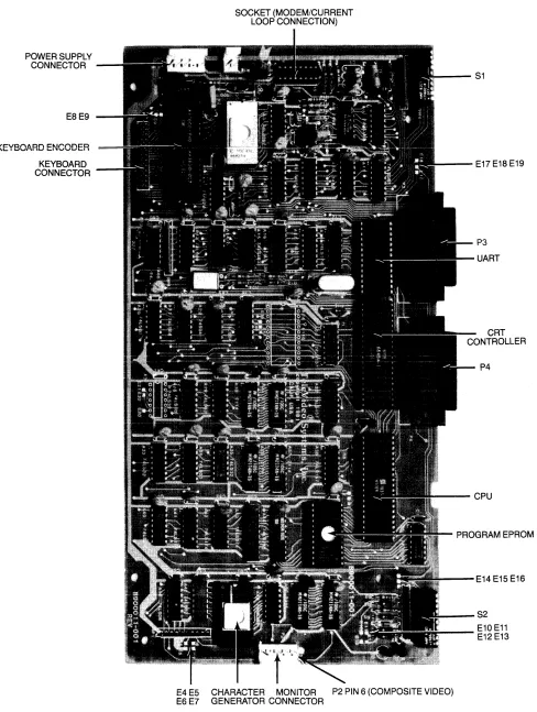
2.4.4.3 Composite Video Jumper Option-To drive a monitor in addition to or other than the terminal moni-tor, modify the logic board (Fig. 2-5) by adding an Am-phenol BNC connector (Part 227169-5) to the rear of the terminal case. (See Fig. 2-6 for recommended placement. )
Connect the center lead of the BNC connector to P2 pin 6 and the BNC ground lead to P2 pin 3. Cut the trace between E10 and Ell. Install a jumper between El2 and E13.
The monitor should not be more than 10 feet from the terminal.
2.4.4.4 Current Loop Option-Installing an optional current loop board enables you to operate the terminal up to 1 ,000 feet from your computer system.
Before you install the optional current loop board, in-spect it for possible shipping damage (i.e., bent pins, cracked board, etc.).
Make cuts and jumpers on the current loop board (shown in Figure 2-7) according to the desired configuration. (Possible configurations are described in Table 2-6).
POWER SUPPLY CONNECTOR
E8E9
KEYBOARD ENCODER
KEYBOARD CONNECTOR
SOCKET (MODEM/CURRENT LOOP CONNECTION)
- - - S 1
---E17E18E19
P3
UART
P4
~--CPU
PROGRAM EPROM
- - - E 1 4 E15 E16
_ _ -S2
_____ E10 E11 E12 E13
E4 E5 CHARACTER MONITOR P2 PIN 6 (COMPOSITE VIDEO)
E6 E7 GENERATOR CONNECTOR
00
POWER SUPPLY
POWER SUPPLY FUSES
S1
P6
-_Figure 2-6 Interior of Terminal
PLACEMENT OF BNC CONNECTOR
- - - S 2
A1a
[I]
0R~1a(i)V440~
-1
68r-o::
o ~ 0R30~ 51KH»
0-i
510Ha
R4 o ~ 0
0-1
4.7K~ 0 -i510 ~CR1 P6 W~ W1
Q 2 Q 3
O .
91 4)O ·
"0 0~
~60
--j4.7K1-0:
;:70
O:~
y
\.Y~O
-1
3.3KH»
0
~:
:W42N2907 CR20 • 914) 0
0
0
0a
rn
0(')0-1 10Kr-o~:
:
~
A20
~ O~O
.914) 0 00
g
o v
~
0 -1100K~ ~O
0
~
OTelt.~ldt..~)
coFigure 2-7 Current Loop Board
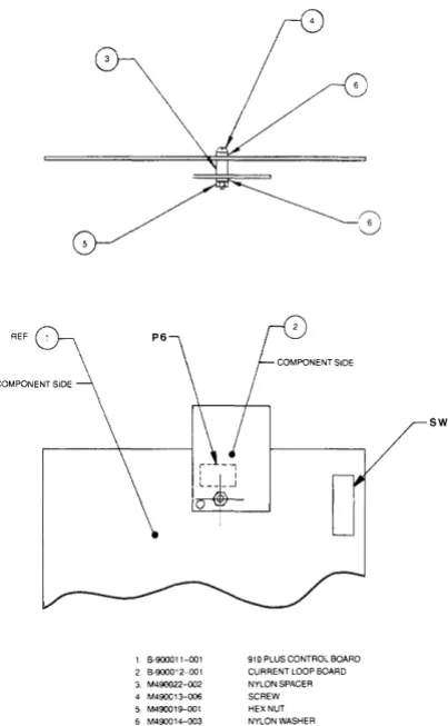
Table 2-6
1 6-900011-001 2 6-90001 2-001 3. M490022-oo2 4 M490013-006 5 M490019-oo1 6 M490014-oo3
;-0
/
910 PLUS CONTROL 60ARD CURRENT LOOP BOARD NYLON SPACER SCREW HEX NUT NYLON WASHER
Figure 2-8 Current Loop Board
in Relation to Logic Board
Possible Current Loop Configurations
Full Duplex Active
Passive
Half Duplex Active
Passive
Notes
Transmit/ Receive
Transmit
Receive
Transmit
Receive
Transmit and Receive
Transmit and Receive
Cut
W2toW3
W6 to W7
None
None
W3toW4
None
Jumper
W1 to W3 W3toW4
W5toW6 W7toW8
None
None
W1 to W2 P3-13 to P3-12
P3-13 to P3-12
1 Active = terminal supplies the current source; passive = computer supplies the current source.
P3 Pin No.
Pin 25-Pin 13+
Pin 12-Pin 24+
Pin 25
+
Pin13-Pin 12+ Pin
24-Pin 25-Pin 24 +
Pin25+ Pin
Insert the current loop board into the 16-pin socket lo-cated on the terminal control board. Refer to Figure 2-3 for socket position; Figure 2-8 shows where to insert the screw, spacer, washer, and nut.
Replace the terminal cover using the screws you re-moved. Be careful not to overtighten the screws.
Connect your computer to the terminal, using a cable with pins as shown in the column labeled P3 Pin No. in Table 2-6.
2.4.4.5 Additional Modifications-Table 2-7 describes other jumper options which will change the terminal's interfaces.
Table 2-7
RS232C Terminal Interface Jumper
Options
1. Standard Set Up (no modifications to printed circuit board)
a. Data Carrier Detect (DCD), P3 pin 8, is used to monitor status of an external modem.
b. Data Terminal Ready (DTR) output is sent to the computer when DTR from printer port is received.
2. Jumper Options
a. Data Set Ready (DSR), P3 pin 6, can be used to monitor the external modem rather than DCD. To install: Cut the trace between E14 and E15. Add a jumper between E15 and E16.
b. Use Request to Send (RTS) to send DTR to com-puter rather than DTR from printer.
To install: Cut the trace between E18 and E19. Add a jumper between E17 and E19.
(Refer to Figure 2-5)
2.5 INSTALLATION CHECKLIST
Before you proceed to the next chapter and turn on the terminal, check to be sure you installed the terminal correctly.
10
1. Did you install the correct power plug for your wall outlet?
2. Did you set the power selector switch to match your power requirements?
3. Is the main interface cable to the computer system properly wired and plugged in?
4. If you are using a printer, did you plug in the printer interface connector?
5. Did you set the switches for the correct • Baud rate (both for terminal and printer)? • Stop bits?
• Word structure? • Parity?
6. Did you set switches for
• 50 or 60 Hertz (to match your powerline/fre-quency requirements)?
• Full or half duplex?
If the answers are YES, then you are ready to proceed with actually using the terminal.
Enter here the serial number, date received, and switch settings. This will expedite any technical conversations about your terminal.
Serial Number _ _ _ _ _ _ _ _ _ _ _ _ _ _ _
Date Received _ _ _ _ _ _ _ _ _ _ _ _ _ _ _
Switch Settings Used:
(Enter U or D for Up or Down)
UfD
UfD
SI
1
S2
1
2
2 _
3
3
4
4
5
5
6
6
7
7
8
8
9
9
3. OPERATION
3.1 INTRODUCTION
This chapter will lead you step-by-step through the op-eration of the terminal. Even if you have never used a computer terminal before, you will be able to use the terminal easily if you read this chapter carefully. If you are a programmer, you will want to continue on to Chap-ter 4, which covers additional information for program-ming a computer to interface with your terminal.
In this chapter you will learn about:
• Turning on and adjusting the terminal's display screen
• Using the various keys on the keyboard
• Directing data to the computer system and the printer through send commands
• Setting tabs
• Communicating with your computer system
3.2 TURNING ON THE TERMINAL
Turn on the terminal as follows:
1. Make sure the ON/OFF switch at the back of the terminal (Figure 2-3) is OFF.
2. Plug the terminal cord into a grounded outlet (115 VAC in United States).
3. Push the end of the rocker power switch marked with a white dot. The terminal should beep within one second, indicating that power is on and the CPU has initialized the terminal. After another 10 to 15 seconds, the cursor should appear in the upper left corner of the screen (home).
4. If the cursor does not appear at the home position, press the home key on the keyboard. If the cursor
still does not appear, check the contrast control at the rear of the terminal (Figure 2-3).
5. Adjust the contrast control for the desired screen intensity.
6. Follow the sign-on protocol required by your com-puter system.
7. Refer to Chapter 5 if the installation does not pro-ceed smoothly.
3.3 KEYBOARD CONTROLS
In addition to standard alphanumeric typewriter keys, your terminal has several keys which perform special op-erations. These special keys can be used in conjunction with your computer to allow:
• Modifying action on other keys
• Editing
• Entering preprogrammed data
Each key on the keyboard is actually a switch. Some-times two keys can be used with any alpha or numeric keys to provide a totally different message to the com-puter. When used together, these keys control the gen-eration of data sent to the computer system and the receipt and printing of information.
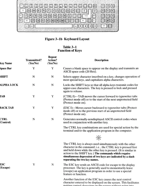
3.3.1 Keyboard Layout
Figure 3-1 illustrates the keyboard layout. The character keys highlighted in Figure 3-1a include all alphabetic characters (a through z), numbers (0 through 9), punc-tuation marks, and mathematical symbols.
3.3.2 Key Functions
Table 3-1 summarizes the function of the special keys which are highlighted in Figure 3-1 b. Many of these keys are also listed in the Operator's Quick Reference Guide on the inside back cover.
Key Name
Space Bar
SHIFT
ALPHA LOCK
TAB
BACK TAB
CTRL (Control)
ESC (Escape)
Transmitted? (YeslNo)
Y
N
N
y
y
N
y
Figure 3-1b Keyboard Layout
Repeat Action? (Yes/No)
Y
N
N
y
y
N
N
Table 3-1
Function of Keys
Description
Causes a blank space to appear on the display and transmits an ASCII space code (20 Hex).
Selects upper character inscribed on a key, changes operation of most special keys, and capitalizes alpha characters.
Locks the SHIFT keys so that all alpha keys transmit codes for upper-case characters. The key is pressed to lock and pressed again to release.
(CTRL/I)-TAB moves the cursor forward to typewriter tabs (Protect mode off) or to the start of the next unprotected field (Protect mode on).
(ESC I)-Moves cursor backward to typewriter tabs (Protect mode off) or to the previous start of an unprotected field (Protect mode on).
Generates normally-nondisplayed ASCII control codes when used in conjunction with another key.
The CTRL key combinations are used for special action by the terminal and/or the application program in the computer.
The CTRL key is always used simultaneously with the other character in the command; i.e., the CTRL key is pressed first and held down while the other key is pressed. (It is similar in action to the SHIFT key.) The commands which require simultaneous depression of two keys are indicated by a slash separating the two key names.
The ESC key sends an ASCII code for escape to the display processor. The key is generally used to momentarily leave (escape) an application program in order to use a special feature or function.
Another function of the ESC key causes the next control character entered to be displayed on the screen. This facilitates putting control characters on the screen without going into monitor mode.
Table 3-1
Function of Keys
Repeat
Transmitted? Action? Description Key Name (Yes/No) (YeslNo)
,I"
-0-"I'
The ESC key is used in conjunction with one alphanumeric character in the command sequence; i. e., the ESC key is pressed and released before the second key is pressed.
Although escape sequences appear here with a space before the alphanumeric character, this space is not to be entered as part of the sequence. It is included only for the sake of clarity.
RETURN/ Y N (CTRLIM)-The RETURN and ENTER keys perform the ENTER same function. They send the ASCII code for a carriage return
(CR) to the display or computer. The communication mode used causes the terminal to transmit a CR (or CRlLF) to the computer and/or the cursor to be moved to the first unprotected position.
If the entire current line is protected, the code moves the cursor to the next unprotected position on the page.
,I"
-0-"I'
The terminal features an auto wraparound function which eliminates the need to manually enter a carriage return and a linefeed at the end of each 80-character line.
HOME
YIN
N (CTRL/ A)-Moves cursor to first unprotected character position on the page.LINEFEED Y Y (CTRL/J)-The LINEFEED key sends an ASCII code (OAH) for a linefeed (LF) to the computer. The code causes the terminal to transmit an LF code to the computer and the cursor to be moved down one line on the screen in half duplex, or echoed by the computer in full duplex.
BACKSPACE~
YIN
Y (CTRL/H)-Moves cursor one character to the left.i
YIN
Y (CTRL/K)-Moves cursor up one line.~
YIN
Y (CTRL/J or CTRL/V)-Moves cursor down one line. If the cursor is on the bottom line of the screen, the code has no ef-fect. The code transmitted is determined by setting of switch S2.~
YIN
Y (CTRL/L)-Moves cursor one character to the right.DEL Y Y The DEL key sends an ASCII DEL character to the computer. (Delete) This is usually interpreted by the computer as a character erase
code.
BREAK Y N Transmits a 250-millisecond break pulse to the computer.
Clear Space
YIN
Y Replaces all unprotected characters on the page with spaces. When pressed the same time as SHIFT (ESC *), it clears the entire page to nulls and turns off protect and half intensity modes.PRINT N N The PRINT key toggles the extension print mode on or off.
3.3.3 Cursor Control
The lighted rectangular block which appears on the screen indicates the entry spot for the following characters to be typed. It is called a "cursor." During typing, the cur-sor moves from left to right. As it reaches the end of a line, it "wraps around" to the beginning of the next line.
If you place the cursor over a character which you have already typed, the character within the cursor will be changed into a reverse image within the cursor. (If the characters have been green on a black background, the cursor will appear as a green rectangle around a black character. )
The movement of the cursor is easy to control. To move the cursor, press one of the cursor control keys marked with an arrow. The cursor will move in the direction of the arrow until you release the key. To return the cursor quickly to the top left position on the screen, press HOME. The cursor will now be in column one, line one.
,I"
-0-"I'
If you are in local edit mode, cursor movement will not be transmitted to the computer.
The cursor display may appear anyone of five ways. See 4.11.
3.4 BASIC OPERATIONS
This section describes various options available to you as you use the terminal:
• Editing data
• Tab controls
• Communicating with your computer system
• Printing
3.4.1 Tab Controls
You can set regular typewriter-style tabs or (if you are using protect mode as described in 4.6) field tabs. Refer to 4.7 for complete instructions on setting, using, and clearing tabs.
3.4.2 Editing
Should you need to change text on the screen, you can delete a line (either partially or completely) or the dis-play (either partially or completely). This will give you space to enter the correct text. Deletions will start with the column position of the cursor. The terminal can also modify screen data using character insert/delete and line insert/delete. These both start at the character position also. Commands for editing are described in 4.8.
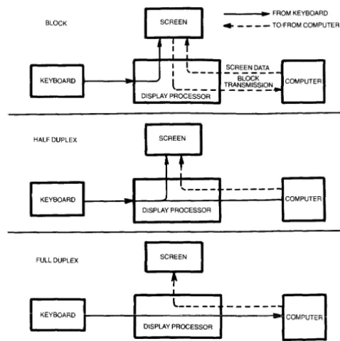
You can select one of three transmission modes by switch settings or using escape sequences. The three modes
14
available are block, half duplex (conversation), and full duplex (conversation). The communications flow caused by these modes are illustrated in Figure 3-2.
_ _ _ _ FROM KEYBOARD
BLOCK • _ _ _ - TO/FROM COMPUTER
HALF DUPLEX
1 - - _ . 0 1 - - " ' - - - + - - - " ' 1 COMPUTER DISPLAY PROCESSOR
FULL DUPLEX
9
Il
KEYBOARD JI---1---+-~---iIlotCOMr-UTERI
L ____ _DISPLAY PROCESSOR
Figure 3-2 Communication Modes
3.4.2.1 Block Mode-Operating in the block mode gen-erally consists of entering or changing text locally. In this mode, the terminal sends the results to the screen. When you are satisfied with the results of the data entry or change, you can enter an escape sequence to send the data to the computer. Block mode allows you to make all corrections before transmission.
To enter block mode, enter
ESCB
If switch S2 is set for block mode, the terminal will revert to conversation mode when an ESC C is received or entered.
To enter conversation mode, enter
ESCC
The terminal is conversationai in either haH or full du-plexmodes.
Half Duplex Mode
The half duplex mode sends keyboard entries to the screen and to the computer at the same time.
Full Duplex Mode
The full duplex mode sends keyboard entries to the com-puter only. If the computer is programmed to act upon a code received from a keyboard entry, it may echo the result back to the terminal. For example, if the "A" is pressed on the keyboard, the computer will probably send the "A" back to the screen.
~ ~ ,
""
....
..
"""" ~
.
;,; i
..
s
ill!
-1Il
..
, " , - , : :~~
': -"",,
t . ' . ' ,
.
...
3.4.3 Sending Data to the Printer
When the printer is printing on a continuous basis, it is an extension of the line from the computer to the ter-minal-this mode of printing is thus called extension or copy all.
To start extension printing, either press the PRINT key or enter
ESC@
To stop printing, press PRINT again or enter
ESCA
You can also send information from the computer to the printer without displaying it on the screen. This is called transparent mode.
Section 4.15 describes commands used for transparent print.
.. • .. ~,: ~ ""'!"';".... , .... ' ~I : • ,,,,' _ .. :
~, l : ~ ~ ~ , " w
4. PROGRAMMING
4.1 INTRODUCTION
Your computer program can completely control your terminal by transferring the appropriate ASCII codes. This chapter tells you how to translate keyboard func-tions into remote control funcfunc-tions.
Unless otherwise specified in the text, all control code sequences are transmitted to the terminal to elicit the response associated with the code.
4.2
MONITORING CONTROL
COMMANDS
You can monitor control commands in several ways:
• Activate the monitor mode without transmitting the monitor mode code itself to the computer
• Transmit the monitor mode code to the computer
To enable monitor mode without transmitting that code to the computer, enter
CTRL/1
To terminate this mode, enter
CfRL/2
To enable monitor mode via the computer, enter
ESCU
MONITOR MODE CODES
CHARACTER SETS
HALF INTENSITY
BLANK REVERSE
REVERSE
BLINK REVERSE
NORMAL VIDEO
BLANK NORMAL
BLINK NORMAL
BLANK BLINK
REVERSE UNDERLINE
BLANK REVERSE UNDERLINE
BLINK REVERSE UNDERLINE
BLANK BLINK REVERSE
NORMAL UNDERLINE
BLANK NORMAL UNDERLINE
BLINK NORMAL UNDERLINE
S1 S2 XS DON'T CHANGE
<I illl!
This must be echoed by the computer or monitor mode will not be activated.
To terminate the display of the control commands, enter either
ESC uorESCX
Figure 4-1 illustrates the monitor mode codes.
4.3 FUNCT KEY
Using the FUNCT (function) key in combination with any key enables you to quickly transmit a three-character sequence of commands.
To enter a function command, press the FUNCT key and at the same time press a key. The first code which is trans-mitted will always be
SOH (Control A)
The second code will be the ASCII code of the depressed key. The third code will always be a CR (Table 2-3).
Program your computer's input/output string routine to catch the entire string and then process it (unless you are using an interrupt-driven computer, in which case you do not need to worry about data being lost).
Figure 4-1 Video Attributes
4.4 ADDRESSING AND READING THE
CURSOR
The computer can tell the terminal where to position the cursor with a four-character escape sequence. This is called addressing or loading the cursor.
4.4.1 Addressing the Cursor
To address the cursor, enter
ESC =
Then enter two more characters to represent the abso-lute row or line and column where the cursor will rest. Using Table 4-1, find the ASCII code representing the desired row. Note that the line number can not be greater than 24. Enter the appropriate ASCII code. Next find the ASCII code corresponding to the desired column position (1 through 80 possible) and enter that code. For example, if you want to program the cursor to go to Row 9, Column 50, enter
ESC = (Q
4.4.2 Reading the Cursor
The computer can also read the cursor's row and coiumn position. To read the cursor's position, enter
ESC?
Following the cursor coordinates (row and column), the terminal will transmit a CR.
4.5 VISUAL ATTRIBUTES
You can define the appearance of each line on the screen (a whole line or only part of aline). Each line must be defined separately (except half intensity). Several attri-butes can be used on each line (i.e., blinking set at the beginning followed by underlining set later in the line).
Reverse Video Changes background of screen on that line to the reverse of that which appears on power ON. If screen is normally black with green characters, this line will now be green with black characters. 1
Table 4-1
Cursor Coordinates
CURSOR POSITIONING
POSITION ASCII CODE POSITION ASCII CODE POSITION ASCII CODE RorCI Transmitted C Transmitted C Transmitted
1 Space 33 @ 65
2 ! 34 A 66 a
3 35 B 67 b
4 # 36 C 68 c
5 $ 37 D 69 d
6 % 38 E 70 e
7 & 39 F 71 f
8 40 G 72 g
9 41 H 73 h
10 42 I 74
11 43 J 75 j
12 + 44 K 76 k
13 45 L 77 I
14 46 M 78 m
15 47 N 79 n
16 / 48 0 80 0
17 0 49 P 81 P
18 1 50 Q 82 q
19 2 51 R 83
20 3 52 S 84
21 4 53 T 85
22 5 54 U 86 u
23 6 55 V 87 v
24 7 56 W 88 w
25 8 57 X 89 x
26 9 58 y 90 y
27 59 Z 91 z
28 , 60 [ 92 {
29 < 61
'"
93I
30 62 ] 94 }
31 > 63 1\ 95
32 ? 64 96 DEL/RUB
Notes
Half Intensity Changes intensity to half of normal on a character-by-character basis.
Half intensity differs from other visual attributes in that once it is set, it affects all characters entered (regardless of cur-sor position) until it is turned off.
Underline Creates a solid line below all characters on the line (including the line created by the underscore key).1
Blink Causes all characters on the line to blink. 1
Blank All data entered on the line will be invis-ible to you but will print out and be transmitted to the computer. (A typical application might be payroll
infor-. )1 matIon.
Note
1. Attribute starts with cursor position and continues until another attribute or end of line is encountered.
Figure 4-1 illustrates the visual attributes.
4.5.1 Setting
To set a visual attribute, place the cursor one position
before you want the attribute to start. Attributes occupy a character position. If you want the whole line changed, place the cursor at column one before entering the at-tribute command (ESC Gn).
Table 4-2
Escape Sequences for
Visual Attributes
Description
Normal video (green on black) Blank (invisible normal video) Blink
Blank (invisible blink)
Reverse video (black on green) Blank (invisible reverse video) Reverse and blink
Blank (invisible reverse blink) Underline
Blank (invisible underline) Underline and blink
Blank (invisible blink underline) Underline and reverse
Blank (invisible underline reverse) Underline and reverse and blink Blank (invisible underline reverse blink) Escape Sequence ESC GO ESCGl ESCG2 ESCG3 ESCG4 ESCG5 ESCG6 ESCG7 ESCG8 ESCG9 ESCG: ESCG; ESCG< ESCG = ESCG> ESCG? 18
4.6 PROTECT MODE
4.6.1 Application
Using protect mode during the creation of a page allows you to protect designated areas of the page from future change by the operator and control the transmission of those areas.
Using protect mode is actually a two-step process: input and protection.
A typical application would be the creation of a form, leaving blank spaces for later entry or variable informa-tion. Were the form headings not protected by protect mode, they would be vulnerable to change or accidental deletion as the form was being filled in.
4.6.2 Effect
Protected areas appear on the screen at half the regular intensity. The cursor is not able to enter a field which has been protected, but will instead advance across that area to the first unprotected field when the operator enters ~
or~. Linefeed,
t
,or ~ may, however, move the cursor to the protected field. The screen does not scroll up in protect mode. If the whole screen is protected, the cur-sor will go to the home position and will not move.Protect mode affects cursor action during tabulating, ed-iting, sending, and printing.
4.6.3 Procedure
4.6.3.1 Input-Individual areas (fields) which will be given blanket protection from later change are created using protected writing mode.
<I 1011 I
Information must be input using this procedure if it is to be protected later.
To start protected writing, position the cursor where the first protected character is to be located.
Enter
ESC)
This turns on protected writing mode (also called half intensity). Until the mode is reset, each character en-tered is displayed at half intensity.
Enter the information for that area of the screen. Proofread the entry and change if necessary.
End data entry in that area by entering
ESC(
This turns off the protected writing mode (half intensity) .
4.6.3.2 Protection-When all areas to be protected have been entered correctly, the whole screen is ready to be protected from change (protect mode on). Once this protection is given, the cursor will not be able to enter those areas unless the protection is removed.
To start protect mode, enter
ESC&
....:1 11111 I
The position of the cursor is irrelevant during this escape sequence.
Protect mode protects all visual attribute codes within the defined protected area from overwriting or erasure. All data within protected areas is also protected.
To remove protect mode (protect off), enter
ESC'
4.7 TAB PROGRAMMING
As briefly described in Chapter 3, the cursor may be moved on the screen to preset typewriter-style tabs or, if protect mode is on, to field tabs. This section describes how to set, use, and clear both types of tabs.
4.7.1 Setting a Tab
To set a tab, move the cursor to the column position where you want a tab. Enter
ESCl
Be sure you enter a numeral one, not a lower case L.
When protect mode is on, this ESC 1 code generates a vertical column of half-intensity spaces from the cursor position down to the first write-protected character or to the end of the page, whichever is first.
When protect mode is off, the code sets a typewriter-style column tab.
4.7.2 Using Tabs
4.7.2.1 Typewriter Tabs (Protected and Unprotected)-When the protect mode is off, CTRL/I causes the cursor to advance to the next typewriter-style tab set. If no tabs are set, the code has no effect and the cursor will not move.
When the protect mode is on, the cursor is moved to the first unprotected character following the next protected field.
4.7.2.2 Field Tabs (Protected Only)-With protect mode on, ESC i causes the cursor to move to the first unpro-tected character following the next prounpro-tected field.
With protect mode off, this code has no effect.
4.7.2.3 Back Tab-When protect mode is off, ESC I causes the cursor to go back to the previous tab position set. If no tabs are set or if the cursor is on the first tab position, this code moves the cursor to the first column on the line.
If protect mode is on, ESC I moves the cursor back to the start of the first preceding unprotected field. If no preceding positions exist, the cursor will not move.
If the cursor is at the first unprotected position on the page, the code has no effect. If no protected fields exist, home position is considered the start of an unprotected field.
4.7.3 Clearing Tabs
4.7.3.1 Typewriter Tabs-You can clear a typewriter tab by putting the cursor on the tab position you wish to clear and entering
ESC2
This code has no effect when protect mode is on.
4.7.3.2 All Tabs-To clear all tabs, enter
ESC 3
The position of the cursor when this code is entered is not important.
4.8 EDITING CONTROLS
The editing control sequences and a description of their functions follow:
8
Use of the editing commands may result in the loss of data. Read the following explanations of the editing con-trol functions carefully.
4.8.1 Edit Modes
The edit modes which are described in this section can be selected either with the switches on the rear of the terminal or with control codes.
There are two edit modes available: local edit and duplex edit.
4.8.1.1 Local Edit Mode-Operating in local edit mode enables you to change the text using the edit keys (CLEARSPACE, BACKSPACE,
i,
~,~,(,-,
TAB, HOME, and BACK TAB) without transmitting these keys or any changes caused by these keys to the com-puter. To enter local edit mode, enterAll other keys will operate normally while local edit is on.
4.8.1.2 Duplex Edit MoTo set the edit keys de-scribed in 4.8.1.1 to operate in the mode set for the alphanumeric keys, enter
ESC I (lower case "L")
For example, if the terminal is set for half-duplex oper-ation, both the alphanumeric and edit keys will operate in half duplex mode.
4.8.2 Cursor Control
The cursor control key operation is described in 3.3.3. Escape and control sequences may be sent from the com-puter to perform the various cursor functions.
4.8.2.1 Cursor Control Codes-The cursor control codes and a description of their functions are described below.
Cursor Up. CTRL/K moves the cursor up one line Cursor Down. Depending on the switch settings, CTRL/V or CTRL/J moves the cursor down one line.
If the cursor is on the bottom line of the screen and switch 2 dipswitch 6 is down (925/950 mode), the code has no effect.
Cursor Left. CTRL/H is the same as BACKSPACE; it moves the cursor left to the next unprotected posi-tion on the page. If the cursor is currently in the first column of the line, it will move to the last column of the preceding line. If the cursor is currently at the first unprotected position on the screen, the code has no effect.
Cursor Right. CTRL/L moves the cursor right one column. If the cursor is at column 80, it moves the cursor to the first column of the next line. With pro-tect mode off, it causes a scroll if the cursor is at col-umn 80 of the last line. With protect mode on and the cursor at the last unprotected position on the page, the cursor will move to the first unprotected position.
Carriage Return. CTRL/M moves the cursor left to column 1 of the current line. If protect mode is on, it moves the cursor to the first unprotected position of the next unprotected field.
Cursor HOME. CTRU 1\ moves the cursor to the first unprotected character on the page.
New Line. CTRLI _ (underline) causes the terminal to perform a CR and a LF.
4.8.2.2 Linefeed-With protect mode off, CTRL/J or linefeed (LF) advances the cursor to the next line on the page. If the cursor is at the bottom of the screen, a LF causes a new line of data to appear at the bottom of the screen and results in the loss of the top line of data on
20
the page (shifts the cursor down). The new line contains spaces.
If the cursor is at the bottom of the screen with protect mode on, LF moves the cursor to the top of the screen at the current column position. If that position is protected, it then moves the cursor to the next unprotected position.
4.8.3 Editing Commands
4.8.3.1 Character Insert-ESC Q causes the character at the cursor to move right one column and enters a space character at the cursor position, The character at column 80 is lost. If protect mode is on, this control will insert from the cursor position to the end of the line or to the first protected field.
4.8.3.2 Character Delete-ESC W deletes the character at the cursor position and moves all following characters left one position. At the end of the delete function, a space character is written into the last position on the line. If protect mode is on, character delete operates only from the cursor position to the end of the unprotected field or line.
4.8.3.3 Line Insert-With protect mode off, ESC E in-serts a line consisting of spaces at the cursor position. This causes the cursor to move to the start of the new line and all following lines to move down one line, resulting in the loss of the last line on the screen. If protect mode is on, a line insert command has no effect.
4.8.3.4 Line Delete-When protect mode is off, ESC R deletes the line at the cursor position and all following lines move up one line. The cursor will move to column 1 of the line and spaces will be loaded into the last line of the screen. When protect mode is on, this code has no effect.
4.8.3.5 Erase to End of Line-ESC T erases all unpro-tected characters from the cursor to the end of the line (or field, if protect mode is on) and replaces them with spaces. If half intensity is on, half-intensity spaces will replace the erased characters.
4.8.3.6 Erase to End of Line with Nulls-ESC t erases all characters from the cursor position to the end of the line or the end of an unprotected field and replaces them with null characters.
4.8.3.7 Erase to End of Screen-ESC Y replaces unpro-tected characters from the cursor position to the end of the screen with spaces. If half intensity is on, erased char-acters will be replaced with half-intensity spaces.
4.8.3.8 Erase to End of Screen with Nulls-ESC y erases all unprotected characters from the cursor position to the end of the screen and replaces them with null characters.
4.9 CLEAR FUNCTION
4.9.1 Clear Unprotected to Nulls
ESC : clears all unprotected data on the screen to the null character.
4.9.2 Clear Unprotected to Spaces
ESC; or ESC
+
or CTRL/Z clears all unprotected data on the screen to spaces. If half intensity is on, the screen will be cleared to half-intensity spaces.4.9.3 Clear Screen to Half-Intensity Spaces
ESC, clears all unprotected data on the screen to half-intensity spaces.
4.9.4 Clear All Data to Nulls
ESC
*
clears all data on the screen to nulls and resets the half intensity and protect modes.4.10 DISABLING AND ENABLING THE
KEYBOARD
You can disable all keyboard functions by remote com-mands from the computer. Once the keyboard is dis-abled, it can only be enabled once again by another remote command from the computer.
S
If your computer system echoes all codes, the keyboard may be accidentally disabled.
To disable the keyboard remotely, enter
ESC#
While the keyboard is disabled, all keys are disabled ex-cept FUNCT, PRINT, BREAK, CTRLIl, and CTRL/2.
To subsequently enable the keyboard, the terminal must receive an ESC" or you must press BREAK twice while holding down the SHIFT key to reset the terminal
completely.
4.11 CURSOR ATTRIBUTES
The cursor display may appear anyone of five ways. To set the cursor display, enter the control code for the de-sired attribute. Type the code in the exact sequence shown below: Attribute Not displayed Blinking block Steady block Blinking underline Steady underline Code ESC.O ESC.1 ESC.2 ESC.3 ESC.4
4.12 WORD STRUCTURE, PARITY
SETTINGS, AND STOP BITS
Each computer system has its own method for checking the transmission of characters from the terminal to verify
receipt. In Chapter 2 you were shown how to set the switches in the terminal to match the requirements of your computer system. Since these settings may be of importance in your programming, they are discussed in more detail here.
The first bit of the transmission is always used as a start bit to tell the computer that a character will be transmit-ted. (This is not part of the character code.) This start bit is always a one. A one may also be referred to as true or
mark or high. A zero bit can also be called afalse, space,
or low.
Following the start bit, the terminal will now send either a 7- or 8-bit character code. These are data bits.
To verify correct receipt of the character code, comput-ers may now require that the next bit received serve as a check on the transmission. This is called parity. Several methods are used, varying from system to system. The methods used are listed in Table 4-3.
Following any parity bit required, the terminal will also send (as set by the switch settings) either one or two stop bits to signal the end of the character code transmission. Stop bits are always ones.
Figure 4-2 shows the structure of a serial data word.
Switch SI Dipswitch 7 S 5 6 5 NOTES
Table 4-3
Switch Settings for Parity
and Data Bits
Position
Up Down Parity Description
x ODD Requires that the total number of valid data bits be odd.
x EVEN Terminal will add a one as necessary to make the total valid data bits sent even.
Xl One (or Requires that a one be MARK or sent in the parity TRUE) position.
x 2
ZERO (or Requires that a zero be SPACE or sent in the parity FALSE) position.
x SEND Allows an odd or even parity to be sent.
x NONE (or Does not require a parity NO) bit to be sent.
x Causes 7 data bits to be sent.
Start Data, parity, stop bit
Data bit Stop bit or not used
I
I
I
Figure 4-2 Bit Structure of a Serial Data Word
4.13 SEND FUNCTION
Once you have entered and edited data or text, you can transmit it to the computer by entering an escape se-quence to send specific data.
4.13.1 Send Line Unprotected
ESC 4 sends all unprotected data on a line from column I through the cursor position. This code also sends an FS code (IC Hex) as a field delimiter in place of each pro-tected field and an end-of-text character at the end of the send transmission.
4.13.2 Send Screen Unprotected
ESC 5 sends all unprotected data on the screen from home through the cursor position. It sends an FS code (IC Hex) as a field delimiter in place of each protected field. The code also sends a line delimiter at the end of a line and an end-of-text character at the end of the send transmission.
4.13.3 Send Line All
ESC 6 sends all data from the first column through the cursor position. It also sends ESC) at the beginning of each protected field and ESC ( at the end of each pro-tected field. If the character at the cursor position is pro-tected, the terminal sends ESC ( to the computer. The code sends an end-of-text character at the end of the send transmission.
If the data to be sent includes attribute characters, these will be sent also [the terminal will automatically include the suitable escape sequences (ESC Gn)].
4.13.4 Send Screen All
ESC 7 sends all data on the screen from home through the cursor position. It also sends ESC) at the start of each protected field and ESC ( at the end of each pro-tected field. If the character at the cursor position is pro-tected, the terminal sends an ESC (to the computer. This code also sends a line delimiter at the end of each line and the end-of-text character at the end of the send transmission.
22
4.13.5 Send Unprotected Message
ESC S sends all unprotected data bracketed by the start of text (STX) and end of text (ETX) codes displayed on a screen. After the data is sent, the terminal positions the cursor at the ETX code. If the screen contains on STX codes, transmission begins from the home position.
If the screen contains no ETX code, the terminal sends to the end of the screen and positions the cursor at home after the data is sent. If the screen contains neither an STX nor an ETX code, the entire screen will be sent. The code sends an FS code (IC Hex) as a field delimiter in place of protected fields. It also sends line delimiters at the end of each line and an end-of-text delimiter at the end of the send transmission.
4.13.6 Send Entire Message
ESC s is similar in effect to an ESC S except that pro-tected fields delimited by start-propro-tected field (ESC
0
and end-protected field (ESC)) are also transmitted.4.14 TERMINATION CHARACTER
SELECTION
4.14.1 Page Terminator
At the completion of each send sequence, a CR is sent to the computer. This termination character may be changed to any ASCII code by entering
ESCx4NN
where NN
=
any two ASCII characters. For NN, two characters must be entered. Use a NULL (CTRL/@) as a filter code.For example, to change the termination character to ETX, enter
CTRL/C (ETX) CTRL/@ (NULL)
4.14.2 Line Terminator
At the end of each line, a US (IFH) is transmitted. To change the line termination character, enter
ESCxlNN
where NN = any two ASCII characters.
4.15 PRINT FUNCTION PROGRAMMING
As discussed in Chapter 3, there are two methods of print commands available: transparent and extension.
The protocol described above functions in eit