Volume 2010, Article ID 293572,13pages doi:10.1155/2010/293572
Research Article
Blind Estimation of the Phase and Carrier Frequency Offsets for
LDPC-Coded Systems
Rodrigue Imad,
1Sebastien Houcke,
2and Mounir Ghogho (EURASIP Member)
3, 41Alcatel-Lucent Bell Labs, INRIA, 91620 Nozay, France
2Institut T´el´ecom; T´el´ecom Bretagne, Universit´e Europ´eenne de Bretagne, UMR CNRS 3192 Lab-STICC, Technopˆole Brest-Iroise, CS 83818, 29238 Brest Cedex 3, France
3School of Electronic and Electrical Engineering, University of Leeds, Leeds LS2 9JT, UK 4International University of Rabat, Rabat, Morocco
Correspondence should be addressed to Rodrigue Imad,[email protected]
Received 2 September 2010; Accepted 24 November 2010
Academic Editor: Magnus Jansson
Copyright © 2010 Rodrigue Imad et al. This is an open access article distributed under the Creative Commons Attribution License, which permits unrestricted use, distribution, and reproduction in any medium, provided the original work is properly cited.
We consider in this paper the problem of phase offset and Carrier Frequency Offset (CFO) estimation for Low-Density Parity-Check (LDPC) coded systems. We propose new blind estimation techniques based on the calculation and minimization of functions of the Log-Likelihood Ratios (LLR) of the syndrome elements obtained according to the parity check matrix of the error-correcting code. In the first part of this paper, we consider phase offset estimation for a Binary Phase Shift Keying (BPSK) modulation and propose a novel estimation technique. Simulation results show that the proposed method is very effective and outperforms many existing algorithms. Then, we modify the estimation criterion so that it can work for higher-order modulations. One interesting feature of the proposed algorithm when applied to high-order modulations is that the phase offset of the channel can be blindly estimated without any ambiguity. In the second part of the paper, we consider the problem of CFO estimation and propose estimation techniques that are based on the same concept as the ones presented for the phase offset estimation. The Mean Squared Error (MSE) and Bit Error Rate (BER) curves show the efficiency of the proposed estimation techniques.
1. Introduction
The past few years have seen an increasing demand for efficient and reliable digital communication systems. In order to protect the transmitted data from noise, error-correcting codes are introduced in the transmission scheme. Turbo codes and Low-Density Parity-Check (LDPC) codes have proven their efficiency in detecting and correcting errors, even at low signal-to-noise ratios (SNR) [1, 2]. However, a degradation in performance of these codes is expected when a phase offset and a Carrier Frequency Offset (CFO) are present in the system. The CFO is usually due to a possible carrier frequency mismatch or a relative motion between the transmitter and the receiver.
In the literature, two synchronization approaches are often used to blindly estimate the phase offset: the “Non-Data-Aided” (NDA) and the “Hard Decision Di-rected”
(HDD) [3]. These approaches assume that only the modu-lation type used for transmission is known by the receiver, which is generally the case. Recently, code-aided algorithms for phase offset estimation have been developed, as in [4,
5]. Another approach consists of joint phase recovery and decoding, as in [6]. As for the frequency offset estimation, several techniques were proposed in the literature. In [7,
CFO and the Doppler for transmissions using MPSK (M-ary Phase Shift Keying) modulations. Performance of the NLLS estimator for low SNR was studied in [12]. Although the NLLS estimator is very effective in the BPSK (Binary Phase Shift Keying) modulation case, its performance degrades for higher-order modulations.
In this paper, we present effective blind techniques for phase and frequency offsets estimation. The proposed algorithms are based on the calculation and minimization of functions of the syndrome elements of the error-correcting code used in the transmission scheme. These algorithms were inspired by a Maximum a Posteriori (MAP) based blind frame synchronization method previously proposed in [13, 14] and applied to codes having a sparse parity check matrix. We showed that frame synchronization can be obtained by minimizing the Log-Likelihood Ratios (LLR) of the syndrome calculated at each position of a sliding window applied to the received sequence. In this paper, we consider perfect frame synchronization and we investigate the behavior of functions of the LLR of the syndrome when a phase offset or/and a CFO are present in the system. Syn-chronization is achieved by optimizing these functions. Note that synchronization techniques proposed in this paper are based on properties of the parity check matrix of the error-correcting code used during the transmission. However, the synchronization procedure is accomplished before applying the decoder and its performance is independent of the decoder efficiency. This explains the difference between our algorithms and the code-aided ones, which need information provided by the decoder to achieve synchronization.
The paper is organized as follows. InSection 2we present the proposed phase offset estimation method for a BPSK modulation (Section 2.2) then for higher-order modulations (Section 2.3).Section 3shows how to use similar criteria in order to estimate the CFO of the system. Simulation results are presented inSection 4where we apply our algorithms to LDPC codes. Finally,Section 5concludes the work.
2. Proposed Blind Phase Offset
Estimation Method
2.1. Context of Our Study. We consider in this paper that the
system we want to synchronize is using an LDPC code of rate
ρ = (nc −nr)/nc. This code is defined by its parity check matrixH of sizenr ×nc, wherenc represents the length of a codeword andnr the number of parity relations. In this section, we assume that an unknown phase offset is present in the system. Then, a received sample can be written as
r(k)=b(k)ejθ0+w(k), (1)
where b(k) is the kth coded, modulated and transmitted symbol and w(k) is a white complex Gaussian noise. We denote byθ0the phase offset of the channel.
The proposed method of blind estimation of the phase offset is based on a MAP approach in the sense of maximizing the probability that a phase θcorresponds to the correct phase offset, given a number, say N, of received samples.
In other words, our target is to maximize the following a
posterioriprobability:
Pr
θ
r
, (2)
wherer=[r(1),. . .,r(N)]T.
In order to guarantee identifiability, we should verify that in the noise-free case, once we correct the received samples by
θ, the resultant blocks are valid codewords. The easiest way to check whether a block corresponds to a valid codeword or not is by calculating its syndrome which is obtained according to the parity check matrixHof the code [14]. Each element of the syndrome is calculated using one parity check equation defined by one row ofH. The resultant syndrome can be written as
S=[S(1),S(2),. . .,S(nr)]. (3)
Whenθ=θ0, the probability of having a verified parity check
equation is greater than when θ /=θ0. In the logarithmic
domain, these probabilities can be expressed in terms of LLRs.
LetΛbe the LLR of the syndrome calculated for a phase
θ. It is defined by
Λθ=logPr[[S(1),. . .,S(nr)]=/0] Pr[[S(1),. . .,S(nr)]=0]
. (4)
We showed in [14] that for codes having a sparse parity check matrix,Λ(θ) can be approximated by
Lθ= nr
k=1
l(S(k)), (5)
where l(S(k)) is the LLR of a syndrome element and is defined by
l(S(k))=log
Pr[S(k)=1] Pr[S(k)=0]
. (6)
Note that in the noise-free case, ifθ=θ0, all theS(k)k=1,...,nr are equal to zero, and henceL(θ0) becomes minimum.
According to the decoding algorithm of LDPC codes [15],l(S(k)) is written as
l(S(k))=(−1)uk+1atanh ⎛ ⎝uk
j=1
tanh ⎛ ⎝r
kj
2 ⎞ ⎠ ⎞
⎠, (7)
where
r(i)= 2
σ2r(i) (8)
is the LLR of the ith received sample and σ2 is the total
the code and the position of the jth nonzero element in this
kth row, respectively. In this paper and for simplicity reasons, the value ofukis assumed to be even.
Inspired by [14,16], we approximate (7) by
l(S(k))=(−1)uk+1 ⎛ ⎝uk
j=1
signrkj ⎞
⎠ min j=1,...,uk
rkj. (9)
In this way, no a priori information about the Gaussian channel is required to calculate the LLR of a syndrome element [17].
2.2. Proposed Estimation Method for the BPSK Modulation
Case. Having defined the LLR of a syndrome and explained
its importance in verifying whether a block corresponds to a valid codeword or not, we describe next our proposed algorithm of blind estimation of the phase offset.
In this section, we consider that the transmitter is sending a binary sequence of coded data and is using a BPSK modulation. Once a codeword is received, we rotate its samples by a phaseθ. We get
rθ(k)=r(k)e−jθ. (10)
Then, by studying the real and imaginary parts of each of the resulting complex-valued samples, we obtain two expressions of the syndrome, one for each part. Therefore, we compute the functionsLR(θ) andLI(θ), which are the statistical mean of approximations of the LLR of the syndrome obtained from the real and imaginary parts of the rotated received samples
rθ(k), respectively. From (9), we express functionsLR(θ) and
LI(θ) as
LR
θ=E
⎡ ⎣nr
k=1
⎛ ⎝(−1)uk+1
⎛ ⎝uk
j=1
signRrθ
kj
⎞
⎠
× min j=1,...,uk
Rrθ
kj ⎞ ⎠ ⎤ ⎦,
(11)
LI
θ=E
⎡ ⎣nr
k=1
⎛ ⎝(−1)uk+1
⎛ ⎝uk
j=1
signIrθ
kj
⎞
⎠
× min j=1,...,uk
Irθ
kj ⎞ ⎠ ⎤ ⎦,
(12)
whereE[·] denotes the statistical expectation operator.
−4 −3 −2 −1 0 1 2 3 4
−300
−250
−200
−150
−100
−50
0
LR(θ˜) LI(θ˜)
˜ θ−θ0
Figure1:LR(θ) andLI(θ) versus the phase offset estimation error (θ−θ0).
Note that (11) and (12) can be estimated by
LR
θ=1
K
K−1
i=0
⎡ ⎣nr
k=1
⎛ ⎝(−1)uk+1
⎛ ⎝uk
j=1
signRrθ
kj+inc
⎞
⎠
× min j=1,...,uk
Rrθ
kj +inc ⎞ ⎠ ⎤ ⎦,
LI
θ=1
K
K−1
i=0
⎡ ⎣nr
k=1
⎛ ⎝(−1)uk+1
⎛ ⎝uk
j=1
signRrθ
kj+inc
⎞
⎠
× min j=1,...,uk
Rrθ
kj +inc ⎞ ⎠ ⎤ ⎦,
(13)
where K is the number of codewords used to calculate the statistical expectation of functions LR and LI. In the remaining of this paper and for simplicity reasons, we assume thatK=1.
We plot inFigure 1the variation ofLR(θ) andLI(θ) in terms of the phase estimation error (θ−θ0), in a noise-free
channel. The LDPC code used here has a lengthnc = 512 bits, rateR=0.5 anduk=4 nonzero elements in each row of its parity check matrix. For this simulation, we makeθvary from−πtoπ. We notice fromFigure 1that, for an estimation error equal to zero (i.e.,θ= θ0),LR(θ) is minimum while
LI(θ) is maximal. Therefore, in order to estimate the phase offset of the channel, we define a new cost function given by
Jθ=LR
θ−LI
θ. (14)
The variation ofJ(θ) in terms of (θ−θ0) is shown inFigure 2
−300
−200
−100
0 100 200 300
−4 −3 −2 −1 0 1 2 3 4
J
(
˜θ)
˜ θ−θ0
Figure2:J(θ)=LR(θ)−LI(θ) versus the phase offset estimation error (θ−θ0).
J(θ) is minimum at a phaseθ=θ0(moduloπ). Therefore,
minimizing this function gives an estimation of the phase
θ0 with an ambiguity of π. In other words, the proposed
estimation algorithm estimates the phase offset by
θ=argmin θ
Jθ. (15)
It is clear from the shape of the curve inFigure 2thatJ(θ) has only one minimum located at θ = θ0. Hence, the
optimization problem is not that complicated and it can be solved using Gradient descent method [18].
Gradient Descent Method. When applied to a functionh(x),
Gradient descent method takes the form of iterating
xi+1=xi−i∂h (xi)
∂xi , (16)
until a stop criterion is reached. ∂h(xi)/∂xi represents the partial derivative ofhwith respect toxi.idenotes the step of the descent procedure. A simple example ofiisi =1/Ki, where K is a constant that can be adjusted and i is the number of the current iteration. Thexireached at the final iteration of the Gradient descent algorithm is the solution of the optimization problem.
In our case, we want to minimize function J(θ). As shown in (16), the Gradient descent method requires the computation of the gradient of the function to minimize. According to (11) and (12), the gradients of functionsLR(θ) andLI(θ) cannot be computed. However, these functions are approximations of the LLR of the syndrome obtained from
(9). Using the exact expression of the LLR of a syndrome given in (7), we define
LRe
θ
=E
⎡ ⎣nr
k=1
⎛
⎝(−1)uk+1atanh ⎛ ⎝uk
j=1
tanh ⎛ ⎝R
⎛ ⎝rθ
kj
σ2
⎞ ⎠ ⎞ ⎠ ⎞ ⎠ ⎞ ⎠ ⎤ ⎦,
(17)
LIe
θ
=E
⎡ ⎣nr
k=1
⎛
⎝(−1)uk+1atanh ⎛ ⎝uk
j=1
tanh ⎛ ⎝I
⎛ ⎝rθ
kj
σ2
⎞ ⎠ ⎞ ⎠ ⎞ ⎠ ⎞ ⎠ ⎤ ⎦.
(18)
LRe(θ) and LIe(θ) are proportional to LR(θ) and LI(θ), respectively. Hence, Minimizing (14) is now equivalent to minimizing
Je
θ=LRe
θ−LIe
θ. (19) The variance of the noise σ2 being unknown and for
simplicity reasons, its value can be replaced by 1 in (17) and (18), as proposed in [19]. The partial derivative ofJe(θ) is computed inAppendix Aof this paper.
2.3. Proposed Estimation Method for the Higher-Order
Modu-lation Case. The algorithm proposed in the previous section
is only valid for a BPSK modulation. We propose in this section a blind phase offset estimation technique for higher-order modulations, based on the same concept as the one previously proposed in this paper. The proposed algorithm, which is based on an iterative procedure, is described below. At each iteration, we rotate the higher-order modulated samples by a phase θ, we get rθ(k). Then, inspired by an approximation given in [20], we propose to estimate the LLR of each bit of a rotated sample by
Γaθ(k−1)q+i
=min γ∈Q γi=0
rθ(k)−γ
2
σ2 −minγ∈Q
γi=0
rθ(k)−γ
2
σ2 , i=1,. . .,q,
(20)
where Q is the set of symbols of the higher-order modu-lation, γ is a possible symbol of Q, and γi is the ith bit among theqbits constituting a symbol. The variableaθ(k) represents the kth coded bit obtained after rotating the received samples byθ.
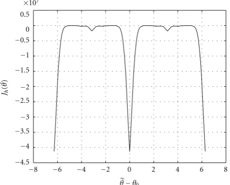
Inspired by [14], we compute a new cost function given by
Jh
θ=E
⎡ ⎣nr
k=1
⎡ ⎣(−1)uk+1
uk
j=1
signΓaθ
kj
× min j=1,...,uk
Γaθ
kj ⎤ ⎦ ⎤ ⎦.
−8 −6 −4 −2 0 2 4 6 8
−4.5
−4
−3.5
−3
−2.5
−2
−1.5
−1
−0.5
0 0.5
×107
Jh
(
˜θ)
˜ θ−θ0
Figure3:Jh(θ) versus the phase offset estimation error (θ−θ0).
Figure 3shows the variation of Jh(θ) in terms of (θ−θ0),
in a noise-free channel for the same LDPC code previously introduced but this time we consider the 16-state Quadrature Amplitude Modulation (16-QAM) case. It is clear that optimizing function Jh(θ), which is minimum at a phase
θ =θ0, gives an estimate of the phase offset of the channel.
Moreover, the periodicity of functionJh(θ) being equal to 2π, minimizing this function gives an exact estimate of the phase, without any ambiguity.
According to (20) and (21), function Jh(θ) is not differentiable. Hence, Gradient descent method cannot be applied to resolve the optimization problem in question. In this paper, we propose to use the Simulated Annealing algorithm [21,22] for minimizing functionJh(θ). Note that the phaseθ0can be also estimated by a brute force search on
functionJh.
Simulated Annealing Algorithm. In its original form, the
Simulated Annealing algorithm is based on the analogy between the simulation of the annealing of solids and the problem of solving large combinatorial optimization prob-lems. Annealing is the process of heating a solid and cooling it slowly in order to remove strain and crystal imperfections. During this process, the free energy of the solid is minimized. The initial heating is necessary to avoid becoming trapped in a local minimum. Every function can be viewed as the free energy of some system and therefore, studying and imitating this process should solve our optimization problem.
Lethbe the function to be minimized. The iterative Sim-ulated Annealing algorithm can be summarized as follows:
Initialize:x,T0, anda, wherexis the solution of the
minimization problem,T0 is the initial temperature
andais the temperature decrease coefficient.
Loop: beginning of the iterative procedure,
generate a variablezfollowing a uniform distri-bution.
(i) if (h(z)−h(x)≤0), then acceptx=z
(ii) else
(iii) generate a variableufollowing a uniform distri-bution between 0 and 1,
(iv) acceptx =zif (exp(−((h(z)−h(x))/T0ai)) ≥
u), whereiis the current iteration number.
Exit: when the maximal number of iterations or a stop criterion is reached.
3. Proposed Blind Carrier Frequency Offset
Estimation Method
3.1. Case I: No Phase Offset is Present in the System. We
consider in this section that the phase offset θ0 = 0 and
an unknown CFO is present in the system. In this case, a received sample is equal to
r(k)=b(k)ej2πk f0Ts+w(k). (22) For the moment, a BPSK modulation is assumed to be used and our target is to estimate the CFO f0, which is assumed
to be in the range of a few percents of the symbol rate 1/Ts. In this paper, we suppose that f0 is uniformly distributed
between−0.1/Tsand 0.1/Ts. The CFO estimation technique that we propose in this section is based on the same concept as the one we already proposed for phase estimation. First of all, we compensate the CFO of the system by a frequency candidate f. The resultant samples are then written as
rf(k)=r(k)e−j2πkf Ts. (23)
Then we compute our new cost functionLR(f), which is the same as (11) but calculated this time from samplesrf(k). This function is written as:
LR
f=E
⎡ ⎣nr
k=1
⎛ ⎝(−1)uk+1
⎛ ⎝uk
j=1
signRrf
kj
⎞
⎠
× min
j=1,...,uk Rrf
kj ⎞ ⎠ ⎤ ⎦.
(24)
We show in Appendix B that the cost function LR(f) is minimum for f = f0. Hence, the proposed technique
estimates the CFO of the system by
f =argmin f
LR
f. (25)
−0.1−0.08−0.06−0.04−0.02 0 0.02 0.04 0.06 0.08 0.1
−300
−250
−200
−150
−100
−50
0 50
LR
(
˜f)
˜ fTs−f0Ts
Figure4:LR(f) versus the frequency offset estimation error (f Ts−
f0Ts).
of length nc = 512 bits, rate R = 0.5 and uk = 4. From this figure, it is clear thatLR(f) has a global minimum for
f = f0(i.e., f Ts−f0Ts=0) and the value of this minimum is equal to−256 (for the LDPC code used in this simulation,
nr = 256). This validates the theoretical study presented
Appendix B.
Let us make a zoom on a part of function LR(f). We can clearly observe that for f Ts − f0Ts=/0, the curve of
LR(f) contains many local minima that are not random fluctuations. Therefore, it is clear that the optimization problem that we have is not that simple to solve and not any minimization algorithm may work. The Simulated Annealing algorithm presented in the previous section might be a solution for our problem. However, due to the particular shape of functionLR(f), the optimization problem can also be solved by a brute force search or by proceeding in two steps (coarse and fine steps) as proposed in [23].
3.2. Case II: An Unknown Phase Offset Is Present in the System.
In this section, we assume that, in addition to the unknown CFOf0, an unknown phase offsetθ0is present in the system.
In these conditions, a received sample can be written as:
r(k)=b(k)ej(2πk f0Ts+θ0)+w(k), (26)
and our target is to estimate the frequency f0independently
of the unknown phaseθ0.
When an unknown phase offset θ0 is present in the
system, optimizing function LR(f) doest not guarantee anymore an estimation of the CFO f0. In order to solve this
problem, we propose to use function LI(f), which is the
same asLR(f) but calculated from the imaginary parts of the received samples:
LI
f=E
⎡ ⎣nr
k=1
⎛ ⎝(−1)uk+1
⎛ ⎝uk
j=1
signIrf
kj
⎞
⎠
× min
j=1,...,uk Irf
kj ⎞ ⎠ ⎤ ⎦.
(27)
The main idea of the proposed estimation method is to combineLR(f) andLI(f). For CFO estimation, we propose to use
Lf=LR
f+LI
f. (28)
The rationale behind the use of the above cost function is described as follows. In the absence of noise, when f = f0,
and since theuk’s are assumed even and theb(k)’s are real-valued, we have that
LR
f0
(θ0unknown)= |cos(θ0)|LR
f0
(θ0=0),
LI
f0
(θ0unknown)= |sin(θ0)|LR
f0
(θ0=0).
(29)
Hence, sinceθ0 is unknown andLR(f0) may be zero when
θ0 = π/2, estimating the CFO usingLR(f) alone may fail. Choosing the cost function in (28) overcomes this problem sinceLRandLIcannot be both zero, regardless ofθ0. Further,
in the presence of noise, considering bothLRandLIreduces the effects of noise. Thus, the proposed estimate of the CFO of the system is given by
f =argmin f
Lf. (30)
Note that the shape of functionL(f) is similar to the one ofLR(f) plotted inFigure 4. Once again, the optimization problem that we have cannot be solved by a Gradient descent method. We simply propose here to optimize functionL(f) using the Simulated Annealing algorithm.
3.3. A Reduced Complexity CFO Estimation Algorithm.
We will see in the Simulation Section that the proposed algorithms of CFO estimation provide very good results. However, their main disadvantage is in the optimization part. In order to reduce the complexity of the proposed methods, our goal is now to decrease the computation time of the optimization algorithm. Therefore, before applying the proposed CFO estimation technique, we propose to run first of all an existing algorithm that estimates the frequency offset by [10]
fest=
1 4πDTsArg
⎧ ⎨ ⎩
N−1
k=D
(r(k)r∗(k−D))2 ⎫ ⎬
⎭, (31)
in the case of a BPSK modulation. Note thatNdesignates the number of samples used to estimate the frequency offset and
consider thatN =nc, wherencis the length of a codeword, and we chooseDto be equal to 1.
The output frequencyfestobtained by (31) serves as the
first input frequency for the optimization algorithm (the Simulated Annealing, e.g.) used in the proposed frequency offset estimation technique. Moreover, as the number of iterations of the optimization algorithm increases with the size of the search interval of f0, we propose to reduce
this search interval from [−0.1/Ts, 0.1/Ts] to [fest−3
σ2 est,
fest + 3
σ2
est], where σest2 is the theoretical variance of the
frequency offset estimation of the existing algorithm. In [24], the authors compute an approximate expression ofσ2
est by
assuming the frequency offset to be null. Their expression is also valid for small values of f0Ts. In this paper, we derive a new expression ofσ2
est without making the assumption of a
null frequency offset. For large values ofN, we show that (see
Appendix C)
σ2 est=
1
π2T2
sN
2σ4
e + 4σe6+ 2σe8
, (32)
whereσ2
e is the variance of each part of the complex additive white Gaussian noise.
The CFO estimation algorithms presented above are applied in the BPSK modulation case. However, one can apply the same procedure presented inSection 2.3and adapt it so that it can be used to estimate the CFO for higher-order modulations.
4. Simulation Results
We present in this section our simulated results to analyze the performance of the proposed blind phase offset and CFO estimation techniques when applied to LDPC codes. The plotted curves were obtained by Monte Carlo simulations.
4.1. Phase Offset Estimation. We consider first of all the
problem of estimating the phase offset of the channel when no CFO is present in the system. In order to evaluate the effectiveness of the proposed technique, we compared it to three different techniques of blind phase offset estimation. The first one is the HDD generally used as a reference for many phase recovery algorithms [3]. The HDD algorithm estimates the phase offset of the channel by
θHDD=arg
⎛ ⎝N
k=1
r(k)d(k)∗ ⎞
⎠, (33)
where {d(k)}k=1,...,N are the hard decision estimations for
N transmitted symbols obtained from the received samples {r(k)}k=1,...,N. (∗) designates the conjugate of a complex number. The second algorithm to which the proposed method was compared is a classical phase offset estimation algorithm that was presented in [25] for MPSK modulations
and in [26] for other types of modulations. This algorithm estimates the phase offset of the channel by
θP= 1
Parg
⎡
⎣Eb(k)∗PN k=1
r(k)P ⎤
⎦. (34)
For a MPSK modulation, the variablePin the above equation is equal toM. As for QAM modulations, it was shown in [26] that the optimal phase estimator is obtained by settingP=4. Without loss of generality, we assume that
Eb(k)2=1, (35)
which corresponds to a constellation with an average energy equal to unity. For both algorithms described in (33) and (34), we choseN=ncin our simulations.
The proposed method was also compared to a technique that was recently proposed in [27]. Using (11) and (12), this technique estimates the phase offset of the channel by
θ=Arctan
±LI(0)
LR(0)
. (36)
Let us consider first of all a system using a BPSK modulation.
Figure 5 shows the MSE curves versus Eb/N0 once the
proposed and existing phase offset estimation techniques are applied to a system that is using an LDPC code of length
nc = 512 bits, rateR = 0.5 and having uk = 4 nonzero elements in each row of its parity check matrix. For the Gradient descent algorithm, we chose a step i = 1/30i and we fixed the number of iterations to 50. Note that we could also compute an optimal step and decrease the number of required iterations. It is clearly seen fromFigure 5
that the phase offset estimation algorithm proposed in this paper is the most powerful algorithm among all the studied techniques. An MSE of around 4.10−3is reached at anE
b/N0
equal to 3 dB.
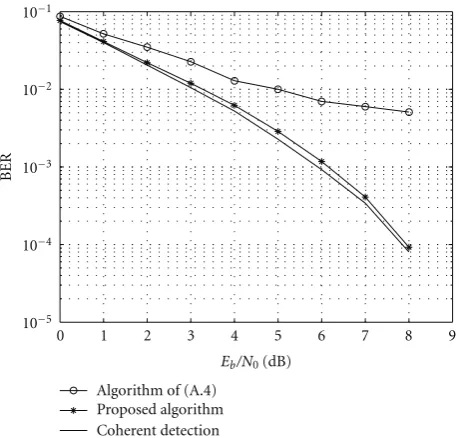
In order to evaluate the robustness of the proposed phase offset estimation technique, we plotted in Figure 6the Bit Error Rate (BER) curves obtained by decoding the previous LDPC code using the Belief Propagation (BP) decoder, which was applied after achieving the estimation procedure. Eight iterations of the BP algorithm were realized and the tested LDPC code was the same as the one previously used. From
Figure 6, it is clear that applying the classical algorithm of (34) yields a big degradation in the BP performance. However, when we apply the proposed phase estimation technique, we obtain a curve that is very close to the one of the coherent detection case. For a BER equal to 10−3, the gap
between the two curves is lower than 0.2 dB.
Let us now analyze the performance of the blind phase estimation technique proposed inSection 2.3of this paper for higher-order modulations. For this, we consider a system using a 16-QAM and the same LDPC code previously used. In the QAM case, the classical estimation algorithm of (34) becomes
θQAM=1
4arg ⎛ ⎝N
k=1
(r(k))4 ⎞
0 1 2 3 4 5 6 7 8 9 10 10−4
10−3
10−2
10−1
100
Eb/N0(dB)
MSE
HDD algorithm
Proposed algorithm Algorithm of (A.2) Algorithm of (A.4)
Figure 5: MSE of the phase offset estimation when no CFO is present in the system-BPSK modulation.
0 1 2 3 4 5 6 7 8 9 10−4
10−3
10−2
10−1
Eb/N0(dB)
Proposed algorithm Coherent detection 10−5
BER
Algorithm of (A.4)
Figure6: BER curves obtained after estimating the phase offset of the system and applying the BP decoder-BPSK modulation.
where r(k) in this case are the received QAM-modulated symbols. The MSE curves obtained after synchronization are plotted inFigure 7. Once again, it is seen that the proposed technique presents very good performance. For only 100 iterations of the Simulated Annealing algorithm, an MSE of around 5·10−3is obtained at aE
b/N0equal to 4 dB. Note also
that for the QAM case, the classical algorithm of (37) gives an estimation of the phase with an ambiguity ofπ/2. However, as shown inFigure 3, the proposed technique calculates an exact estimation of the phase, without any ambiguity.
0 1 2 3 4 5 6 7 8 9 10
Eb/N0(dB)
MSE
Proposed algorithm 10−4
10−3
10−2
10−1
100
Algorithm of (A.2)
Figure7: MSE of the phase offset estimation for a 16-QAM.
4.2. Carrier Frequency Offset Estimation. We consider now
the problem of CFO estimation when an unknown phase offset is present in the system. For each run of Monte Carlo simulations, a CFO between−0.1/Tsand 0.1/Tsand a phase offset between−π/2 andπ/2 were randomly chosen.
Figure 8 shows the Mean Squared Error (MSE) curves of the proposed and existing methods when applied to an LDPC code of length nc = 512 bits, rate R = 0.5 and having uk = 4 nonzero elements in each row of its parity check matrix. It is clear that when we increase the number of iterations of the Simulated Annealing (SA) algorithm, the performance of the proposed frequency estimation technique is improved. Moreover, applying an exhaustive search to find the minimum of (28) instead of using a Simulated Annealing gives very good results. The proposed method clearly outperforms the classical one summarized by (31). An MSE of around 5·10−8is reached for anE
b/N0equal
to only 2.5 dB.
In order to reduce the number of iterations of the Simulated Annealing algorithm, we initialized the frequency input by the one estimated with the classical algorithm, as described in Section 2.1 of this paper. The corresponding curve is also plotted inFigure 8. As we can see, initializing the input frequency tofestand reducing the search interval as
proposed (algorithm denoted by “class + prop.” inFigure 8), yields better results for a fixed number of iterations. For only 700 iterations of the Simulated Annealing, we can now reach an MSE of 7·10−8for anE
b/N0equal to 3 dB.
We also plotted in Figure 8 the performance of the NLLS algorithm, which estimates the CFO of the system by maximizing the periodogram ofr(k)Pas follows [11]:
fNLLS=
1
PTsargmaxf N1
N−1
k=0
r(k)Pe−2jπkf T s
2
0 2 4 6 8 10−10
10−9
10−8
10−7
10−6
10−5
10−4
10−3
10−2
Eb/N0(dB)
MSE
Prop, SA 700 it Class + prop, SA 700 it Prop, SA 1500 it Prop, SA 3000 it Prop, exhaustive search NLLS,N=128 samples NLLS,N=256 samples NLLS,N=512 samples Classical meth. of (37)
Figure8: MSE of the carrier frequency offset estimation for a BPSK modulation.
0 1 2 3 4 5 6 7 8
10−8
10−7
10−6
10−5
10−4
10−3
10−2
Eb/N0(dB)
MSE
Proposed algorithm
NLLS,N=128 samples (512 bits) NLLS,N=256 samples (1024 bits)
Figure9: MSE of the carrier frequency offset estimation for a 16-QAM.
0 1 2 3 4 5 6 7 8 9 10 10−2
10−1
Eb/N0(dB)
MSE
HDD algorithm
Proposed algorithm 101
100
Algorithm of (A.2) Algorithm of (A.4)
Figure 10: MSE of the phase offset estimation obtained after applying the CFO estimation algorithm-BPSK modulation.
It is clear that for a BPSK modulation, the NLLS algo-rithm is very effective and it outperforms the proposed estimation technique. However, this is not the case for higher-order modulations. We plotted inFigure 9the MSE curves of CFO estimation for a system using a 16-QAM. As we can see in this figure, the proposed technique is more robust than the NLLS for higher-order modulations. Note also that the proposed algorithm uses only one codeword (512 bits) to estimate the CFO while for the NLLS,N = 256 samples (1024 bits) were not enough to achieve the estimation.
After having estimated the CFO using the method pro-posed inSection 2.1, we correct the rotation of the received samples then apply the proposed algorithm of phase offset estimation introduced in Section 3.2. The corresponding MSE curve is plotted inFigure 10where we also plotted the MSE curves of (33), (34) and (36). From this figure, we can observe the huge gap that exists between the performance of the proposed method and the existing algorithms. Hence, even in a presence of a CFO, the proposed technique of phase offset estimation is very powerful.
4.3. Complexity Study. We computed the complexity of each
estimation technique presented in this paper and the results are shown in Table 1. As we can see, the synchronization algorithms that we proposed have a computational com-plexity that varies in O(nrukniter), where nr denotes the number of rows in the parity check matrix of the code,uk is the number of nonzero elements in the kth row of the parity check matrix and niter is the number of iterations
of the optimization algorithm used during the estimation procedure.
Table1: Complexity in terms of number of multiplications for different algorithms presented in this paper.
Algorithm Complexity
HDD algorithm for phase estimation O(N)
Phase estimation technique of [24,25] O(N) Phase estimation technique of [26] O(nruk) Proposed phase estimation technique O(nrukniter)
Classical CFO estimation technique O(N)
NLLS algorithm for CFO estimation O(Nniter)
Proposed CFO estimation technique O(nrukniter)
present each a computational complexity dominated by
O(N), where N is the number of samples used for the estimation. On the other hand, the algorithm summarized by (36) has a complexity that varies in O(nruk) while the complexity of the NLLS algorithm is dominated byO(Nniter).
Let us take the example of phase offset estimation and discuss the results and parameters ofFigure 5. In this figure, the MSE curves of the HDD and the algorithm of (34) were obtained forN=nc=512 samples (one received codeword). We considered an LDPC code having a length nc = 512 bits, nr = 256 and uk = 4. As for the Gradient descent algorithm used in the proposed estimation technique,niter=
50 were enough to have an effective estimation of the phase offset. Although the proposed technique has a computational complexity that is greater than the other algorithms, its performance is considerably better. At Eb/N0 = 4 dB, the
MSE obtained by the algorithm of (34) was equal to 8·10−2
while we reached an MSE less than 3·10−3with the proposed
algorithm. Note that, in order to have such an MSE with the algorithm of (34), 150 codewords are needed, which means
N =150×512=76800 bits, while the proposed technique is able to have an effective estimate of the phase offset with only one codeword. In order to evaluate the complexity of the proposed and existing algorithms, we measured the time taken by both algorithms to estimate the phase. Indeed, as we do not optimize or parallelize our programs, the simulation time is directly correlated to the complexity. For an MSE equal to 3·10−3 we found that the algorithm of
(34) takes 4.13 milliseconds to estimate the phase (using the 150 codewords), while the proposed algorithm needs 72.7 milliseconds to make the estimation using one codeword. As we can see for this example, the complexity of the proposed technique is 18 times larger than the one of the existing algorithm. However, in order to achieve the same precision, our technique needs an observation window that is 150 times smaller than the classical approach. Note also that during the transmission, the phase (and/or CFO) may varry from a codeword to another. Therefore, we are usually interested in achieving synchronization using the smallest possible number of received codewords.
5. Conclusion
We have proposed in this paper blind phase and carrier frequency estimation methods based on the minimization
of functions of the LLR of the syndrome. The estimation techniques have been first proposed for a BPSK modula-tion then generalized for higher-order modulamodula-tions. When applied to codes having a sparse parity check matrix such as LDPC codes, simulated results have shown that the proposed phase offset estimation techniques clearly outperforms many existing methods of phase estimation. The BER curves obtained after synchronization and decoding are almost the same as those obtained in the coherent detection case. For the frequency offset estimation, we have proposed to use another LLR function computed from the same components as the ones used for the phase estimation problem, and the results were also very satisfactory.
Appendices
A. Calculation of the Partial Derivative of
J
e(
θ
)
In order to find
∂Je
θ ∂θ =
∂LRe
θ ∂θ −
∂LIe
θ ∂θ ,
(A.1)
we have to compute the partial derivative of LRe(θ) and
LIe(θ). According to (17) and by usingK = 1 codeword to estimate the means of the LLRs, we have
∂LRe
θ ∂θ
= nr
k=1
∂ ∂θ
⎡
⎣(−1)uk+1atanh ⎛ ⎝uk
j=1
tanh ⎛ ⎝R
⎛ ⎝r
kj
σ2 e −jθ
⎞ ⎠ ⎞ ⎠ ⎞ ⎠ ⎤ ⎦
= nr
k=1
(−1)uk+1
× uk j=1
∂/∂θtanhRrkj
/σ2e−jθW 1−!uk
j=1tanh
Rrkj
/σ2e−jθ2 , (A.2)
whereW denotes!uk
i=1,i /=jtanh(R((r(kj)/σ2)e−jθ)), and we have that:
∂ ∂θ
⎡ ⎣tanh
⎛ ⎝R
⎛ ⎝r
kj
σ2 e −jθ
⎞ ⎠ ⎞ ⎠ ⎤ ⎦
=
∂/∂θRrkj
/σ2e−jθ
coshRrkj
/σ2e−jθ2,
(A.3)
∂ ∂θ
⎡ ⎣R
⎛ ⎝r
kj
σ2 e −jθ
⎞ ⎠ ⎤ ⎦
= 1
σ2
−bkj
cos(θ0) sin
θ+bkj
sin(θ0) cos
θ
−Rwkj
sinθ.
Equation (A.4) cannot be calculated due to the number of unknown variables involved in it. However, this equation can be approximated by
∂ ∂θ ⎡ ⎣R ⎛ ⎝r kj
σ2 e −jθ
⎞ ⎠ ⎤ ⎦ ≈ 1 σ2
−Rrkj
sinθ+Irkj
cosθ.
(A.5)
The above approximation becomes exact in the absence of noise. Substituting (A.3) and (A.5) into (A.2), we obtain:
∂LRe θ ∂θ = nr
k=1
(−1)uk+1
× uk j=1
Q!uk
i=1,i /=jtanh
Rrkj
/σ2e−jθ
1− "
uk ! j=1tanh
Rrkj
/σ2e−jθ#
2 ,
(A.6)
where Q denotes (−R(r(kj)) sin(θ) + I(r(kj)) cos(θ))/
σ2(cosh(R((r(k
j)/σ2)e−jθ)))2. A similar procedure is done to compute the derivative ofLIe(θ). Hence (A.1) is equal to
∂Je θ ∂θ = nr
k=1
(−1)uk+1
× ⎡ ⎢ ⎣
uk j=1
Q!uk
i=1,i /=jtanh
Rrkj
/σ2e−jθ)
1−!uk j=1tanh
Rrkj
/σ2e−jθ2
− uk j=1
L!uk
i=1,i /=jtanh
Irkj
/σ2e−jθ 1−!uk
j=1tanh
Irkj
/σ2e−jθ2 ⎤ ⎥ ⎦,
(A.7)
where L denotes (−I(r(kj)) sin(θ) + R(r(kj)) cos(θ))/
σ2(cosh(I((r(k
j)/σ2)e−jθ)))2.
B. Proof That Function
L
R(
f
)
Is Minimum for
f
=
f
0In order to justify the choice of the estimation criterion in (25), let us compute the minimum value ofLR(f). First of all, notice that the received sample of (22) is statistically equivalent (s.e) to
r(k)s=.e(b(k) +w(k))ej2πk f0Ts. (B.1)
Thus, we have
rf(k)=s.e(b(k) +w(k))ej(2πk(f0−f)Ts). (B.2) For a system using a BPSK modulation and by assuming thatukis constant and even, (24) becomes equal to
LR f = − nr
k=1
⎛ ⎝E
⎡ ⎣ ⎛ ⎝uk
j=1
signbkj
+w1
kj P ⎞ ⎠ × min j=1,...,uk
bkj
+w1
kj P ⎤ ⎦ ⎞ ⎠, (B.3)
where P denotes cos(2πkj(f0 − f)Ts) − w2(kj) sin (2πkj(f0 − f)Ts), and w1(k) and w2(k) represent the real
and imaginary components of the noisew(k), respectively. Notice now that
E
⎡ ⎣ ⎛ ⎝uk
j=1
signbkj
+w1
kj
cos2πkj
f0−f
Ts
−w2
kj
sin2πkj
f0−f
Ts
. min j=1,...,uk
bkj
+w1
kj
cos2πkj
f0−f
Ts
−w2
kj
sin2πkj
f0−f
Ts ⎤ ⎦ ≤E min j=1,...,uk
bkj
+w1
kj
cos2πkj
f0−f
Ts
−w2
kj
sin2πkj
f0−f
Ts ≤E min j=1,...,uk
b
kj
+w1
kj
+w2
kj
sin2πkj
f0−f
Ts #
.
(B.4)
By substituting (B.4) in (B.3), we obtain:
LR
f
≥ −nrE
min j=1,...,uk
bkj
+w1
kj
+w2
kj
sin2πkj
f0−f
Ts
.
(B.5)
A necessary condition forLR(f) to reach its minimum is f=
f0. This condition becomes sufficient whenw1(k) does not
Remember that we are still in the case of a BPSK mod-ulation. Considering now a noise-free transmission channel, (B.5) becomes:
LR
f≥ −nr. (B.6)
Hence, in a noise-free channel, functionLR(f) is bounded below by−nrand it reaches this minimum value for f = f0.
We recall thatnris the number of rows in the parity check matrixHof the code.
Note that in the case of a noisy channel, functionLR(f) remains minimum at f = f0but its value depends on the
level of the noise in the channel.
C. Calculation of the Theoretical Expression of
the Variance
σ
2est
The received symbol of (1) is statistically equivalent to
r(k)s=.e(b(k) +w(k))ej(2πk f0Ts+θ0). (C.1)
For the existing frequency offset estimation method, we introduce the two variables:
x= 1
N−1 N−1
k=1
(r(k)r∗(k−1))2,
y=E(r(k)r∗(k−1))2=ej4π f0Ts.
(C.2)
According to [28], the variance of the frequency offset is approximately equal to
σest2 =
1 4π2T2
s 1 8R
⎛ ⎝E
x−y2
y2 −
Ex−y2 y2
⎞ ⎠. (C.3)
In the case of a BPSK modulation, we have that
r(k)2 s=.e(1 +v(k))e2j(2πk f0Ts+θ0), (C.4)
where
v(k)=2b(k)w(k) +w(k)2. (C.5)
w(k) being a complex Gaussian noise component of zero mean and a total varianceσ2 = 2σ2
e, we have the following satisfied equalities:
Ew(k)2=0, E|w(k)|2=
2σ2
e,
E|w(k)|4=
8σ4
e, E[v(k)]=0,
Ev(k)2=0, E|v(k)|2=
8σ2
e + 8σe4.
(C.6)
Taking into consideration the above equalities and substitut-ing (C.2) in (C.3) we finally get:
σ2 est=
N−2
π2T2
s(N−1)
2
2σ4
e + 4σe6+ 2σe8
, (C.7)
where σ2
e is the variance of each part of the complex additive white Gaussian noise. For large values ofN, (C.7) is approximately equal to
σ2 est=
1
π2T2
sN
2σ4
e + 4σe6+ 2σe8
. (C.8)
References
[1] Berrou, Glavieux, and Thitimajshima, “Near shannon limit error-correcting coding and decoding: turbo-codes,” in Pro-ceedings of the IEEE International Conference on Communica-tions (ICC ’93), pp. 1064–1070, May 1993.
[2] D. J. C. MacKay and R. M. Neal, “Near Shannon limit performance of low density parity check codes,”Electronics Letters, vol. 33, no. 6, pp. 457–458, 1997.
[3] H. Meyr, M. Moeneclaey, and S. A. Fechtel,Digital Commu-nication Receivers. Synchronization, Channel Estimation and Signal Processing, John Wiley & Sons, New York, NY, USA, 1998.
[4] H. Wymeersch, H. Steendam, H. Bruneel, and M. Moeneclaey, “Code-aided frame synchronization and phase ambiguity resolution,”IEEE Transactions on Signal Processing, vol. 54, no. 7, pp. 2747–2757, 2006.
[5] C. Herzet, N. Noels, V. Lottici et al., “Code-aided turbo synchronization,”Proceedings of the IEEE, vol. 95, no. 6, Article ID 4282126, pp. 1255–1271, 2007.
[6] B. Mielczarek and A. Svensson, “Joint synchronization and decoding of turbo codes on AWGN channels,” inProceedings of the IEEE 49th Vehicular Technology Conference (VTC ’99), pp. 1886–1890, May 1999.
[7] S. Kay, “Fast and accurate single frequency estimator,”IEEE Transactions on Acoustics, Speech, and Signal Processing, vol. 37, no. 12, pp. 1987–1990, 1989.
[8] M. P. Fitz, “Further results in the fast estimation of a single frequency,”IEEE Transactions on Communications, vol. 42, no. 2, pp. 862–864, 1994.
[9] F. M. Gardner, “Frequency detectors for digital demodula-tors via maximum likelihood derivation,” ESA-ESTEC Final Report Part 2, March 1990.
[10] F. Classen, H. Meyr, and P. Sehier, “Maximum likelihood open loop carrier synchronizer for digital radio,” inProceedings of the IEEE International Conference on Communications (ICC ’93), pp. 493–497, May 1993.
[11] Y. Wang, E. Serpedin, and P. Ciblat, “Optimal blind carrier recovery for MPSK burst transmissions,”IEEE Transactions on Communications, vol. 51, no. 9, pp. 1571–1581, 2003. [12] P. Ciblat and M. Ghogho, “Blind NLLS carrier
frequency-offset estimation for QAM, PSK, and PAM modulations: per-formance at low SNR,”IEEE Transactions on Communications, vol. 54, no. 10, pp. 1725–1730, 2006.
[13] R. Imad, S. Houcke, and C. Douillard, “Blind frame synchro-nization on gaussian channel,” inProceedings of the European Signal Processing Conference (EUSIPCO ’07), September 2007. [14] R. Imad, G. Sicot, and S. Houcke, “Blind frame synchroniza-tion for error correcting codes having a sparse parity check matrix,”IEEE Transactions on Communications, vol. 57, no. 6, pp. 1574–1577, 2009.
[15] F. R. Kschischang, B. J. Frey, and H. A. Loeliger, “Factor graphs and the sum-product algorithm,”IEEE Transactions on Infor-mation Theory, vol. 47, no. 2, pp. 498–519, 2001.
[16] J. Hagenauer, L. Papke, E. Offer, and L. Papke, “Iterative decoding of binary block and convolutional codes,” IEEE Transactions on Information Theory, vol. 42, no. 2, pp. 429– 445, 1996.
[17] J. Chen and M. P. C. Fossorier, “Near optimum universal belief propagation based decoding of low-density parity check codes,”IEEE Transactions on Communications, vol. 50, no. 3, pp. 406–414, 2002.
[19] C. Ma and B. P. Ng, “Comparison of LDPC decoding algorithms with and without estimation of noise variance,” inProceedings of the 3rd International Conference on Mobile Technology, Applications and Systems, October 2006.
[20] R. M. Pyndiah, “Near-optimum decoding of product codes: block turbo codes,”IEEE Transactions on Communications, vol. 46, no. 8, pp. 1003–1010, 1998.
[21] S. Kirkpatrick, C. D. Gelatt, and M. P. Vecchi, “Optimization by simulated annealing,”Science, vol. 220, no. 4598, pp. 671– 680, 1983.
[22] V. ˇCern´y, “Thermodynamical approach to the traveling sales-man problem: an efficient simulation algorithm,”Journal of Optimization Theory and Applications, vol. 45, no. 1, pp. 41– 51, 1985.
[23] D. C. Rife and R. R. Boorstyn, “Single-tone parameter esti-mation from discrete-time observations,”IEEE Transactions on Information Theory, vol. IT-20, no. 5, pp. 591–598, 1974. [24] C. Bergogne, P. Sehier, and M. Bousquet, “Reduced complexity
frequency estimator for burst transmission,” inProceedings of the IEEE Global Telecommunications Conference (GLOBECOM ’95), pp. 1318–1322, November 1995.
[25] A. N. D’Andrea, U. Mengali, and R. Reggiannini, “Carrier phase recovery for narrow-band polyphase shift keyed sig-nals,”Alta Frequenza, vol. 57, no. 10, pp. 575–581, 1988. [26] M. Moeneclaey and G. de Jonghe, “ML-oriented NDA carrier
synchronization for general rotationally symmetric signal constellations,”IEEE Transactions on Communications, vol. 42, no. 8, pp. 2531–2533, 1994.
[27] R. Imad and S. Houcke, “Blind frame synchronization and phase offset estimation for coded systems,” in Proceedings of the IEEE 9th Workshop on Signal Processing Advances in Wireless Communications (SPAWC ’08), pp. 11–15, July 2008. [28] M. Ghogho, A. Swami, and T. S. Durrani, “Frequency