R E S E A R C H
Open Access
A simple asynchronous distributed STBC
network scheme with full diversity
Wei Song
1*, Qiang Liu
2and Moon Ho Lee
3Abstract
In this article, we propose a simple distributed space-time block code (STBC) network scheme for asynchronous relay network, where every two traditional relay nodes are combined to one node to amplify and forward the processed signals via the same transmission antenna. In the proposed distributed network scheme, we consider a wireless scenario with frequency selective fading channels. The orthogonal frequency division multiplexing (OFDM) symbols are broadcast from source to relay nodes in the first step, and in the second step, the received signals at the relay nodes are implemented with a simple operation and mixed partially and forwarded to destination. In this network scheme, the four by four quasi-orthogonal STBC (QO-STBC) is applied, and the orthogonal decoding algorithm can be used at the receiver because of the orthogonality of the re-constructed equivalent transmission matrix. Thus, the full rate and the full diversity are achieved at the transmitter and the receiver of the proposed distributed network scheme, respectively. Simulation result shows that the proposed distributed STBC network scheme has better performance than other network schemes.
Keywords: OFDM, Distributed network, Space-time code, Quasi-orthogonal, Full diversity
Introduction
The space-time block codes (STBC) can provide an effec-tive capacity gain and spatial diversity gain in multiple-input and multiple-output systems. It is well known that a “good” STBC is an orthogonal STBC (O-STBC) with the full rate and the full diversity, and it has linear decod-ing complexity. The first full rate O-STBC scheme was proposed by Alamouti [1] for two transmission anten-nas. Subsequently, O-STBC design theory was issued by Tarokh et al. [2]. The authors proved that the full rate and the full diversity complex O-STBCs did not exist for more than two transmission antennas. Consequently, Jafarkhani constructed a quasi-orthogonal STBC (QO-STBC) design [3] with the full rate. But the diversity gain of the QO-STBC was reduced, and the decod-ing complexity was increased linearly. The QO-STBC with pairwise decoding has better performance than the codes with rate<1 from orthogonal design at low signal-to-noise ratio (SNR), and worse at high SNR due to diversity loss. Tirkkonen, Boariu, and Hottinen (TBH)
*Correspondence: [email protected]
1College of Information Technology, Eastern liaoning university, Dandong, 118003, P. R. China
Full list of author information is available at the end of the article
also proposed a scheme [4], and their behaviors are similar to the Jafarkhani’s QO-STBC. These QO-STBC designs can get the full rate codes, but the codes can not achieve the full diversity. The interference terms comes from neighboring signals and it leads to the increase of the decoding complexity and the decrease of the per-formance. To achieve full diversity for quasi-orthogonal codes, constellation rotation approaches were proposed in [5] and the authors gave optimal rotation angles for PSK and QAM constellations. Anyway, orthogonal space-time codes have played important roles in communica-tion system due to good performance and low decoding complexity.
With the relay scheme considered, many articles become more concerned with the cooperative relay scheme. In [6,7], a variety of low complexity cooperative diversity protocols and an alternative approach based on space time codes, which allows all partners to transmit-ter on the same sub-channel, are proposed. Full diversity without any feedback can be achieved through space time coded cooperative diversity. Also, the potential benefits of cooperation are indicated by the cooperation information theoretic capacity, outage, and coverage analysis in [8,9].
Recently, the distributed STBC network schemes have been given significant amount of attention. In [10], the authors used two-stage protocol to apply distributed space-time coding where the special cases, which the Alamouti code and the Jafarkhani code, were included. The paper shows that the coding gain and the diversity gain were the same as the equivalent multiple-antenna (MA) system. To improve effective transmission rate, the orthogonal frequency division multiplexing (OFDM) sym-bols were applied in distributed network scheme [11], the authors implemented the Alamouti OFDM code in two way relay network, and the full rate and the full diversity were achieved. However, the cooperative relay schemes always use two stages, the first of which is from source to relays, and the second step is from relays to destina-tion. So, the total time slots is double of MA and the rate is half of MA. Then, the full rate is more impor-tant in multi-hop network. And the Alamouti code is always used in network as the rate O-STBC block, which means that the maximum diversity gain cannot be more than 2.
In this article, we propose a new distributed STBC network scheme with two relay nodes, in which each relay node is equipped with two receiving antennas and one transmission antenna and the equivalent Q-STBC is implemented. The proposed distributed network scheme achieves the full rate and the full diversity at the process of transmitter and receiver, respectively, and the maxi-mum diversity gain of the transmission code block can be increased. In the following sections, AT denotes the transpose,A∗denotes the conjugate, andAH denotes the conjugate transpose.
This article is outlined as follows. In Section “Sys-tem model”, we describe the distributed network scheme model. In Section “A simple distributed STBC network scheme”, we propose the simple distributed STBC network scheme and analyze its performance. Section “Simulation results”, simulation results are presented by comparing the proposed distributed network scheme with the previous schemes. Finally, conclusions are drawn in the Section “Conclusions”.
System model
Considering a relay network with one source nodeS, two relay nodesR1andR2, and one destination node D over
a wireless multi-hop channel, where each relay node has one transmission antenna and two receiving antennas, and the source node and the destination node have a sin-gle antenna respectively, all nodes working in half duplex mode, as shown in Figure 1. We assume that the com-munication system is performed over frequency selective fading channels, in which the distance from the source node to the destination node is so far that the source node can not communicate with the destination node directly.
Figure 1The block diagram of the proposed DSTBC network scheme.
In this proposed scheme, each relay node can be seen as one block which is made up of two traditional relay with single-antenna using the same transmission antenna simply.
The S → Ri channels are assumed to be a frequency selective channel with L independent propagation paths. Besides, we assume that the channel state information is quasi-static, so we can write the channel impulse response as
hS,Rj i(t)=
L−1
l=0
αS,Rj
i(l)δ(t−τl,i) (1)
whereαS,Rj
iis the channel coefficient of thelth path form the source S to thejth antenna ofRi, andτl,i denotes the
corresponding path delay.
First, at the source node S, the information bits are modulated and mapped intoMOFDM symbols withN subcarriers byN-point FFT asXk =[xk,0,xk,1,. . .,xk,N−1| k ∈ M]. Then each OFDM symbol is preceded by the a cyclic prefix (CP) with lengthlSR. For simplicity, we select four OFDM symbols as a block to broadcast from the source S to the destination D via the relay nodes Ri. For the proposed system model, there are suppositions:
• The destination node D knows all the channel state informationhS,Rj
i(l)andhRi,D(l). • The channel state informationhS,Rj
i(l)andhRi,D(l)
are independent and identically-distributed.
• All nodes includingS,D, andRi, have been subjected to half duplex mode.
A simple distributed STBC network scheme
In this section, we propose a simple distributed STBC network scheme with time-removal processing. Consid-ering two kind of timing errors [11], in this proposed scheme, without loss of generality, we assume that the sig-nals arrived at the destination D via the relay node R2
hop, we assume that the OFDM symbols via the relay node
R2arrived at the destination D withτR2,Ssamples faster.
In order to combat the second kind of timing errors, the OFDM symbols remove the CP with lengthlS,Rat the relay
nodeR2, first and then add the CP with lengthlR,S, where lR,S>max{lS,R,τR2,S}.
Furthermore, according to optimal power allocation [10], assuming thatP is the total transmission power in the whole scheme. Thus, the optimum power allocation is that the source node uses half of the total power and relay nodes share the other half, i.e.,P1=2P2=P/2, whereP1
andP2are the average power at the source nodeSand the
relay nodeRi, respectively. Following the upper descrip-tion, at each antenna of the relay nodesRiof thekth time slot, we have the received signals as
rk S,Rji=
P1(FFT(Xk)hS,Rj
i)+n k
i,j, (2)
wheredenotes the circular convolution, andnki,j is the additive white Gaussian noise (AWGN) with zero-mean and unit-variance from the sourceSto the antennaRjiat thekth time slot. After four OFDM symbols arrived, the received signals can be processed as Table 1.
And two received OFDM signals of each relay node are combined and forwarded to destination D with a scalar ρ= P2
2P1+1during four time slots. Note that, at the relay
R2, the CP should be updated before the mixed signals are
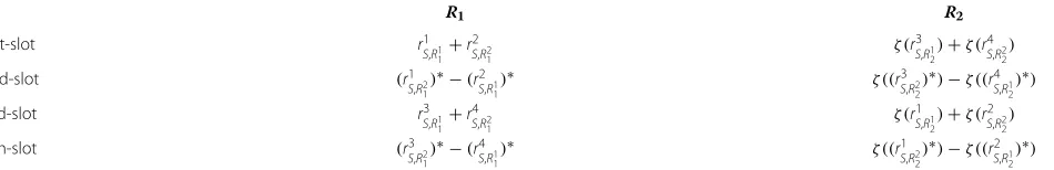
transmitted. The proceed mixed signals as Table 2, where ζ(.)represents the time-removal operation.
At the destination node D, after CP removal, the received signals for four successive OFDM symbols dura-tion can be written as
z1=
P2
2P1+1
(r1 S,R1
1+r
2 S,R2
1)hR1,D
+ζ(r3 S,R12 +r
4
S,R22)hR2,D
+w1,
(3)
z2=
P2
2P1+1
r1 S,R2
1
∗
−r2 S,R1
1
∗
hR1,D (4)
+ζr3 S,R2
2
∗
−r4 S,R1
2
∗
hR2,D
+w2, (5)
z3=
P2
2P1+1
r3 S,R1
1 +r
4 S,R2
1
hR1,D
+ζr1 S,R12 +r
2 S,R22
hR2,D
+w3, (6)
z4=
P2
2P1+1
r3 S,R21
∗
−r4 S,R1
1
∗
hR1,D
+ζr1 S,R2
2
∗
−r2 S,R1
2
∗
hR2,D
+w4, (7)
wherewi(i=1, 2, 3, 4)is also the AWGN with zero-mean and unit-variance from the relay node to the destination nodeDat theith time slot.
Then, the received signals atDare fed toN-point FFT and IFFT operation, respectively, since the length of CP is long enough. Following the propertyFFT(ζ(FFT(Xk)))= IFFT(FFT(Xk))[12], we can get the separating received signals as follows:
Z1
1=ρIFFT((r1S,R1 1+r
2 S,R2
1)hR1,D)+IFFT(w
1 1),
Z2
1=ρFFT(ζ(r3S,R1 2+r
4 S,R2
2)hR2,D)+FFT(w
2 1),
Z1
2=ρIFFT(((rS1,R2 1)
∗−(r2 S,R1
1)
∗)h
R1,D)+IFFT(w12), Z2
2=ρFFT(ζ((r3S,R2 2)
∗−(r4 S,R1
2)
∗)h
R2,D)+FFT(w22), Z1
3=ρIFFT((r3S,R1 1+r
4
S,R21)hR1,D)+IFFT(w
1 3),
Z2
3=ρFFT(ζ(r1S,R1 2+r
2
S,R22)hR2,D)+FFT(w
2 3),
Table 1 The received signals
r1
S,R1
1 −(
r2
S,R1 1)
∗ r3
S,R1
1 −(
r4
S,R1 1)
∗
r2
S,R2
1 (
r1
S,R2 1)
∗ r4
S,R2
1 (
r3
S,R2 1)
∗
r3
S,R1
2 −(
r4
S,R1 2)
∗ r1
S,R1
2 −(
r2
S,R1 2)
∗
rS4,R2
2 (
rS3,R2 2)
∗ r2
S,R2
2 (
r1S,R2 2)
∗
Table 2 The proceed mixed signals
R1 R2
1st-slot r1
S,R1 1+
r2
S,R2
1 ζ(
r3
S,R1 2)+ζ(
r4
S,R2 2)
2nd-slot (r1
S,R2 1)
∗−(r2
S,R1 1)
∗ ζ((r3
S,R2 2)
∗)−ζ((r4
S,R1 2)
∗)
3rd-slot r3
S,R1 1+
r4
S,R2
1 ζ(
r1
S,R1 2)+ζ(
r2
S,R2 2)
4th-slot (r3
S,R2 1)
∗−(r4
S,R1 1)
∗ ζ((r1
S,R2 2)
∗)−ζ((r2
S,R1 2)
Z1
4=ρIFFT((r3S,R2 1)
∗!−(r4 S,R11)
∗)h
R1,D)+IFFT(w14), Z2
4=ρFFT(ζ((rS1,R2 2)
∗−(r2 S,R1
2)
∗)h
R2,D)+FFT(w24),
(8)
wherewjk(j=1, 2)is the component ofwk.
After getting the separated signals, the scheme performs the addition and subtraction operations between two cor-relative separated signalsZ1kandZk2, respectively. The two new received signals are denoted as
Yk,1 = Zk1+Zk2,
Yk,2 = Zk1−Zk2, (9)
It means that two new received signals are obtained at each time interval. Finally, we can get an
Y= βSH+n, (10)
where the scalarβ=
P1P2
2P1+1,Yis a 8×1 vector consisted
of received signals, and
H = hS,R1
1hR1,D hS,R21hR1,D hS,R12hR2,D hS,R22hR2,D
T ,
andSandnare the equivalent 8×4 transmission matrix and 8×1 noise vector, respectively.
We next analyze the orthogonality of the transmission matrixS. We have
S = ⎡ ⎢ ⎢ ⎢ ⎢ ⎢ ⎢ ⎢ ⎢ ⎣
X1 −X2∗ −X3∗ X4 X1 −X2∗ −X3∗ X4
X2 X1∗ −X4∗ −X3 X2 X1∗ −X4∗ −X3
X3 −X4∗ X1∗ −X2 −X3 X4∗ −X1∗ X2
X4 X3∗ X2∗ X1 −X4 −X3∗ −X2∗ −X1 ⎤ ⎥ ⎥ ⎥ ⎥ ⎥ ⎥ ⎥ ⎥ ⎦ T
Obviously, we can rewriteS=[QJ QJ]T, whereQJis the Jafarkhani’s transmission matrix [3], andQJ is the trans-formation matrix of QJ, and QJ = QJ, where = diag[ 1, 1,−1,−1] is a diagonal matrix. Also, we have
QH J QJ =
⎡ ⎢ ⎢ ⎢ ⎢ ⎢ ⎢ ⎢ ⎢ ⎣
α 0 0 βJ
0 α −βJ 0
0 −βJ α 0
βJ 0 0 α
⎤ ⎥ ⎥ ⎥ ⎥ ⎥ ⎥ ⎥ ⎥ ⎦ , (11) and
QHJ QJ =QHJ QJ= ⎡ ⎢ ⎢ ⎢ ⎢ ⎢ ⎢ ⎢ ⎢ ⎣
α 0 0 −βJ
0 α βJ 0
0 βJ α 0
−βJ 0 0 α
⎤ ⎥ ⎥ ⎥ ⎥ ⎥ ⎥ ⎥ ⎥ ⎦ , (12)
whereα=4i=1|Xi|2andβJ =(X1X4∗+X1∗X4)−(X2X3∗+ X∗
2X3).
So the character matrix ofScan be written as
SHS= ⎡ ⎢ ⎢ ⎢ ⎢ ⎢ ⎢ ⎢ ⎢ ⎣
2α 0 0 0
0 2α 0 0
0 0 2α 0
0 0 0 2α
⎤ ⎥ ⎥ ⎥ ⎥ ⎥ ⎥ ⎥ ⎥ ⎦ . (13)
From (13), we know that the equivalent transmis-sion code S is a new kind of half rate O-STBC, it can achieve full diversity four. And comparing with the origi-nal Jafarkhani code, the coding gain is also increased.
In this proposed scheme, we can apply the Jafarkhani code to achieve full rate code at the transmitter, and full diversity at the receiver. The fast linear decoding algo-rithm [2] can be used, where we can omit the superscript of matrix elements for simplicity, as following.
Let ∈t denotes the permutations of the symbols from the first row to the tth row of the transmission matrix. The column position ofXiin thetth row is represented by ∈t (i) and the sign of Xi in the tth row is denoted by sgnt(i). Based on the orthogonality of the equivalent orthogonal code matrixS, the decision statisticsXiof the transmitted signalXican be constructed as
Xi= t∈η(i)
sgnt(i)·yt·h∗∈t(i), (14)
where η(i) is the set of rows of the transmission matrix includingxi,
˜ yt(i)=
⎧ ⎨ ⎩
yt, Xibelongs to thetth row ofS;
(yt)∗, Xi∗belongs to thetth row ofS,
h∗ ∈t(i)=
⎧ ⎨ ⎩
h∗
∈t(i), Xibelongs to thetth row ofS;
h∈t(i), Xi∗belongs to thetth row ofS.
Since the value ofXi only depends on the code symbol
Xi, the given received signals, the path coefficients and the structure of the transmission matrix are minimizing each individual decision metric as
Xi−Xi2+ ⎛ ⎝2
4
j=1
|hj|2−1 ⎞
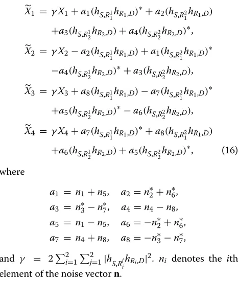
Applying (14), we obtain the following decision statistics:
X1 = γX1+a1(hS,R1 1hR1,D)
∗+a
2(hS,R2 1hR1,D)
+a3(hS,R1
2hR2,D)+a4(hS,R22hR2,D)
∗,
X2 = γX2−a2(hS,R1
1hR1,D)+a1(hS,R21hR1,D)
∗
−a4(hS,R12hR2,D)
∗+a
3(hS,R22hR2,D),
X3 = γX3+a8(hS,R1
1hR1,D)−a7(hS,R21hR1,D)
∗
+a5(hS,R1 2hR2,D)
∗−a
6(hS,R2 2hR2,D),
X4 = γX4+a7(hS,R1 1hR1,D)
∗+a
8(hS,R2 1hR1,D)
+a6(hS,R1
2hR2,D)+a5(hS,R22hR2,D)
∗, (16)
where
a1 = n1+n5, a2=n∗2+n∗6, a3 = n∗3−n∗7, a4=n4−n8, a5 = n1−n5, a6= −n∗2+n∗6, a7 = n4+n8, a8= −n∗3−n∗7,
and γ = 22i=12j=1|hS,Rj ihRi,D|
2. n
i denotes the ith element of the noise vectorn.
The whole scheme can achieve the full rate and the full diversity at the process of transmission and the receiver, respectively. Evidently the decoding complexity is reduced and the performance is improved, though the complex-ity of the receiver is increased. Also, we know that the proposed distributed network scheme has a higher cod-ing gain than conventional QO-STBC. Furthermore, this scheme can be achieved by using the TBH code.
Simulation results
In this section, we show the simulation performance of the proposed distributed STBC network scheme for the radiation-power-limited communication system. In our simulation, we considered the assumption of frequency selective Rayleigh flat fading channels by employing the ML-based decoding algorithm, and we select only one block-code to compare the performance with conven-tional distributed STBCs.
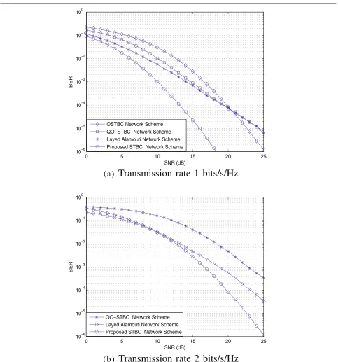
In this article, it is obvious that the rate of the system equals to the half of the rate of the multiple-antenna sys-tem (RMA) due to the two-hop channel model selected. Figure 2 shows the simulations, in which we choose the proposed distributed STBC network scheme with RMA 1, the conventional distributed QO-STBC scheme [3,10] with RMA 1, the distributed O-STBC network scheme [2] with RMA 12 and the Alamouti-base OFDM network scheme [11] with RMA 1 to compare the performance. As we known, the diversity order of the Alamouti-base OFDM network scheme is two, for the sake of fairness, we
select two-block layered Alamouti network scheme, the transmission matrix can be written as
SL =
x1 −x∗2 x3 −x∗4 x2 x∗1 x4 x∗3
T
. (17)
So the RMA of the layered Alamouti scheme comes to 2. And for each block-code, the diversity gain of the proposed distributed STBC network scheme, the con-ventional distributed QO-STBC scheme, the distributed O-STBC network scheme and the Alamouti-base OFDM network schemes are 4,<4, 4, and 2, respectively.
Figure 2a shows the simulations, in which we compared the performance of our proposed distributed STBC net-work scheme (QPSK) with the layered Alamouti netnet-work scheme (BPSK), the conventional distributed QO-STBC scheme (QPSK) and the distributed O-STBC network scheme (16QAM) for the transmission of 1 bits/s/Hz. And in Figure 2b, we show the performance of three schemes for the transmission of 2 bits/s/Hz.
From the simulation results, in Figure 2a, we can see that the proposed distributed STBC network scheme can achieve the full diversity, and the coding gain also increased. Simulation results show that the conventional distributed QO-STBC network scheme has better perfor-mance than the distributed O-STBC network scheme for the 1 bits/s/Hz transmission at low SNR, and it starts to deteriorate due to diversity loss when the SNR value exceeds 22 dB. The proposed network scheme outperform the layered Alamouti network scheme and the conven-tional QO-STBC network scheme about 4 and 5 dB at 10−3 BER due to the increase of diversity gain and cod-ing gain. The performance of the proposed distributed STBC network scheme outperform the conventional QO-STBC network scheme about 7 dB at 10−3 BER due to the increase of rate. Also, we select three model, the con-ventional distributed QO-STBC scheme (16QAM), the proposed distributed STBC network scheme (16QAM) and the layered Alamouti network scheme (QPSK), and do the simulations for the transmission of 2 bits/s/Hz in Figure 2b. It is clear that the proposed network scheme has the best performance. The analysis fits well in with simulation results.
Conclusions
0 5 10 15 20 25 10−6
10−5 10−4 10−3 10−2 10−1 100
SNR (dB)
BER
OSTBC Network Scheme QO−STBC Network Scheme Layed Alamouti Network Scheme Proposed STBC Network Scheme
(a)
Transmission rate 1 bits/s/Hz
0 5 10 15 20 25
10−6 10−5 10−4 10−3 10−2 10−1 100
SNR (dB)
BER
QO−STBC Network Scheme Layed Alamouti Network Scheme Proposed STBC Network Scheme
(b )
Transmission rate 2 bits/s/Hz
Figure 2Performance of the proposed DSTBC network scheme with frequency selective rayleigh flat fading channel.(a)Transmission rate 1 bits/s/Hz.(b)Transmission rate 2 bits/s/Hz..
with a simply operation and forwarded to the destination node.
During the whole processing, the equivalent QO-STBC with the full rate is implementing, and we received an equivalent half diversity orthogonal transmission code at the receiver through signals separated and re-constructed.
remarkable improvement due to the increase of coding gain and diversity gain. Also, it has new approach for the design of the future distributed STBC network scheme.
Competing interests
The authors declare that they have no competing interests.
Acknowledgements
This work was supported by the World Class University (WCU) R32-2012-000-20014-0, BSRP2010-0020942, MEST 2012-002521, NRF, Korea, and the Natural Science Foundation of Liaoning Province (No. 201102076), China.
Author details
1College of Information Technology, Eastern liaoning university, Dandong,
118003, P. R. China.2College of Foreign Language, Eastern liaoning university, Dandong, 118003, P. R. China.3Institute of Information and Communication, Chonbuk National University, 664-14 Deokjin-dong, Jeonju 561-756, Republic of Korea.
Received: 4 January 2012 Accepted: 17 July 2012 Published: 17 July 2012
References
1. A Alamouti, A simple transmit diversity scheme for wireless communications. IEEE J. Sel. Areas Commun.16, 1451–1458 (1998) 2. V Tarokh, H Jafarkhani, AR Calderbank, Space-time block codes from
orthogonal designs. IEEE Trans. Inf. Theory.45, 1456–1467 (1999) 3. H Jafarkhani, A quasiorthogonal space time block encodes. IEEE Trans.
Commun.49, 1–4 (2001)
4. O Tirkkonen, A Boariu, A Hottinen, Minimal nonorthogonality rate 1 space-time block code for3+Tx antennas. inProc. IEEE 6th Int. Symp. Spread-Spectrum Techniques and Applications (ISSSTA 2000), Volume 2. (Parsippany, New Jersey, USA, 429–432, 2000)
5. X W Su, Xia, Signal constellations for quasi-orthogonal space-time block codes with full diversit. IEEE Trans. Inf. Theory.50, 2331–2347 (2004) 6. JN Laneman, DNC Tse, GW Wornell, Cooperative diversity in wireless
networks: Efficient protocols and outage behavior. IEEE Trans. Inf. Theory (in press).50, 3062–3080
7. JN Laneman, GW Wornell, Distributed Space-Time Coded Protocols for Exploiting Cooperative Diversity in Wireless Networks. IEEE Trans. Inf. Theory.59(10), 2415–2525 (2003)
8. A Sendonaris, E Erkip, B Aazhang, User cooperation diversity. Part I: System description. IEEE Trans. Commun.51, 1927–1938 (2003) 9. A Sendonaris, E Erkip, B Aazhang, User cooperation diversity. Part II:
implementation aspects and performance analysis. IEEE Trans. Commun. 51, 1939–1948 (2003)
10. Y Jing, B Hassibi, Distributed space-time coding in wireless relay networks. IEEE Trans. Wirel. Commun.5(12), 3524–3536 (2006)
11. Z Li, X-G Xia, B Li, Achieving full diversity and fast ML decoding via simple analog network coding for asynchronous two-way relay networks. IEEE Trans. Commun.57(12), 3672–3681 (2009)
12. JG Proakis, DG Manolakis,Digital Signal Processing: Principles, Algorithms and Applications. 3rd edn. (New Delhi: Prentice-Hall, 1996)
doi:10.1186/1687-6180-2012-147
Cite this article as:Songet al.:A simple asynchronous distributed STBC
network scheme with full diversity.EURASIP Journal on Advances in Signal
Processing20122012:147.
Submit your manuscript to a
journal and benefi t from:
7Convenient online submission 7Rigorous peer review
7Immediate publication on acceptance 7Open access: articles freely available online 7High visibility within the fi eld
7Retaining the copyright to your article