Optimal Design of Pi Controller for Doubly Fed Induction
Generator
B.Sowjanya Kalyani , A.V.S.Lakshmi ,
P.Jagruthi ,
D.V.S.J.Poojitha
Assistant Professor,EEE Department,Dadi Institute of Engineering and TechnologyAndhra Pradesh, India Abstract:
Due to continuous increase in power demand we can not depend on limited conventional sources so we go for the renewable energysources in which wind energy has proven technology. Among the different variable speed wind turbine doubly fed induction generator(DFIG) is the commonly used wind turbine in growing wind market. DFIG is usually used to satisfy grid code requirements such as power quality improvement, grid stability,grid synchronization, power control andfault ride through in grid connected wind energy conversion system. To fulfill these requirements DFIG needs a control strategy for both stator and rotor side along with variable frequency power electronic converters (VFC).
VFC normally controlled by set of PI controllers, tuning of these controller gains is a tedious task due to non-linearity and complexity of the system. PSO algorithm is used to to find the optimal parameters of various PI controllers for rotor side converter of VFC to apply a proper voltages to the rotor windings to maintain constant terminal voltage and control of active and reactive power of DFIG.
Key words – Doubly fed induction generator. Particle Swarm Optimization. Tuning of PI controllers. Controlling of DFIG
Introduction:
Due to continous mismatch between load demand, depleting fossil fuels, environmental concerns forced the power sector to move towards alternative power generation sources apart from the conventional sources. Because of this situation renewable energy sources became the hot research spot in the recent past.Among the various renewable energy sources wind is one of the mostly available source and has many prominent advantages compared with others. There are more number of choices of topologies available to design a wind turbines. Out of all,
horizontal axis,three-bladed,up wind turbines are most commonly used.Variable speed wind turbines are used for larger machines,whereas fixed speed wind turbines for smaller machines.For fixed speed wind turbines the changein wind speed effects the power quality of the grid. In variable speed wind turbines the generator output power at variable wind speed is controlled by using power electronic equipment. Hence power quality impact caused by wind turbine can be improved compared to a fixed speed wind turbine. During the last decade, the variable speed wind turbine (VSWT) along with doubly fed induction generator (DFIG) is more
advantageous compare to other
topologies.InDFIGstator is directly connect to grid and rotor is connected to grid through partial-load (25-30%) variable frequency AC/DC/AC converter (VFC) and transformer. VSWT along with the
synchronous generator (SG) uses
fullscalerated(100%) AC/DC/AC converters (VFC) placed in between stator and grid therefore compare to SG, VFC of DFIG is smaller and cheaper.
based on the step response. Wei Qiao et.al. suggested [4] that Particle Swarm Optimization (PSO) used for single and multi objective non linear optimization, in this PSO algorithm is used to find the optimalparameters of the various PI controllers for the RSC of VFC and he defined the new time domain fitness function to measure the performance of the controllers and improved the transient performance of the WTGS. Joao P.A. Vieira used [3] GA to determine the optimal gains for the PI controller in RSC of DFIG to reduce over current in the rotor circuit and compares transient performances with formal methodology to design PI controller using poles placement.
Workingof doubly fed induction generator:
In DFIG the mechanical power at machine shaft is converted into electrical power which is supplied to the grid through both stator and rotor windings. DFIG operates similar to the synchronous generator but synchronous speed of DFIG can be varied by adjusting the frequency of AC currents fed into the rotor windings. The frequency of ac currents (𝑓𝑟𝑜𝑡𝑜𝑟)
that need to be fed into the DFIG rotor windings in order to match frequency of stator voltage and grid (𝑓𝑔𝑟𝑖𝑑) is given by the equation (1).
𝑓𝑟𝑜𝑡𝑜𝑟= 𝑓𝑔𝑟𝑖𝑑−
𝑛𝑟𝑜𝑡𝑜𝑟∗ 𝑁𝑝𝑜𝑙𝑒𝑠 120
Where, 𝑛𝑟𝑜𝑡𝑜𝑟= speed of rotor in rotations/min 𝑁𝑝𝑜𝑙𝑒𝑠= Number of poles in DFIG per phase.
Controlling of DFIG:
In DFIG configuration, wound rotor induction machine is used but both stator and rotor windings are connected to grid where stator winding is directly connected to the grid whereas rotor winding is connected through variable frequency converter(VFC) to the grid. By controlling VFC we can produce electrical power at a constant voltage and frequency over a wide range of speed from sub-synchronous to super sub-synchronous speed.
The converter near to rotor circuit is called as rotor side converter (RSC), whereas near to grid is called
Pm = Ps + Pr
Where, Pm is mechanical power, Ps is stator power, Pr(-S*PS) is rotor power and S is slip of the machine. In sub synchronous mode (S is positive) only stator produce active power, rotor takes the power from the grid. But in super synchronous mode (S is negative) both stator and rotor can produce active power. Whereas reactive power can be generated or absorbed based on control techniques being used and amount of reactive power is controlled by applying proper voltage magnitude to the rotor circuit.
VFC control includes control of RSC and GSC converter control,thedecoupled control of stator side active power (by speed control) and reactive powers (rotor current regulation) is done by RSC. For this the instantaneous three phase rotor current and its regulation is sampled and transformed into d-q components Id and Iq in the stator – flux oriented reference frame. The reference values of idrand iqrcan be determined directly from the Qs and Pscommands (these are functions of individual current components). The error signals are generated by comparing actual current signals with reference current signals by passed through PI controllers which are used to generate IGBT gate control signals to control the IGBT converter by PWM module. Irrespective of magnitude and direction of rotor power the dc link voltage is maintained constant by GSC, at any instant the power exported by GSC is determined by the state of DC link voltage, if the input and output power to the dc-link capacitor do not match then the dc-link voltage will change. GSC should maintain the voltage within the desired range when DFIG is in the weak power system and there is no reactive power compensation whereas in strong power system the reactive power needs to be set to zero by GSC.
Proposed methodology
This paper the parameters of PI controller are tuned using Particle swarm optimization with a objective toimprove the transient response of active and reactive power of DFIG to get a constant terminal voltage.
Objective function = min(variance(Ps))
Where Ps is the active power values of DFIG at each point instant of time.
Particle Swarm optimization
Particle swarm optimization is a biologically inspired a search algorithm which Particles search the search space for a optimal solution. These particles imitates the social behavior of birds and fish schooling in search of food. Each particle fly with a velocity and changes its position and update its velocity based onpersonal best and global best positions. In this paper particle swarm optimization has been used to tune The PI controller parameters.
Simulink Implementation of DFIG
Fig. 1 shows the Simulink diagram of DFIGPI. In this model rotor is excited by slip frequency of voltage derived from PI controller. These PI controllers are tuned using Particle swarm optimization technique. To improve transient response of active power and reactive power of DFIG
Fig .1 Simulation block diagram of DFIG
Fig.2 dynamic model of induction machine in arbitrary reference frame
Fig.3 Simulinkdiagram for Grid side converer
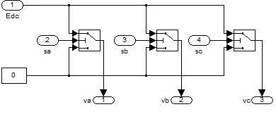
The grid side converter is modelled through the mathematical functions in ordered to get the actual function of inverter
Fig.4 Simulink diagram for rotor side converter
Wind turbine output power is controlled by rotor side converter. The power is controlled in order to follow a pre-defined Tracking characteristics.
Fig.5 Three phase stator voltage.
Fig.6 Three phase rotor voltage.
Fig.7 Stator active power.
Fig.8 Stator reactive power
Fig.9 Rotor active power
Fig.10 Rotor reactive power.
Conclusion
The results obtained by the proposed method shows its effectiveness in improving the transient response of active power and reactive power of DFIG consequently leads to get a constant terminal voltage of DFIG. Proposed method also ensures a independent control of active and reactive power of DFIG
References:
[1] R.G. Almeida, E.D. Castronuovo, J.A. Peças Lopes, "Optimum Generation Control in Wind Parks When Carrying Out System Operator Requests,"IEEE Transactions Power System. Vol. 19. pp1942-1950. 2006
[2] M.V.A. Nunes, H.H. Zurn, U.H. Bezerra, J.A. Peças Lopes, R.G.Almeida, "Influence of the Variable Speed Wind Generators in Transient Stability Margin of the Conventional Generators Integrated in Electrical Grids," IEEE Transactions on Energy Conversion. vol.19(4), pp.692-701. 2004.
[3]
João P. A. Vieira, Marcus N. A. Nunes, and
Ubiratan H. Bezerra, “Design of Optimal PI
Controllers for Doubly Fed Induction Generators
in Wind Turbines Using Genetic Algorithm”
IEEE 2008.
[4]
W. Qiao, G.K. Venayagamoorthy, R.G.
Harley, "Design of Optimal Control PI
Controllers for Doubly Fed Induction Generators
Driven by Wind Turbines Using Particle Swarm
Optimization," Int. Joint Conf. on Neural
Network, Vancouver, BC, Canada, pp.
1982-1987, July, 2006
[5] Y. Lei, A. mullane, G. Lightbody, R. Yacamini, "Modeling of the Wind Turbine With a Doubly Fed Induction Generator for Grid Integration Studies," IEEE Transactions on Energy Conversion. vol. 21, pp.257-264
during voltage dip,” IEEE Trans.Energy Conversion, vol. 20, no. 2, Jun. 2005, pp. 435-441.
[8] M. Lown, E. Swidenbank, B. W. Hogg, “Adaptive fuzzy logic control of a turbine generator system,” IEEE Trans. Energy Conversion, vol.12, no. 4, Dec. 1997, pp. 394-399.
[9] R. Pena, J. C. Clare, and G. M. Asher, “Doubly fed induction generator using back-to-back PWM converters and its application to variable-speed wind-energy generation,” IEE Proceedings – Electric Power Applications, vol. 143, no. 3, May 1996, pp. 231-241.