R E S E A R C H
Open Access
Vector perturbation based adaptive distributed
precoding scheme with limited feedback for
CoMP systems
Tiankui Zhang
1*, Xiaochen Shen
1, Laurie Cuthbert
2, Lin Xiao
3and Chunyan Feng
1Abstract
A downlink adaptive distributed precoding scheme is proposed for coordinated multi-point (CoMP) transmission systems. The serving base station (BS) obtains the optimal precoding vector via user feedback. Meanwhile, the precoding vector of each coordinated BS is determined by adaptive gradient iteration according to the perturbation vector and the adjustment factor based on the vector perturbation method. In each transmission frame, the CoMP user feeds the precoding matrix index back to the serving BS, and feeds back the adjustment factor index to the coordinated BSs, which can reduce the uplink feedback overhead. The selected adjustment factor for each coordinated BS is obtained via the precoding vector of the coordinated BS used in the previous frame and the preferred precoding vector of the serving BS in this frame. The proposed scheme takes advantage of the spatial non-correlation and temporal correlation of the distributed MIMO channel. The design of the adjustment factor set is given and the channel feedback delay is considered. The system performance of the proposed scheme is verified with and without feedback delay respectively and the system feedback overhead is analyzed. Simulation results show that the proposed scheme has a good trade-off between system performance and the system control information overhead on feedback.
Keywords:Coordinated multi-point, Distributed precoding, Limited feedback, Vector perturbation, Adjustment factor
I. Introduction
Coordinated multi-point (CoMP) transmission/reception is considered as one of the key potential technologies for LTE-Advanced [1]. CoMP transmission technology takes advantage of distributed multiple antennas with a non-correlated spatial channel to achieve spatial multiplexing gain or transmit diversity gain. The coordinated point can be a base station (BS), a remote radio unit (RRU), or a relay node (RN). In joint transmission CoMP, multiple points share the data for a simultaneous joint transmission to a user [1].
In the downlink multi-antenna systems, the precoding is mainly characterized into two classes: (i) precoding vector codebook based, in which the user estimates the downlink channel state information (CSI) and finds the best precoding vector in the codebook, then feeds back
the precoding matrix index (PMI) to the BS; (ii) non-codebook based, in which the BS calculates the preferred precoding vector according to the CSI fed back from the user. For both CSI or PMI, the feedback overhead scales with the number of cooperation cells in the CoMP sys-tem. There is, therefore, a need for an effective precoding scheme that can obtain the diversity gain with a limited uplink feedback overhead.
There are two main precoding schemes for CoMP sys-tems with joint transmission proposed within 3GPP: (i) weighted local precoding (WLP) [2]; (ii) multicast/broad-cast over single frequency network (MBSFN) [3]. In WLP, each BS uses a different precoding vector with additional phase factors for coherent combining of beams from dif-ferent cells. The user obtains the signal using a coherent receiver to improve the received signal to noise ratio (SNR) of users. WLP needs to feed back the PMI and the phase factor to each BS, so it has a high feedback over-head. In MBSFN, all the BSs employ the same precoding * Correspondence: [email protected]
1Beijing University of Posts and Telecommunications, Beijing, China
Full list of author information is available at the end of the article
vector to the user, so it only needs one PMI fed back to all the BSs. MBSFN needs a small amount of feedback, but the received SNR of users is poor, because the downlink signal from the BSs may interfere with each other and the users can only receive the signal through a broadcast reception mode.
In fact, the distributed beamforming scheme of the multi-antenna systems with limited feedback had drawn much attention in wireless sensor networks [4-7] and relay cooperation networks [8-10]. In this literature, vector per-turbation is a popular and efficient technique for distribu-ted beamforming scheme to mitigate the requirement on CSI feedback [4-7,9]. For feedback overhead reduction, vector perturbation based adaptive precoding schemes are designed by perturbing the precoding/beamforming vectors [4-7,9,11-15].
A method for applying overlaid perturbation vectors for gradient-feedback transmit antennas array adaptation for CDMA networks was proposed in [11]. The transmitter can adjust the antennas from the current vector in the positive direction or negative direction by using a pertur-bation vector to form an odd weighted vector or an even weighted vector. The pilot was sent using these two vec-tors alternately, and the receivers fed back the preferred vector according to the signal strength decision with one bit; the transmitter updates the two weighted vectors according to the feedback. The vector perturbation based antenna-adaption method has been extended to multi-user systems [12,13]. A beamforming scheme of OFDM based on vector perturbation was given to reduce the sys-tem feedback in [14], which was different from the method in [11] in terms of the generation of the perturbation vec-tor. The perturbation vector in [11] was generated ran-domly, while in [14] the initial perturbation vector was selected from a Householder codebook, and the perturba-tion vector in each transmission was generated by the quasi-Monte Carlo method.
References [4-7,9] also used the perturbation idea to reduce the CSI feedback of distributed antennas systems in a similar fashion. In [4-7], feedback-assisted distribu-ted beamforming with phase perturbation in wireless sensor networks was considered: each transmitter adjusted its phase randomly at each iteration and the receiver broadcasted one bit of feedback per iteration indicating whether its net SNR was better or worse than before. If it was better, all transmitters kept their latest phase perturbations; otherwise they all undid the phase perturbation. [9] introduced the perturbation idea into relay networks with half-duplex amplify-and-forward relays.
The perturbation vector used to perturb the precoding vector or phase can be stochastic (random selected) [4-7,11-13], deterministic (predefined in the perturbation
vector set) [9,14], and hybrid [15]. Perturbation based on a deterministic perturbation vector set can avoid exten-sive signaling and feedback overhead [9].
This article proposes a vector perturbation-based adaptive distributed precoding (ADP) scheme for down-link CoMP joint processing which serves the user by one serving BS and several coordinated BSs. The pro-posed ADP can achieve better system performance than MBSFN and it will reduce the feedback overhead com-pared with WLP.
The precoding vector for the serving BS is given as fol-lows. Both the user and the serving BS have knowledge of the precoding vector set (called precoding codebook in CoMP systems). The user feeds the PMI back to the ser-ving BS according to the local CSI from the serser-ving BS to the user.
The precoding vector for each coordinated BS is given as follows. Both the user and the coordinated BSs have knowledge of the perturbation vector set and the adjust-ment factor set. It should be noted that the perturbation vector set is deterministic and in each frame the perturba-tion vector is picked up in a cyclic fashion [9] with a pre-defined order known to the users and to the BSs. In each frame, the user calculates the received SNR according to the perturbation vector used in this frame and the precod-ing vector used in the pre-frame, and an adjustment factor of each coordinated BS is selected as the optimal adjust-ment factor if it can give the maximum received SNR of this user. Then the user only feeds back the index of the adjustment factor to each coordinated BS, which needs fewer feedback bits than PMI feedback. After receiving the adjustment factor index feedback, each coordinated BS updates the precoding vector using adjustment factor and the perturbation vector via adaptive gradient iteration method.
Contributions of this article are: (1) The ADP gives the optimal precoding vector of the serving BS and uses gra-dient adaption for coordinated BSs precoding; the pre-coding vectors of the coordinated BSs are also in phase synchronization with the serving BS. So ADP can be seen as a tradeoff between optimal precoding feedback from WLP and gradient adaption iteration. (2) The ADP uses the deterministic perturbation vector sets and lets both the BSs and the user have this knowledge, so the user can make the decision without any additional pilot. (3) More than one adjustment factor is used in the ADP to adjust the perturbation vector, which gives a better approxima-tion to the optimal precoding as the channel state varies.
II. System model of CoMP joint processing
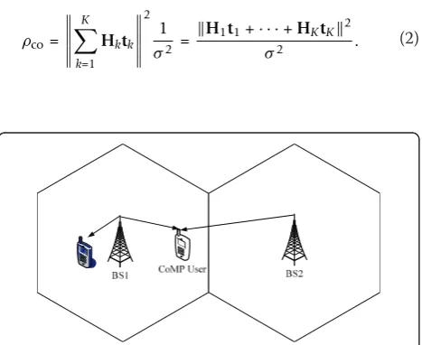
A multi-cell orthogonal frequency division multiplexing access (OFDMA) cellular system is considered and CoMP is used to improve the system performance. Figure 1 illus-trates the downlink joint processing transmission of BS cooperation. The users in each cell are divided into cell-central users and cell-edge users according to the large scale channel fading. The cell-edge users are defined as CoMP users that are served by the joint processing trans-mission. The proportional scheduling algorithm is used for multiple CoMP users. Assuming that the number of cooperation BSs transmitting to one CoMP user isK, the BS covering this user is the serving BS of this user, and the otherK -1 BSs are the coordinated BSs of this user.
Single layer transmission is used in the CoMP, so we only focus on the spatial diversity gain here to increase the cell-edge user throughput. The CoMP user has the CSI of all the BSs and the BSs do not have such infor-mation. The number of transmission antennas on each BS isM, and the number of user receiving antennas is
N. Hk Î CN×Mdenotes the downlink channel matrix
from thekth BS to the CoMP user. The downlink signal isx, and the precoding vector of thekthBS is tk = [tk1,
tk2, ...,tkM]Twith a power constraint║tk║= 1.
The received signal of the user is
y=
K
k=1
Hktkx+n, (1)
in which n, is a zero-mean complex additive white Gaussian noise vector with variances2.Hltlis the chan-nel matrix of the serving BS multiplied by its precoding vector andHktk(k≠1) is the channel matrix ofkth
coor-dinated BS multiplying its precoding vector. The received SNR of the CoMP user is
ρco=
K
k=1 Hktk
2
1
σ2 =
H1t1+· · ·+HKtK2
σ2 . (2)
III. The principle of ADP
A. Optimal distributed precoding of CoMP
In (2), letHktk=Akgk; Ak= diag(akl, ..., akN), which is
anN-dimensional diagonal matrix, denoting the ampli-tude-frequency characteristic of Hktk; and the
phase-fre-quency characteristic ofHktk isgk = [ejjkl...ejjkN]T. So
(2) can be rewritten as
ρco=
A1g1+· · ·+AKgK
2
σ2 . (3)
With the power constraint of each BS, ifgl= ··· = gk,
maximization ofrcowill be achieved. Set the phase vec-tor of the serving BSg1 to be the basic phase vector, the
kth coordinated BS adjusts its phase vector gk to be
equal to thegl, i.e., letgk=gl, which equals maximizing
║Algl+Akgk║2, so maximizing rcois replaced by
maxi-mizing the SNR of thekthcoordinated BS and the ser-ving BSrk, expressed as
ρk=
H1t1+Hktk2
σ2 , k= 2,. . .,K. (4)
Each coordinated BS gets the optimal distributed pre-coding vectortkaccording to (4). As a result,
maximiza-tion (2) can be achieved, so this is an optimal distributed precoding method.
B. Adaptive gradient iteration
From (4) it can be seen that, in order to maximize rk,
the precoding vectortkof the kth coordinated BS should
satisfy the following function,
max
tk
H1t1+Hktk2,k= 2,. . .,K
s.t. |tk|2=1
. (5)
Set Jk=║Hltl+Hktk║2 = (Hltl+Hktk)H (Hltl+Hktk).
The first-order optimal condition of maximization (4) is the gradient ofJkin terms of tk is zero. The gradient of
Jk in terms of tk is calculated as
∇(Jk)= 2
HHkH1t1+HHkHktk
.
The perturbation vector of the kthcoordinated BS is defined as wk and the adjustment factor is b, so the
positive direction and negative direction adjusting of the precoding vector is
tke=tk+βwk
tko=tk−βwk. (6)
The received signal power difference between the positive direction and negative direction adjustment is
q=H1t1+Hktke2− H1t1+Hktko2. (7)
Taking (6) into (7), we have
The received signal power of the adjusted precoding vector from (6) is always on the gradient curve of Jk, so
any gradient iteration based on (6) can maximize (5).
IV. The design of ADP
Definition: the adjustment factor bi, i = 1, ..., L is
selected from the adjustment factor set B = {b1,b2, ..., bL}; the perturbation vector of thekth (k≠ 1)
coordi-nated BS in the nthtransmission frame is wnk, which is selected from the perturbation vector set w = {w1, w2, ...,wF}.
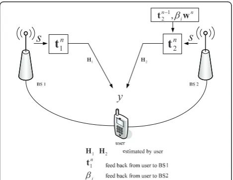
The proposed ADP scheme is based on the assump-tion that both the BSs and the users have knowledge of the precoding codebook, the adjustment factor set and the perturbation vector set. Both the user and all the coordinated BSs use the perturbation vector in the same predefined order in each frame.
Based on the optimal distributed precoding and the gradient iteration of the perturbation vector, the idea of ADP is that in each downlink transmission frame, the user selects and feeds the best PMI to the serving BS according to the channel state H1, and the user selects and feeds the best adjustment factorbito thekth
coordi-nated BS. Thekth coordinated BS will calculate the pre-codingtnkaccording to thebi,wnkandtnk−1, that is
A. Procedure of the ADP scheme
The initial precoding vector of each BS is given by PMI feedback, but after the first frame, only the precoding vector of the serving BS is given by PMI feedback, and the coordinated BS only needs the adjustment factor index feedback. The procedure of the ADP scheme is given as follows:
Step 1: in thenthframe, the user selects a best precod-ing vector for the servprecod-ing BS from the precodprecod-ing code-book to maximize the serving BS SNR r1=║H1t1║2/s2. If the size of the codebook is 2C, the selected PMI infor-mation can be fed back to the serving BS with C bits.
Step 2: in thenth frame, for thekth(k≠1) coordinated BS, the user picks a perturbation vector wnkfrom the perturbation vector set. Then thiswnkis weighted by dif-ferent adjustment factorbiin the adjustment factor set.
The user will calculate the precodingtnk according to (9)
and the received SNRrk according to (4). The user will
choose the adjustment factorbi which can achieve the
optimaltnkto maximizerk. The selected adjustment
fac-torbi will be fed back to thekth coordinated BS with
⌈log2L⌉bits.
Step 3: after receiving the adjustment factor index feedback, each coordinated BS updates the precoding vectortnkbased on the precoding vector tnk−1used in the previous frame according to (9), which is a function of the adjustment factorbiand the perturbation vectorwnk.
Step 4: the serving BS and the coordinated BSs trans-mit the data to the user jointly.
This scheme is given in Figure 2.
The perturbation vector set used in this article is gen-erated based on the Lloyd algorithm [16]. This is an off-line method and the perturbation vector set is predefined, so it does not increase the complexity of the system. It should point that the perturbation vector set used in the proposed ADP scheme can also be designed by other methods. The precoding codebook also can be used as the perturbation vector set, which will reduce the memory space both in the BS and in the user.
B. Design of the adjustment factor set
The adjustment factor is very important for such a vec-tor perturbation based adaptive distributed precoding scheme. The selected adjustment factor for the coordi-nated BSs should generate a better adaptive precoding vector to approximate the optimal precoding vector obtained from the local channel state. If the value of bi
is large, the change from the precoding vectortnkto tnk−1
may be very large which will cause an over-adjustment problem. Otherwise, the change may be too small to fol-low the channel state variation. This section gives the
method for designing the adjustment factor set, which is obtained from offline statistics by Monte Carlo.
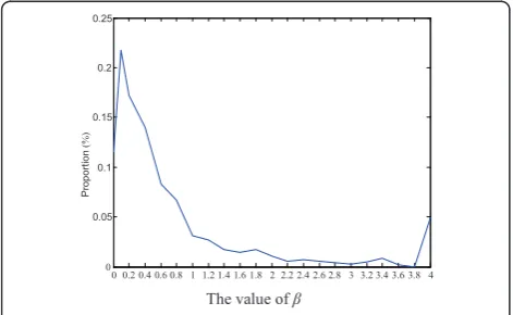
Many initial adjustment factors are used in the Monte Carlo simulation, and the adjustment factors that have been used frequently are picked out to form the adjust-ment factor set. The optimal value of b is tracked by simulation without considering the feedback overhead. The set of b is from 0 to 4 with step 0.2, i.e., B= [0: 0.2: 4]. In each transmission frame, the adjustment fac-tors of the coordinated BSs are selected from this set as the optimal value of b. The statistics of the optimal value ofbare given in Figure 3.
The horizontal axis is the value ofb, and the vertical axis represents the proportion of that value ofb being selected. It should be pointed out that the proportion at b= 4 also contains those values of b> 4 that have been selected. The statistics results show that, when b> 1, the proportion of theb being selected is very low and becomes a steady state, especially when b > 2; while, when b < 1, the proportion of the bbeing selected is very high. Based on the results, two values ofb will be picked to present the statistical average values, one is selected from b< 1 and another one is selected from b> 1.
The statistical average value ofbis
ˆ
in whichNis the number ofbi used in the statistics,
and pi is the proportion of the bi to be selected. The
two statistical average values of bare obtained from 0 <b < 1 and 1 <b< 4 respectively: βˆ1= 0.2andβˆ2= 2.
Since the adjusting of the perturbation vector has both a positive direction and negative direction, the adjustment factor set is defined asB= {-2,-0.2,0.2,2} finally.
The simulation results of the effect of the adjustment factor set given in Section V also provide the verification of the design of the adjustment factor set.
C. Analysis on channel delay
In each frame, the channel state is obtained by channel measure and estimated. However, in practical systems, the feedback delay means that the channel state informa-tion used for transmission cannot match the real channel state, which leads to poorer system performance. If the precoding vector and the adjustment factor can be selected based on a predicted channel state information feedback, the performance loss can be compensated. In the following analysis, the adjustment factor design based on channel state prediction is considered.
The channel state prediction can be achieved based on the temporal correlation of the distributed MIMO chan-nel. Considering the system has a feedback delayTc, and
the channel response att1isHt1, the channel response at
t1+TCisHt1+TC. The method for adjustment factor is as
follows.
The channel response of each antenna is
h∼CN0,σh2independent and identically distributed zero-mean Gaussian distribution, which is a Rayleigh channel with a maximum Doppler shift fd. We have
EHt1+TcHt1H
=ρσh2IMandr=JO(2πfdTc) is the
cor-relation factor. So the statistically estimated value of
Ht1+TC based on the measured value of Ht1 is EHt1+Tc|Ht1 =ρHt1
k. TakingHt1+TC and (9) into (2) will give an adjustment factor to maximize (2).
For the Rice MIMO channel, the channel matrix is
H= line of sight component and the Rayleigh fading compo-nent of the channel matrixH, respectively.HRay is the Rayleigh distribution and presented by Kronecker as
HRay=Hw
Rt, (12)
in which, Hw is the decorrelating channel matrix,
Rt=E
HHwHw . So the mean and correlation matrix of the Rice channel matrix can be expressed as
E{H}=
Using the same method as for the Rayleigh channel, an adjustment factor can be obtained to maximize (2) when the statistic estimated value of mean and 0 0.2 0.4 0.6 0.8 1 1.2 1.4 1.6 1.8 2 2.2 2.4 2.6 2.8 3 3.2 3.4 3.6 3.8 4
correlation matrix of the Rice channel matrix are known by the receiver side in the BS.
V. Simulation results
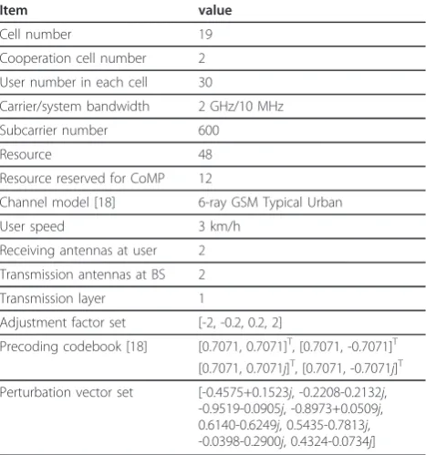
The downlink FDD CoMP system is considered for simulation. In FDD systems, the system control informa-tion will be fed back with the uplink control channel, which will not affect the downlink throughput but will reduce the uplink net throughput if the control informa-tion overhead is large. In the simulainforma-tion, the downlink throughput and the feedback overhead of the proposed ADP scheme are given and compared with that of MBSFN and WLP. The number of cooperation cells is two. CoMP users are those at the edge of the cell [17]. The simulation parameters are given in Table 1.
A. Simulation on adjustment factor
In Section IV, the adjustment factor set design is given, and the set is defined as B = {-2,-0.2,0.2,2}; here, we will give the simulation results of the system total through-put with different adjustment factor sets.
The system total throughput is defined as the sum average throughput of all the users in each cell, and the average throughput of each user is the ratio of the total transmission bits and transmission times, the unit is b/s. If there are two elements in the set, one statistical value is given in the positive direction of b. According to (10),βˆ≈0.67. The following three sets are compared by simulation, as shown in the Table 2.
If there are four elements in the set, two statistical aver-age values ofbare obtained by (10),βˆ1≈0.27when 0 <b < 1 andβˆ2≈2.19when 1 <b< 4. The following five sets are compared by simulation, as shown in Table 3.
From the simulation results in Tables 2 and 3, it can be seen that, the adjustment factor set [-2, -0.2, 0.2, 2] will achieve the largest total throughput of CoMP users among all the sets.
B. Simulation without feedback delay
In this section, the system performance is given under the assumption that the system control information (PMI and adjustment factor) can be fed back from the user to the BSs without delay. Table 4 shows the com-parison of the total throughput of CoMP users. Figure 4 is the comparison of cumulative distribution function (CDF) curve of the average throughput of CoMP users. From the simulation results, it can be seen that (i) the WLP and the ADP offer a significant improvement in system performance over MBSFN, and (ii) the WLP and the ADP have nearly the same system performance. The user throughput of ADP is the largest, 20% more than that of MBSFN, and 2% more than that of WLP.
With MBSFN, all the BSs send the data with the same precoding vectors without considering the channel state of different BSs, and the user cannot receive the data with coherent combination. ADP and WLP give the pre-coding vectors considering the local channel state of dif-ferent BSs and maximize the received SNR, and the user can receive the data with coherent combination.
C. Simulation with feedback delay
In this section, the feedback delay with 3 transmission time intervals (TTI) is considered, i.e., the system con-trol information feedback has 3 frames delay with the current channel state. Table 5 is the comparison of the Table 1 CoMP system simulation parameters
Item value
Cell number 19
Cooperation cell number 2
User number in each cell 30
Carrier/system bandwidth 2 GHz/10 MHz
Subcarrier number 600
Resource 48
Resource reserved for CoMP 12
Channel model [18] 6-ray GSM Typical Urban
User speed 3 km/h
Receiving antennas at user 2
Transmission antennas at BS 2
Transmission layer 1
Adjustment factor set [-2, -0.2, 0.2, 2]
Precoding codebook [18] [0.7071, 0.7071]T, [0.7071, -0.7071]T [0.7071, 0.7071j]T, [0.7071, -0.7071j]T
Perturbation vector set [-0.4575+0.1523j, -0.2208-0.2132j, -0.9519-0.0905j, -0.8973+0.0509j, 0.6140-0.6249j, 0.5435-0.7813j, -0.0398-0.2900j, 0.4324-0.0734j]
Table 2 Simulation results on different adjustment sets (TWO ELEMENTS)
Adjustment set Total throughput (Mb/s)
[-0.1, 0.1] 2.8605
[-0.6, 0.6] 3.1007
[-0.7, 0.7] 3.0725
Table 3 Simulation results on different adjustment sets (FOUR ELEMENTS)
Adjustment factor set Total throughput (Mb/s)
[-2, -0.1, 0.1, 2] 3.1665
[-2, -0.2, 0.2, 2] 3.2038
[-2, -0.3, 0.3, 2] 3.1603
[-2.1, -0.2, 0.2, 2.1] 3.1972
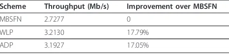
total throughput of CoMP users with 3 TTI feedback delay. Figure 5 shows the CDF curve of the CoMP user average throughput with 3 TTI feedback delay. As shown in Table 5 and Figure 5, the simulation results with feedback delay show that the WLP and the ADP achieve same performance, and both have better user throughput than MBSFN, which gives a similar conclu-sion to the simulation results without feedback delay.
Comparing Table 4 with Table 5, the simulation results show that, with a 3-TTI feedback delay, MBSFN, WLP, and ADP all will have throughput loss compared with the results without feedback delay. Furthermore, it can be seen that the feedback delay has more effect on ADP than WLP.
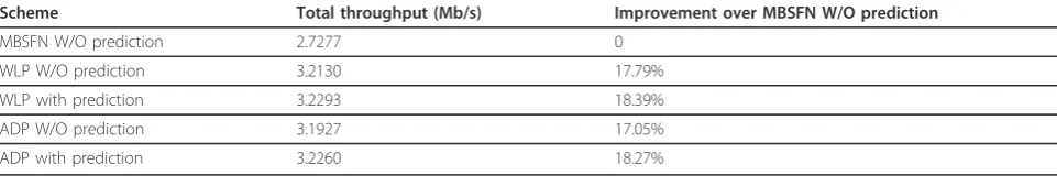
D. Simulation with channel prediction
The simulation results of the ADP with channel predic-tion are given in Table 6. Compared with MBSFN with-out channel prediction, the ADP with channel prediction can improve 18.27% of the total throughput of the CoMP users.
The total throughput of ADP without channel delay is 3.2895 Mb/s (shown in Table 4), and that of ADP with channel delay is 3.1927 Mb/s (shown in Table 5), so there is 3% performance loss by channel feedback delay. If the channel prediction scheme is used in ADP, the total throughput is 3.226 Mb/s, so the performance loss is 2%. The simulation results prove that the perfor-mance loss can be reduced by channel prediction.
E. Analysis on feedback overhead
In the downlink CoMP withKBSs cooperation, one BS is the serving BS, and the otherK -1 BSs are coordinated
BSs. The precoding vectors are quantized with C bits, so the PMI feedback is C bits. The adjustment factor set has four elements, so the ADP will use 2 bits to feed back the adjustment factor index. Table 7 is the feedback overhead of ADP compared with that of WLP and MBSFN.
The number of feedback bits of WLP and ADP is lin-ear with K, and that of MBSFN is independent of K. however, the feedback overhead of ADP will be less than that of WLP whenC> 1. In the simulation, k= 2, andC= 2, ADP reduces by 20% the number of feedback bits compared with WLP; if k = 3, and C = 4, ADP reduces by 43% compared with WLP.
VI. Conclusions
This article proposed an adaptive distributed precoding scheme for downlink CoMP systems with limited feed-back. The proposed scheme takes advantage of the space-time characteristics of the distributed MIMO channel of the CoMP systems. The serving BS can get the optimal precoding vector via PMI feedback. Each coordinated BS adjusts the precoding vector based on the precoding vector used in the previous frame and the adjustment factor fed back by the user. The feedback overhead is reduced, since the user does not need to feed back the PMI for coordinated BSs. However, the precoding vector used in each BS still can be adjusted according to the local channel state, which can maxi-mize the received SNR of user and coherent combina-tion receiving can be used. The simulacombina-tion results verify that the ADP can achieve better performance than Table 4 Total throughput of CoMP users comparison
Scheme Total throughput (Mb/s) Improvement over MBSFN
MBSFN 2.7326 0
Figure 4Throughput CDF curve comparison.
0 1 2 3 4 5 6
Figure 5Throughput CDF curve comparison with 3 TTI delay.
Table 5 Total throughput of CoMP users comparison with 3 TTI delay
Scheme Throughput (Mb/s) Improvement over MBSFN
MBSFN 2.7277 0
WLP 3.2130 17.79%
MBSFN, and reduce the feedback overhead compared with WLP. So the proposed scheme achieves a good tra-deoff between system performance and system feedback overhead. The performance of the all the schemes is degenerated if it has feedback delay, however, the per-formance loss can be compensated by the channel state prediction. It should be noted that the proposed ADP scheme makes the user equipment compute the optimal adjustment factor for coordinated BSs, which add some computational complexity for the user equipment.
Abbreviations
ADP: adaptive distributed precoding; BS: base station; CSI: channel state information; CDF: cumulative distribution function; MBSFN: multicast/ broadcast over single frequency network; OFDMA: orthogonal frequency division multiplexing access; PMI: precoding matrix index; RN: relay node; RRU: remote radio unit; SNR: signal to noise ratio; TTI: transmission time intervals; WLP: weighted local precoding.
Acknowledgements
This work is supported by the National Key Technology R&D Program of China (2010ZX03003-001-01) and Fundamental Research Funds for the Central Universities
Author details
1
Beijing University of Posts and Telecommunications, Beijing, China2Queen Mary, University of London, London, UK3Nanchang University, Nanchang,
China
Competing interests
The authors declare that they have no competing interests.
Received: 1 November 2010 Accepted: 8 June 2011 Published: 8 June 2011
References
1. M Sawahashi, Y Kishiyama, A Morimoto, D Nishikawa, M Tanno, Coordinated multipoint transmission/reception techniques for LTE-advanced [Coordinated and Distributed MIMO]. IEEE Wireless Commun.17, 26–34 (2010)
2. R1-090942,Aspects of Joint Processing for Downlink CoMP, 3GPP TSG RAN WG1 #56 meeting, Athens, Greece, February 9-13, 2009
3. R1-090882,Per-cell precoding methods for downlink joint processing CoMP, 3GPP TSG RAN WG1 #56 meeting, Athens, Greece, February 9-13, 2009 4. R Mudumbai, J Hespanha, U Madhow, G Barriac, Scalable feedback control
for distributed beamforming in sensor networks, inProceedings of the International Symposium on Information Theory (ISIT 2005), 2005, pp. 137–141
5. R Mudumbai, J Hespanha, U Madhow, G Barriac, Distributed Transmit Beamforming Using Feedback Control. IEEE Trans Inform Theory56, 411–426 (2010)
6. W Tushar, DB Smith, Distributed transmit beamforming based on a 3-bit feedback system, inProceedings of the 11th IEEE International Workshop on Signal Processing Advances in Wireless Communications, 2010, pp. 1–5 7. S Shuo, JS Thompson, C Pei-Jung, PM Grant, Improving the One-Bit
Feedback Algorithm for Distributed Beamforming,in WCNC, 2010 IEEE, pp. 1–6
8. Z Yi, R Adve, L Teng, Beamforming with limited feedback in amplify-and-forward cooperative networks. IEEE Trans. Wireless Commun.7, 5145–5149 (2008)
9. P Fertl, A Hottinen, G Matz, Perturbation-Based Distributed Beamforming for Wireless Relay Networks,IEEE GLOBECOM 2008. IEEE, 2008, pp. 1–5 10. JM Paredes, BH Khalaj, AB Gershman, Cooperative Transmission for Wireless
Relay Networks Using Limited Feedback. IEEE Trans Signal Process.58, 3828–3841 (2010)
11. BC Banister, JR Zeidler, A simple gradient sign algorithm for transmit antenna weight adaptation with feedback. IEEE Trans Signal Process.51(5), 1156–1171 (2003)
12. BC Banister, JR Zeidler, Feedback assisted transmission subspace tracking for MIMO systems. IEEE J Select Areas Commun.21(3), 452–463 (2003) 13. BC Banister, JR Zeidler, Feedback assisted stochastic gradient adaptation of
multiantenna transmission. IEEE Trans Wireless Commun.4(3), 1121–1135 (2005) 14. FZ Merli, W Xiaodong, GM Vitetta, Low-Rate-Feedback-Assisted
Beamforming and Power Control for MIMO-OFDM Systems. IEEE Trans Veh Technol.59(1), 225–234 (2010)
15. I Thibault, GE Corazza, L Deambrogio, Random, deterministic, and hybrid algorithms for distributed beamforming, inProceedings of 5th Advanced satellite multimedia systems conference (ASMA) and the 11th signal processing for space communications workshop (SPSC), 2010, pp. 221–225
16. V Lau, Y Liu, TA Chen, On the design of MIMO block-fading channels with feedback-link capacity constraint. IEEE Trans Commun.52(1), 62–70 (2004) 17. R1-092833, Discussions on CoMP Cooperating Set,3GPP TSG-RAN
WG1Meeting #57bis, Los Angeles, USA, 29 June-3 July, 2009
18. R1-090696, Considerations on precoding scheme for DL joint processing CoMP,3GPP TSG RAN WG1 #56 Meeting, Athens, Greece, 9-13 Feb, 2009
doi:10.1186/1687-1499-2011-8
Cite this article as:Zhanget al.:Vector perturbation based adaptive distributed precoding scheme with limited feedback for CoMP systems. EURASIP Journal on Wireless Communications and Networking20112011:8.
Table 6 Total throughput of CoMP users comparison with channel prediction
Scheme Total throughput (Mb/s) Improvement over MBSFN W/O prediction
MBSFN W/O prediction 2.7277 0
WLP W/O prediction 3.2130 17.79%
WLP with prediction 3.2293 18.39%
ADP W/O prediction 3.1927 17.05%
ADP with prediction 3.2260 18.27%
Table 7 Feedback overhead comparison
Scheme Feedback information Feedback bits
MBSFN One PMI forKBSs C
WLP One PMI for each BSs
One phase facor for coordinated BSs
C+ (C+ 1) × (K- 1)
ADP One PMI for serving BSs
One adjustment factor for coordinated BSs