Comparative Study between PID-controller
and Fuzzy Logic Controller of a Novel
Flyback Converter
Subhrajyoti Modak
1, Goutam Kumar Panda
2Pradip Kumar Saha
3PG Student [Power Electronics and Drives], Dept. of EE, Jalpaiguri Govt. Engineering [Autonomous] College, Jalpaiguri, India.1
Professor & HOD, Dept. of EE, Jalpaiguri Govt. Engineering [Autonomous] College, Jalpaiguri, India.2 Professor, Dept. of EE, Jalpaiguri Govt. Engineering [Autonomous] College, Jalpaiguri, India.3
ABSTRACT: In this paper, proportional–integral–derivative (PID)-based Fly-back converter and fuzzy-type controllers are compared for 220V A.C input and 440 D.C output flyback converter operating in discontinuous conduction mode (DCM).Design of fuzzy controllers is based on heuristic knowledge of converter behavior, and tuning requires some expertise to minimize unproductive trial and error. The design of PID control is based on the frequency response of the converter. For the flyback converter, the performance of the fuzzy controller was superior in some respects to that of the PID controllers. The fuzzy controller was able to achieve faster transient response in most tests, had a more stable steady-state response, and was more robust under some operating conditions. MATLAB/Simulink software is used for implementation and simulation results show the performance variations.
KEYWORDS: Voltage Mode Control, Current Mode Control, Discontinuous Conduction Mode, Metal Oxide Semiconductor Field Effect Transistor.
I.INTRODUCTION
For low power applications,the flyback converter is more attractive than the boost converter because of its simplicity lt provides the isolation, start-up, and short-circuit protection by a single switch.
The commonly used fly-back converter requires a single controllable switch like, MOSFET and the usual switching frequency is in the range of 100 kHz. In [2] addresses a novel approach for designing and modelling of the isolate fly back converter. Modelling is done without parasitic as well as with parasitic components. A detailed analysis, simulation and different control strategy are conferred for fly back converter in continuous conduction mode (CCM). To verify the design and modelling at primary stage, study of the converter is practiced in CCM operation for input AC voltage 230V at 50Hz and output DC voltage of 5V and 50W output power rating using PSIM 6.0 software. Simulation result shows a little ripple in output of the converter in open loop. Finally in order to evaluate the system as well as response of the controller, fly back converter is simulated using MATLAB. This work, highlighting the modelling when the system have transformer and facilitate designers to go for it when they need one or more than one output for a given application up to 150W.Ref. [4] the circuit topology of fly back converter is simplest if we compare it with other SMPS circuits. The input given to the converter is generally unregulated dc voltage which is obtained by rectifying the ac voltage followed by a capacitor filter .Fly back converters use a transformer so that they can give single or multiple isolated output voltages. Ref. [5] but if we talk about energy efficiency (η), fly back converter is not good as compared with other SMPS circuits though its topology is very simple. Fly back can be operated in two different modes:
1. Continuous conduction mode (CCM) 2. Discontinuous conduction mode (DCM)
Ref. [1] if the application demands high voltage and low current output then DCM is mostly recommended. Meanwhile, CCM is recommended for low voltage and high current output applications.
polarity and the same ground reference for the input and output. MOSFETs are used as a switching device in low power and high frequency switching applications.These converters are now being used for various applications, such as Switched Mode Power Supply (SMPS) etc. In Ref [6] attempts to present designing and tuning of Fly back converter for constant voltage output.
II. SYSTEM MODEL AND OPERATION
Figure1.Proposed model of Fly –back converter
Modes of Operation and Analysis:
In Fly-back converter power transformer is used for isolation between a primary side and a secondary side. There are basically two mode of operation.
Mode 1 (Switch is closed): When switch „S‟ is on, the primary winding of the transformer gets connected to the input
supply with its dotted end connected to the positive side.
At this time the diode „D‟ connected in series with the secondary winding gets reverse biased due to the induced voltage in the secondary (dotted end potential being higher).
Thus with the turning on of switch „S‟, primary winding is able to carry current but current in the secondary winding is blocked due to the reverse biased diode. The flux established in the transformer core and linking the windings is entirely due to the primary winding current.
Figure2.Mode I Operating Modes [When switch is closed]
Figure3.Mode II Operating Modes [When switch is open]
III. SIMULATION AND RESULT DISCUSSION.
The Simulink Schematic of fly-back converter with analog PID controller is shown in figure 4. The output voltage is sensed Vout and compared with the input voltage Vref. An error signal is produced which is processed through PID
controller to generate a control voltage. The control voltage is used to feed to the PWM generator for control of switch. The PID controller has two parameters namely KP and KI and Kd.
Figure 4.Simulation model of Fly-back converter for closed loop control (PID )
Figure 5.Closed loop response of Fly-back converter (voltage) where Kp=0.0111 Ki=0.019,Kd=0.5
Where the values of parameter are, Input voltage [Vin]=220 volts, Output voltage [Vout]=440volt, Switching
frequency=25kHz, Inductor value=47.60mH, filter capacitor=600µF, current=0.375A.
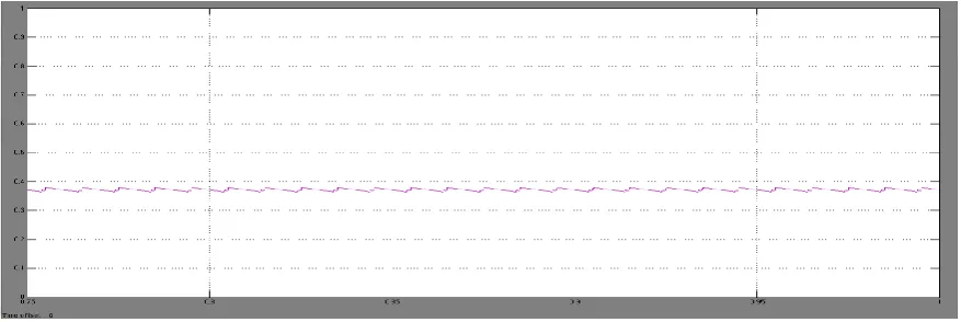
Figure 6.Closed loop response of Fly-back converter (current) where Kp=0.011 ,Ki=0.019.,Kd=0.5
Therefore output values shows, there are variation in output voltage, and fluctuation is less, and output current is 0.375A.
TABLE- I
S.No Kp ki Kd O.S% Settling
time
Rise time
1 0.0012 0.019 0.02 15 0.26 0.01
2 0.0015 0.019 0.02 7.5 0.03 0.01
3 0.0011 0.019 0.1 10 0.2 0.01
4 0.0111 0.019 0.05 8 0.04 0.01
Table I shows the various values of over shoot, settling time ,rise time for output voltage When Values of kp and ki where kept changing as shown, and the output current[I] was seen having constant value 0.375A.
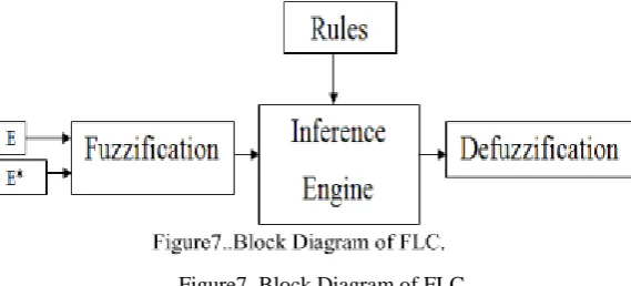
inference engine and defuzzification. The two FLC input variables are the error E and change in error E*. Depending on membership functions and the rules FLC operates.
Figure7..Block Diagram of FLC.
A. Fuzzification- The membership function values are assigned to the linguistic variables using seventeen fuzzy subsets. Table-I shows the rules of FLC. E and E* are input variables, where E is the error between the reference and actual voltage of the system, E* is the change in error in the sampling interval.
B. Inference Engine- Mamdani method is used with Max-Min operation fuzzy combination. Fuzzy inference is based on fuzzy rules. Rules are framed in inference engine block. The output membership function of each rule is given by MIN (Minimum) operator and MAX (Maximum) operator.
C. Defuzzification- The output of fuzzy controller is a fuzzy subset. As the actual system requires a non fuzzy value of Control. defuzzication is required. Defuzzifier is used to convert the linguistic fuzzy sets back into actual value. The membership functions of error (E), change in error (E*) and Duty ratio (D) are shown in fig. 6, 7, 8.Fig.9 shows the representation of the typical Rule Surface of fuzzy logic controller.
TABLE-II
RULE TABLE FOR FLC
Figure 8 shows the membership function given for the Error, i.e. the linguistic values or names given to the various range of input error. The error value is being taken by comparing constant output power provided to the converter,
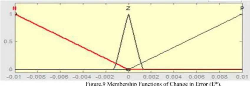
Figure 9 shows the membership function of the change in error, the value to change in error is given by the taking the difference of the error value and the error value after a unit delay. And the range of change in error is being set according to the need of control the output of the fuzzy logic control.
Figure.10 Membership Functions of Duty Ratio (D).
Figure 11 Surface view of Rules of FLC.
Figure 11 shows the surface view of rules given to the fuzzifier for the processing of the membership functions by the inference engine and finally passed to the defuzzifier to produce the relative output in terms of duty ratio. The various output values with respect to the both the inputs i.e. error and change in error can be understood here easily.
Fig.12 Proposed Converter with Fuzzy –logic controller (FLC)
In fig.12, for the same input voltage the converter is controlled by the newly designed FLC now 399.4 V output voltage is obtained.
Figure 13 shows the output voltage from the converter to the load, as for the most of the system the fixed output voltage is required. And for this system the main aim was to convert the input for the usable output voltage. And here we are getting the desired output voltage waveform
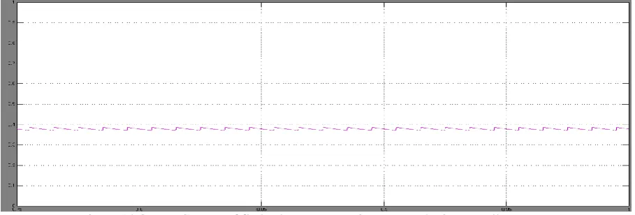
Figure 14 Output Current of fly back converter using Fuzzy –logic controller
Therefore, Fly-back converter with fuzzy logic control is simulated. And high step-up voltage gain is achieved. As the output voltage of the converter with FLC has minimum overshoot and produces a constant output current shows the better performance compared to the converter with PID controller.These studies could solve many types of problems regardless on stability because as we know that fuzzy logic controller is an intelligent controller to their appliances. Additionally, the switch voltage stress is reduced, thus a switch with low voltage ratings can be selected.
IV. CONCLUSION
Here Fly-back converter with fuzzy logic control is simulated and compering with PID controller. A high step-up voltage gain is achieved. As the output voltage of the converter with FLC has minimum overshoot and produces a constant output current shows the better performance compared to the converter with PID controller.
Further it can be simulated with different types of other non model and hybrid control such as artificial neural network, genetic algorithm, fuzzy sliding mode, fuzzy PI and others can be used for advanced tuning and to check the constant output voltage with least ripple and to support different appliances with different voltage ratings.
REFERENCES
[1] B.Baha, “Analysis and control of a cross-regulated multi-output forward quasi-resonant converter,” IEEE Proc.-Circuits Devices Syst., vol. 146, no. 5, pp. 255-262,October 1999.
[2]P.Dananjayan,V.Sriram,C.Chellamithu, “ A flyback constant frequency ZCS-ZVS quasi-resonant converter,” Elsevier Microelectronics journal, vol 29, pp.495-504,1998.
[3] O. Garcia, P. Alou, J. A. Oliver, J. A. Cobos, J. Uceda, and S. Ollero, “AC/DC converters with tight output voltage regulation and with a single control loop,” in Proc. Appl. Power Electron. Conf. (APEC), 1999, pp. 1098–1104.
[4].T. Chen, W. Lin, and C. Liaw, “Dynamic modeling and controller design of flyback converter,” Aerospace and Electronic Systems, IEEE Transactions on, vol. 35, no. 4, pp. 1230–1239, 1999
[5].Singh and G. D. Chaturvedi, “Comparative performance of isolated forward and flyback ac-dc converters for low power applications,” in Power System Technology and IEEE Power India Conference, 2008. POWERCON 2008. Joint International Conference on. IEEE, 2008, pp. 1–6.
[6]S.Arulselvi,K.Deepa,G.Uma, “ Design, analysis and control of a new multi-output flyback CF-ZVS-QRC,” in Proc. IEEE/ICIT Conf, Hongkong,pp.413-419,December-2005.
BIOGRAPHY
Prof. Gautam Kumar Panda, Professor and Head, Department of Electrical Engineering, Department of Electrical Engineering, Jalpaiguri Government Engineering College, Jalpaiguri,WB- 735102, BE (Electrical) from J.G.E. College, Jalpaiguri, M.E.E (Electrical) Specialization: Electrical Machines & drives from Jadavpur University.PhD from University of North Bengal. FIE, MISTE, Certified Energy Auditor