Distributed Mobility Management solutions for next
mobile network architectures
Luca Cominardi
IMDEA Networks Institute and Universidad Carlos III de Madrid, Legans, Spain
E-mail: [email protected]
Abstract—The architecture of current operator infrastructures is being challenged by the non-stopping growing demand of data hungry services appearing every day. Deployed operator networks are focused on providing mobile services to users, relying on hierarchical architectures and protocols, such as Proxy Mobile IP, which force all the traffic to and from the terminals to traverse specific gateways connecting the network to the Internet. Such approaches pose several scalability problems when dealing with high demanding users. This has triggered to study how to provide mobility services in a flatter network architecture, enabling local access to the Internet, in order to reduce the amount of traffic traversing the core. Due to the novelty of these ideas, several possible solutions are being discussed and evaluated. This work aims at comparing the three more prominent families of solutions currently discussed at the IETF, providing an analysis of their scalability characteristics, both from an analytic and experimental point of view.
I. INTRODUCTION
Packet-based mobile networks have experienced a huge success in the last years, with the number of subscribers and traffic volume increasingly growing. Some reports [1] show that the mobile traffic growth will not decelerate, but increase 11-fold from 2013 by the end of 2018.
Among the many efforts that mobile operators are making to increase their benefits, we can highlight improving their infrastructure to meet users’ demands while reducing the associated deployment and operational costs. In order to do so, three major trends can be identified: i) Enhancement of the wireless access, by using more advanced medium access and coding technologies like LTE and LTE-A; ii) migration towards Software Defined Networks (SDN), allowing a more flexible and centralized control of the network, and; iii)
flattening of the network architecture, distributing the load in the access network and avoiding traffic to always traverse the same entities (i.e., potential single points of failure). Here we focus on the latter, that is, on architectural approaches towards an efficient flattening of existing mobile networks.
Current architectures for mobile and cellular networks are highly centralized and hierarchical. The advantage of the centralized approach resides in its simplicity, because the central entity, anchoring mobile nodes’ traffic, can follow the user movements by simply re-routing the packets over tunnels created with the access router where the mobile node (MN) is currently connected. However, the mobility anchor represents a single point of failure, it poses scalability issues (i.e., it is the cardinal point for the control and data plane for million users) and, in general, it leads to sub-optimal paths between
the mobile nodes and their communication peers (also known as correspondent nodes, CNs).
One paradigm, called Distributed Mobility Management (DMM), has recently gained traction as a way of designing a flat mobility architecture. Both 3GPP and IETF, which are the main standardization bodies in this area, are already looking at DMM-alike solutions. In this paper, we explore three different kinds of solutions from an analytic and experimental point of view. These solutions cover pretty much the solution space analyzed today by the IETF and the research community: i)
IP mobility based, ii)SDN based, and iii)routing based. For each of these families we have designed and implemented a full solution, which allows us to evaluate, assess and compare them. This analysis permits to better understand the pros and cons of each approach, depending on the deployment use case. The rest of the paper is organized as follows: Section II gives a background on DMM and SDN, Section III describes how the DMM solutions work, Section IV provides a detailed analysis while Section V reports on experimental results. Finally, Section VI concludes the paper.
II. BACKGROUND
The IETF1 DMM Working Group is currently the main venue where proposed solutions are being discussed. In the past decade, several network-layer mobility protocols have been standardized [2]–[6]. All these protocol achieve mobility by employing a mobility anchor to allow a mobile node to remain reachable after it has moved to a different network. The anchor point, among other tasks, ensures connectivity by forwarding packets destined to, or sent from, the mobile node. The mobility anchors are usually centrally deployed in the sense that an operator network have a small number of these anchors and the traffic of millions of mobile nodes are typically managed by the same anchor. An example of such operator network is the one defined by Third Genera-tion Partnership Project (3GPP) network. Distributed mobility management (DMM) is an alternative to the above centralized deployment.
Mobile users are, more than ever, consuming Internet content including that of local Content Delivery Networks (CDNs). Such traffic imposes new requirements on mobile core networks for data traffic delivery. To prevent exceeding the available core network capacity, service providers need to
implement new strategies such as selective IP traffic offload through alternative access networks such as Wireless Local Area Network (WLAN) [7]–[9]. In addition, a gateway selec-tion mechanism takes the user proximity into account within the Evolved Packet Core (EPC) [10].
LIPA and SIPTO [9] enable data traffic offload at appro-priate points in the Radio Access Network (RAN) in a highly cost-efficient manner leading to an increased system scalability and enhance the operators flexibility to cope with the growing mobile data traffic demanded. LIPA allows an UE, connected in a residential or corporate deployment, to directly connect to other devices and services in the local network, relieving this portion of data traffic from the mobile operator’s core network. LIPA breakout takes always place at the Local Gateway (L-GW) located in the local/home network. SIPTO, on the other hand, offloads selective IP traffic to the Internet at the L-GW. When the UE is connected to a macro-cellular network, SIPTO offload takes place at or above the RAN. By breaking out selected traffic closer to the edge of the network, operators may avoid overloading their scarce resources, as well as avoid inefficient routing in the mobile backhaul network.
Both traffic offloading and CDN mechanisms could benefit from the development of mobile architectures with fewer hierarchical levels introduced into the data path by the mobility management system. This trend of ”flattening” the mobile net-works net-works best for direct communications among peers in the same geographical area. Distributed mobility management in the flattening mobile networks would anchor the traffic closer to the point of attachment of the user. Indeed, mobility patterns indicate that mobile nodes often remain attached to the same point of attachment for considerable periods of time [11]. Specific IP mobility management support is not required for applications that launch and complete their sessions while the mobile node is connected to the same point of attach-ment. However, currently, IP mobility support is designed for always-on operation, maintaining all parameters of the context for each mobile subscriber for as long as they are connected to the network. This can result in a waste of resources and unnecessary costs for the service provider. Infrequent node mobility coupled with application intelligence suggest that mobility support could be provided selectively such as in [12] and [13], thus reducing the amount of context maintained in the network.
An IP-layer mobility management protocol is typically based on the principle of distinguishing between a session identifier and a forwarding address and maintaining a mapping between the two. In Mobile IP [3], the new IP address of the MN after the node has moved is the forwarding address, whereas the original IP address before the MN moves serves as the session identifier. The location management information is kept by associating the forwarding address with the session identifier. Packets addressed to the session identifier will first route to the original network, which redirects them using the forwarding address to deliver to the session. Redirecting packets this way can result in long routes. An existing host-based optimization routes the packets directly to the host using
its forwarding address.
In centralized mobility management, the location informa-tion in terms of a mapping between the session identifier and the forwarding address is kept at a single mobility anchor, and packets destined to the session identifier are forwarded via this anchor. In other words, such mobility management systems are centralized in both the control plane and the data plane. Many existing mobility management deployments make use of centralized mobility anchoring in a hierarchical network architecture. Examples are the home agent and local mobility anchor serving as the anchors for the MN and mobile access gateway in Mobile IPv6 [3] and in Proxy Mobile IPv6 [6], respectively. Mobile networks, such as 3GPP EPS networks, also employ centralized mobility management like the Packet Data Network Gateway (P-GW) and Serving Gateway (S-GW).
Mobility management functions may also be distributed in the data plane to multiple networks, so that a mobile node in any of these networks may be served by a nearby function with appropriate forwarding management capability. DMM is distributed in the data plane, whereas the control plane may be either centralized or distributed as described in the following paragraph.
A. Distributed Mobility Management
The IETF DMM working group charter addresses two com-plementary aspects of mobility management procedures: the distribution of mobility anchors towards a more flat network and the dynamic activation/deactivation of mobility protocol support as an enabler to distributed mobility management [14]. DMM may distribute the mobility anchors in the data-plane in flattening the mobility network such that the mobility anchors are positioned closer to the user; ideally, mobility agents could be collocated with the first-hop router. Facilitated by the distribution of mobility anchors, it may be possible to selectively use or not use mobility protocol support depending on whether such support is needed or not. It can thus reduce the amount of state information that must be maintained in various mobility agents of the mobile network. it can then avoid the unnecessary establishment of mechanisms to forward traffic from an old to a new mobility anchor.
In DMM we can categorize network-based solutions accord-ing to the level of distribution of the control plane [14]:
• Partially distributed solutions, which are characterized
by completely distributing the data path among several anchors deployed closer to the end user, but still keeping the control plane centralized.
• Fully distributed solutions, which completely distribute
both the data and control planes (there is no centralized control entity).
Double NAT DMM solution proposed in [16] adopts the concept of an identifier-locator split to solve the routing in the transport network above the mobility anchors. Forwarding downlink packets to the mobile node’s current mobility anchor can be surely achieved using tunnels as already done in both Mobile IP and Proxy Mobile IP solutions. To avoid encapsulation overhead introduced by tunnelling the use of NAT is proposed at both ends of the operator’s transport network. Two new entities, performing address translation from identifier address to locator address and vice-versa, need to be introduced in the network. These entities are referred to as Ingress NAT router and Egress NAT router. Using NAT functionality is required only in the case of downlink traffic, where the Ingress NAT router performs translation of the identifier address into the locator address and it forwards the packets down into the operator’s transport network. The Egress NAT router, on the other hand, translates the locator address back to the identifier address in order to forward the packet to the mobile node. The Egress NAT routers will therefore always be placed closer to the southern edge of the operator’s transport network than the Ingress NAT routers.
P. Seite et al. [17] proposed a distributed mobility traffic management with dynamic user’s traffic anchoring in the networks’ access routers. It relies on a flat architecture where a new entity named Mobility capable Access Router (MAR) is introduced to provide mobility management functions. The MAR has both mobility anchoring and location update func-tional capabilities and can acts as a Home-MAR or as a Visited-MAR for a given mobile node. A Home-MAR is responsible for the allocation of Home Network Prefix, used in this solution instead of HoA, to MN. On the one hand, when an MN moves away from the home network, the Home-MAR is responsible for tracking the mobile node’s location and forwarding packets to the Visited-MAR where the mobile node is currently attached to. On the other hand a Visited-MAR manages the mobility-related signalling for a MN that is attached to its access link. The architecture of this solution relies on a centralized database storing ongoing mobility sessions for the MNs.
B. Software Defined Networking
Software Defined Networking is a networking paradigm that separates the control and the data forwarding planes. Such separation all ows for quicker provisioning and configuration of network connections. With SDN, network administrators can program the behavior of both the traffic and the network in a centralized way, without requiring independently accessing and configuring each of the networks hardware devices. This approach decouples the system that makes decisions about where traffic is sent (i.e., control plane) from the underly-ing system that forwards traffic to the selected destination (i.e., data plane). Among other advantages, this simplifies networking as well as the deployment of new protocols and applications. In addition, by enabling programmability on the traffic and the devices, an SDN network might be much more flexible and efficient than a traditional one.
SDN-Switch SDN-Switch SDN-Switch SDN-Switch
...
SDN Controller Platform
Southbound API
F
ir
e
w
a
ll
Lo
a
d
B
a
la
n
ce
r
R
o
u
tin
g
...
Ap
p
lic
a
tio
n
Ap
p
lic
a
tio
n
Ap
p
lic
a
tio
n
Northbound API
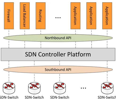
Fig. 1. SDN architecture.
In SDN environments, the Network Controller (NC) is the most important entity and it is responsible to configure the nodes in the network via a common application pro-gramming interface (API), namely Southbound API. IETF FORCES (Forwarding and Control Element Separation) [18] is one of such APIs and defines an architectural framework associated protocols. The goal is to standardize information exchange between the control plane and the forwarding plane. OpenFlow2is another of such APIs and is currently being im-plemented by major vendors, with OpenFlow-enabled switches now commercially available. On the contrary, the external software applications interact with the Network Controller via
aNorthbound APIand, unlike theSouthbound API, there is no
common definition of such interface. The SDN architecture is depicted on Fig. 1 and can be exploited for DMM deployment. Indeed, a DMM protocol can be implemented as application running on top of the SDN controller.
Within IETF DMM Working Group, a first draft has been proposed on combining SDN and DMM. Yang et al. [19] proposes a routing optimization scheme that applies SDN concept to a partially distributed DMM architecture. SDN, which has a flexible way to configure data flow, can provide a solution to support route optimization in DMM paradigm. If the MN changes point of attachment, the mobility is provided by reconfiguring routers’ flow tables for steering the traffic to the MN. Therefore, if data path in the DMM architecture is SDN-capable and a DMM service is available, it is possible to optimize the data path for the MNs getting rid of tunnelling no longer necessary. Besides, [19] gives only an high level statement of the problem, therefore a clean-state SDN/DMM solution will be proposed and analyzed in the following section.
DMM-GW1 DMM-GW2
MN-A MN-A
CMD CN1 CN2
MN DMM-GW Prefix
A 12 Pref1::/64 Pref2::/64
IP-in-IP tunnel
MN-A DMM-GW1 CNs
PBA Rtr. Sol.
PBU Rtr. Adv.
PBU Rtr. Sol.
PBU
PBA Rtr. Adv.
PBA HANDOVER
Data Packets Forwarding before Handover Data Packets Forwarding after Handover
DMM-GW2 CMD
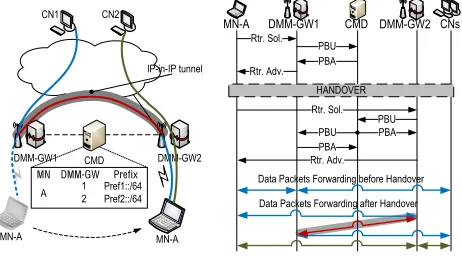
Fig. 2. PMIPv6 based DMM solution.
III. DESCRIPTION OF THEDMMSOLUTIONS
While there exist multiple ways of categorizing existing proposals, here we adopt the following classification: i) IP mobility based, ii) SDN based, and iii) Routing based. The first family is based on classical IP mobility protocols [15], [17], [20]–[23]. In this paper, we focus on network-based approaches in which the user’s terminal is not involved; this category is based on modifications of Proxy Mobile IP (PMIPv6) [6], and hereafter we refer to it as the PMIPv6
based DMM solution. The second follows a Software Defined
Networking paradigm [19], [24]–[26], so we call it SDN
based DMM solution. Finally, the third design is based on
the Border Gateway Protocol (BGP), hence the nameRouting
based DMM solution [27], [28]. A common concept present
in each solution is that the access router does not only provide mere connectivity to the mobile nodes (by being their default gateway), but they are also enhanced with some specific DMM features. For this reason, throughout the paper we refer to a DMM-enabled access router as a DMM-Gateway (DMM-GW).
Note that the first solution described below has been already published [23] while the second and the third are introduced for the first time in this paper. One of the main goals of this paper is to perform a quantitative comparison between the three main solution protocols represented by the solutions described next, so we believe it is useful for the reader to also include a brief description on how the first solution (PMIPv6-based) works for completeness.
A. IP mobility (PMIPv6) based DMM solution
This solution is based on Proxy Mobile IPv6 [6], a network-based IP mobility protocol, which basic principle is the following: each mobile node of the network is assigned an IP prefix from a router in the network core (the topological anchor of that prefix), which keeps track of the location of the mobile node. The access routers in the network signal to the anchor every mobile node’s attachment, so a tunnel can be set-up and maintained between the access router and the anchor for the forwarding of the data traffic. This solution
is conceptually equivalent to the GPRS Tunneling Protocol (GTP) defined by the 3GPP.
In our solution, the DMM-GW is provided with local access to the Internet (i.e., not traversing the anchor in the core). Hence, the DMM-GW acts as a plain access router to forward packets to and from the Internet. Moreover, it is provided with mobility anchoring functions, that is, a DMM-GW is able to anchor the IP flows that an MN initiated while attached to that DMM-GW, and keep them after the MN moves to a new DMM-GW. To maintain the location cache (binding the assigned IP prefixes with the MNs’ location), a control plane only anchor node is used (referred to as Control Mobility Database, CMD).
The operation of the solution (see Fig. 2) starts by a DMM-GW detecting the MN attachment using IPv6 Neighbor Discovery [29] (typically, an IPv6 host sends a Router Solic-itation (RS) message upon joining a link). The DMM-GW notifies the CMD about the MN attachment by means of a Proxy Binding Update (PBU) message (the solution leverages PMIPv6 signaling). In case the CMD is not aware of any session for that MN (i.e., there is no entry on the CMD’s cache for that particular MN), the CMD registers the MN and acknowledges the operation to the DMM-GW with a Proxy Binding Acknowledgment (PBA) message. After a handover, when the CMD receives the PBU from the new DMM-GW, the location cache entry referring to the MN is updated, associating the MN’s location with the new “serving” DMM-GW. The old DMM-GW is included in a list of “anchoring” DMM-GWs. In addition, the CMD instructs the “serving” and “anchoring” DMM-GWs to establish a tunnel between them. By doing so, the ongoing IP flows are not interrupted, but they can be redirected to and from the new MN’s location through the tunnel. The tunnel is used for those flows started before the MN handed over from the previous DMM-GW, whereas new communications are handled by the new DMM-GW as a plain router, that is, without using any tunnels. This dynamic behavior is achieved by the MN obtaining a new IPv6 prefix from each DMM-GW it connects to. Consequently, an MN configures several IPv6 address, one per each visited DMM-GW, and its flows might be anchored at different DMM-GWs.
B. SDN based DMM solution
DMM-GW1 DMM-GW2
MN-A DMM-GW1 CNs
MN-A MN-A
NC
CN1 CN2
OF Rules:
OF Rule Conf. Rtr. Sol. Rtr. Sol.
Rtr. Adv. Rtr. Adv.
OF Rule Conf. Rtr. Sol. Rtr. Sol.
Rtr. Adv.
OF Rule Conf. HANDOVER
Data Packets Forwarding before Handover
Data Packets Forwarding after Handover DMM-GW2 NC
ER3 ER1 ER2
Egress Routers
!"#$$%&'()'*+, !"#$$%&'-)'*+.
!"#$$%&'/)'*+0 OF Rules:
123()'411356.
Routers
OF Rule Conf.
OF Rule Conf.
Rtr. Adv. OF Rule Conf. OF Rule Conf.
OF Rule Conf. OF Rule Conf.
MN DMM-GW ER
A 2
ER1 ER2 ER3
Fig. 3. SDN based DMM solution.
anchored at a pool of k Egress Routers (ERs). After the selection and assignment of IP prefixes (and associated ERs), the NC configures the OpenFlow rules in the MN’s target DMM-GW and in the Egress Routers assigned to it.
Packet forwarding within the network is based on VLANs and it is statically configured. Pre-configured VLAN paths connect Egress Routers with DMM-GWs. Note that these VLAN paths can also be configured by the NC using Open-Flow, but this procedure works in a different time scale and is ruled out of the scope of this work.
Mobility support is achieved by installing OpenFlow rules at the Egress Routers and DMM-GWs, so packets destined or originated from an MN are tagged with the correct VLAN (see Fig. 3). Upon the attachment of an MN to the network, the NC configures Egress Routers to tag MN’s packets with the VLAN connecting the Egress Router with the DMM-GW the MN is attached to. In case of handover, the NC simply needs to rewrite this rule at the Egress Router and the DMM-GW, selecting the correct VLAN that connects the new DMM-GW and the Egress Router assigned to the MN. Note that this solution, unlike the PMIPv6 based one, does not involve any IP tunnels.
This solution is one of the different possible approaches that can be followed with SDN to achieve Distributed Mobility Management. Another solution could be based on rewriting the forwarding of all the network nodes within the domain upon handover [19].
C. Routing based DMM solution
The basic concept of this approach is to remove any anchor from the architecture, letting the standard routing mechanisms of the network to re-establish a new routing map when terminals move. Our solution is based on the general principles proposed in [27], which builds on top of the Border Gateway Protocol (BGP) [30] and the Domain Names System (DNS). This solution considers a flatter network than current deployments by enabling BGP on the access routers (the DMM-GWs), so that they propagate upwards to the their BGP peers the changes in the access links.
DMM-GW1 DMM-GW2
MN-A
CN1 CN2
MN-A DMM-GW1 CNs
Auth.
BGP update Rtr. Adv.
Auth.
BGP Update Rtr. Adv.
HANDOVER
Data Packets Forwarding before Handover
Data Packets Forwarding after Handover
DMM-GW2 Routers
Routers
DNS Query
DNS Query
MN-A
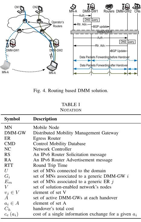
Fig. 4. Routing based DMM solution.
TABLE I NOTATION
Symbol Description
MN Mobile Node
DMM-GW Distributed Mobility Management Gateway ER Egress Router
CMD Control Mobility Database NC Network Controller
RS An IPv6 Router Solicitation message RA An IPv6 Router Advertisement message RTT Round Trip Time
U set of MNs connected to the domain
Gi set of MNs associated to a generic DMM-GWi
Em set of MNs associated to a generic ERj
V set of solution-enabled network’s nodes
vj∈V element of set V
A set of active DMM-GWs at each handover
ai∈A element of set A
Ch handover’s total cost
ce(ai) cost of a single information exchange for a givenai
Upon an MN attachment to a DMM-GW’s access link (see Fig. 4), the access router is able to learn the MN’s DNS name through the authentication process. Next, through a reverse lookup in the inaddr.arpa or ip6.arpa space, the DMM-GW retrieves the IP address (and consequently the IPv6 prefix) associated to the MN’s DNS record and triggers a routing update in the rest of the network, announcing itself as next-hop to reach the MN’s prefix. This is done by originating a new BGP UPDATE message and sending it to its parent routers in the aggregation layer. In case there are no route reflectors, the update must be sent to all BGP peers in the domain. Otherwise, the message will be reflected down to all BGP routers in the local domain.
IV. ANALYTIC EVALUATION
In this section, our solutions are analyzed considering the signaling overhead, the scalability in terms of size of the forwarding tables and the overall handover latency. Table I summarizes the notation used throughout this section.
A. Signaling cost
TABLE II SIGNALING MESSAGES COST
Packet Bytes Description
πPBU 128 Proxy Binding Update with mandatory options only
πPBA 128 Proxy Binding Acknowledgement with mandatory
options only
πoptionanchor 50 Mobility option to indicate the previous DMM-GW
πoptionserving 18 Mobility option to indicate the current DMM-GW
ρDNS 264 DNS query for the MN
ρBGP
update 222 BGP UPDATE message
ρBGP
withdraw 182 BGP WITHDRAW message
σRS 178 Router Solicitation sent to the NC
σRA 218 Router Advertisement sent by the NC
σwrite 264 OpenFlow message for writing a rule
σdelete 232 OpenFlow message for deleting a rule
The first step to formalize the model is the definition of its domain. For this purpose, we defineV ={v1, . . . , vS}as the
set of the nodes vj in the network’s domain enabled with the
mobility functions required by the solution under analysis.
For each solution, when a mobile node hands off from one DMM-GW to another, there are several DMM-GWs involved in the handover operations. We denote this set as A, and its elements as a1, . . . , aN. Clearly, A⊆V, and N =|A|. The
setAchanges at each handover, hence we nameA the set of
the active DMM-GWsin a handover. Its elements are ordered
from the latest to the oldest DMM-GW visited by the MN, and, in particular,a1 is the handoff target anda2is the DMM-GW where the MN is coming from.
We now characterize the handover cost in terms of signaling load. For any givenai∈A, we definece(ai) :A7→Nas the
cost in bytes of each information exchange that involves ai,
including the IPv6 and transport-layer headers, but excluding the data link and MAC layer headers. Therefore, we model the handover cost as follows:
Ch= X
ai∈A
ce(ai), (1)
where ce(ai) is solution-dependent. Its characterization will
be addressed in the following paragraphs.
PMIPv6 based: To properly formalize ce(ai), we detail
some operations from the protocol description (Section III-A). At each handover, the target DMM-GW transmits a PBU message with the PMIPv6 mandatory options only (denoted asπPBU) to the CMD to notify the MN’s new attachment. The
CMD replies with a PBA including the mandatory options (πPBA) and a number of additional options (π
option
anchor), one for
every old DMM-GW that is still anchoring active IP flows. Similarly, the DMM-GW where the MN is coming from, and all the other DMM-GWs that are still anchoring IP flows, receive from the CMD a PBU message with the mandatory options and one additional option (πservingoption) indicating the new serving DMM-GW. These DMM-GWs next send a PBA back to the CMD with the same options to conclude the operation.
Therefore we have:
ce(ai) = (
πPBU+πPBA+ (N−1)π
option
anchor ifi= 1
πPBU+π
option
serving+πPBA+π
option
serving ifi >1
. (2)
Thus, Eq. (1) for the PMIPv6 based case turns into:
ChPMIPv6-based=N(πPBU+πPBA) +
+ (N−1)πoptionanchor+ 2πoptionserving. (3)
In conclusion, this solution’s cost depends linearly on the numberN =|A|of active DMM-GWs.
The value of N depends on both the MN mobility (i.e., handover frequency) and traffic patterns. It is intuitive that the more often the MN changes attachment point, the larger is the number of active DMM-GWs. However, a DMM-GW is eventually de-activated when there are no more MN’s IP flows traversing it. So, the longer the IP flows started by the MN are, the longer is the DMM-GW’s activity interval. Knowing the statistical distribution of the handover rate and how long an IP flow is maintained by the DMM-GW anchoring that flow permits to compute the statistical distribution of the number of active DMM-GWs at any time [23], and thus the size of the setA. In this paper we simplify the problem assuming that an MN spends an exponential time with mean valueµattached to a DMM-GW before handing over to a different one. Besides, we assume that after a handover, an old DMM-GW remains active for an exponential interval of meanλ. Using the results reported in [23], we obtainN, the mean value ofN, as:
N = 2 +λ
µ. (4)
SDN based: In the SDN based solution, the only
DMM-GWs involved during a handover are the target and the last visited DMM-GWs, thus A = {a1, a2} for each handover. From the protocol description (Section III-B), upon a han-dover, the NC writes on the target DMM-GW one downlink rule and as many uplink rules as the number of active ERs for the MN, while the NC writes only one downlink rule on each ER. Moreover, the NC removes the uplink and downlink rules on the DMM-GW the MN just moved from. It is worth mentioning that during a handover, the NC does not delete any rule on the ERs because, by OpenFlow itself [31], one rule can be simply modified instead of deleting and adding a new one. The cost of writing a rule is denoted byσwrite, while
the cost of deleting a rule is denoted byσdelete. Thus, for the
general case of havingkERs, the cost function is defined as follows:
ce(ai) = (
σRS+σRA+ (2k+ 1)σwrite ifi= 1
(k+ 1)σdelete ifi= 2
. (5)
Consequently, Eq. (1) for the SDN based case turns out to be:
ChSDN-based=σRS+σRA+ (2k+ 1)σwrite+ (k+ 1)σdelete, (6)
20 40 60 80 100
100 1000
Handover signalling cost [B/s]
µ [s]
λ = 30 λ = 300 λ = 900
(a) PMIPv6 based solution
20 40 60 80 100
100 1000
Handover signalling cost [B/s]
µ [s]
k = 1
k = 3
k = 5
(b) SDN based solution
20 40 60 80 100
100 1000
Handover signalling cost [B/s]
µ [s]
|V| = 5 |V| = 10 |V| = 15
(c) Routing based solution
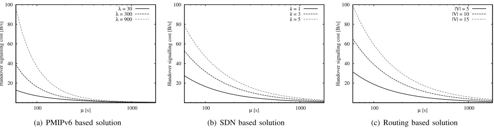
Fig. 5. Handover signaling cost for the three DMM solutions.
Routing based: In the Routing based solution, the set A
is the same as in the SDN based one. During a handover, the DMM-GW where the MN is coming from sends a BGP WITHDRAW message to all the other BGP routers, including the target DMM-GW, while the target DMM-GW sends a BGP UPDATE message to the rest of BGP routers, including the DMM-GW from where the MN is handing off. After these observations we obtain:
ce(ai) = (
(|V| −1)ρBGP
update if i= 1
(|V| −1)ρBGP
withdraw if i= 2
. (7)
The handover then becomes:
ChBGP-based= (|V| −1) ρBGPupdate+ρBGPwithdraw
, (8)
from which it can be observed that the routing solution’s handover cost depends linearly on the size of V.
Signaling cost considerations: Signaling cost is an
impor-tant issue, especially from operators’ viewpoint, so we analyze next the average signaling cost for a single MN, for the three solutions. We consider a residence time µ defined as in the PMIPv6 based solution, and Ch/µ as the solution’s
cost in bytes per second. The size of each message involved in Eq. (2), Eq. (5), Eq. (7) has been measured experimentally (and its value is reported in Table II). The description of the experiments is reported later in Section V.
The signaling cost is reported, for different values of λ, k,|V|, in Fig. 5(a) for the PMIPv6 based solution, in Fig. 5(b) for the SDN based, and in Fig. 5(c) for the Routing based one. We observe a performance degradation on the PMIPv6 based solution in case of high mobility, that is, large λ/µ values. In order to cope with this limitation, the deploy-ment of such solution should jointly consider the coverage area and the level of mobility of MNs. That is, the DMM-GW’s coverage area should not be too small in order to reduce the number of active DMM-GWs. Such information is usually available to operators.
The SDN based solution behaves in a more predictive way, as it only depends on the valuekand it is independent of the traffic pattern of MNs. Operators have the profiles of each MN, therefore the valuekcan be also adapted on an MN basis. As a result, the network can be managed in a smarter way and a
higher network’s efficiency can be achieved by spreading the MNs on multiple ERs.
In the Routing based solution, |V| is the parameter that affects more the overall cost. Consequently, an operator willing to deploy this solution should split the global domain in several smaller local domains, i.e., implementing route reflectors, reducing in this way the total traffic exchange.
B. Forwarding table size
We characterize next the size (S= #rules) of the forward-ing table of the involved network nodes. We defineU as the set of subscribers connected to the domain, and, Gi⊆U the
set of subscribers associated to a generic DMM-GWi.
PMIPv6 based: In the PMIPv6 based solution, a DMM-GW
assigns a unique IPv6 prefix from its own prefix pool to each MN connected to it. Therefore, the DMM-GW must maintain a routing entry for that prefix as long as the MN keeps using it, regardless the MN is still connected to that DMM-GW or handed off to another DMM-GW. In the former case, the route points to the access link where the MN is attached to, whereas in the latter it points to the tunnel interface that connects to the DMM-GW where the MN moved. Thus, a DMM-GW i must maintain at least the downlink route for all theGi MNs
attached to it, due to the prefix it advertised directly to them. In addition, for all these MNs, the DMM-GW maintains an uplink and downlink route for all the MN’s active prefixes that were advertised previously by other DMM-GWs. As described in Section IV-A, an MN has on averageN−1active DMM-GWs beyond the current serving one, hence N−1 active prefixes advertised by old DMM-GWs. In conclusion, the number of routing entries in a DMM-GW is given by:
SPMIPv6-based
DMM-GWi = (2N−1)|Gi|. (9)
SDN based: For the case of the SDN based solution, we
asEm⊆U. As a result, the size of the forwarding table turns
into:
SSDN-basedEm =|Em|. (10)
It is worth highlighting that this is the best achievable result. In fact, the smallest number of rules necessary to properly identify a single MN is one rule. On the contrary, the forwarding table on a DMM-GW depends on k and on Gi. Indeed, the NC writes k+ 1 rules on the target
DMM-GW for each associated MN, leading to:
SDMM-GWSDN-based
i = (k+ 1)|Gi| . (11)
Regarding EmandGi, we can safely assume:
|Em| |Gi| ∀i, m , (12)
that is the number of MNs managed by an ER is many orders of magnitude larger than the number of MNs managed by a single DMM-GW. Therefore,kdoes not present any scalability problem for the forwarding table’s size.
Routing based: In this case, each MN is assigned a unique
IPv6 prefix, therefore all the routers in the domain need to have a routing entry for that prefix. Thus, each routervj ∈V
has |U|routing entries:
SRouting-based
vj =|U| ∀vj∈V . (13)
Prefix aggregation may help in reducing the size of the routing table if the users are static, but still more specific routes might be necessary to track users movements.
C. Handover latency
Next, we study how the protocol operations affect the handover latency for each of the three DMM solutions.
The handover delay analysis can be split into three sub-problems:i)the Layer-2 handover, including the time elapsed since the old radio link is torn down until the new one is established,ii)the Layer-3 configuration, considering the time required by the MN to obtain network layer connectivity (including the Layer-2 handover), andiii)the IP flow recovery, i.e., the interval during which an IP flow is interrupted due to the handover (including both the Layer-2, the Layer-3 config-uration, plus then the remaining actions performed within the network to ensure IP session continuity).
In all our protocols, the Layer-2 handover does not depend on the specific solution and it is the same for all of them, thus we omit including it in the equations. Nevertheless, in Section V we provide the results obtained in our experiments.
PMIPv6 based: The MN establishes the Layer-3
connectiv-ity by requesting an IPv6 prefix with a Router Solicitation (RS) message. The DMM-GW, before sending to the mobile node the IPv6 prefix information in a Router Acknowledgement (RA), performs a two-way message exchange with the CMD to register the MN presence and the assigned prefix. As a result, the time required by the MN for the Layer-3 configuration is mainly due to the round trip time (RTT) between the MN and the DMM-GW for the RS/RA exchange and another RTT between the DMM-GW and the CMD for the Proxy Binding
Update (PBU)/Proxy Binding Acknowledgement (PBA) sig-naling. This Layer-3 latency can then be expressed as:
TL3PMIPv6-based=RTTMN-DMMGW+RTTDMMGW-CMD. (14)
Since the MN acquires a new IPv6 prefix for each visited DMM-GW, IP flows initiated before the handover use a previous prefix, and thus they require an additional setup in the network. To do so, the CMD instructs all the previous active DMM-GWs with parallel PBU/PBA sessions after the PBU from the new DMM-GW is received. Such DMM-GWs re-build the data path for the IP flows with a tunnel to the current MN’s DMM-GW. Let’s assume RTTDMMGW-CMDfrom
the CMD to all the domain’s DMM-GWs to be constant, and the mean delay to transfer a packet from an old DMM-GW to the serving one equal to(1/2)RTTDMMGW-DMMGW. We obtain:
Tflow-recoveryPMIPv6-based=TL2-ho+RTTMN-DMMGW+ (15)
+3
2RTTDMMGW-CMD+ 1
2RTTDMMGW-DMMGW, where RTTMN-DMMGW is the Router Solicitation transmission
time, plus the delivery of the first data packet from the serving DMM-GW to the MN.
SDN based: In this case, the Router Solicitation (RS) sent
by the mobile node upon attachment is intercepted by the target DMM-GW and forwarded to the NC. At this point, the Network Controller (NC) configures the forwarding path in the network by:i)writing the rules on the new DMM-GW and on the Egress Routers (ERs), and,ii)deleting the rules on the old DMM-GW. In this solution, the order plays an important role, indeed, after the configuration of the target DMM-GW and of the ERs, the path in the network is updated and the traffic is finally able to reach the MN. Consequently, to compute the IP flow-recovery time, we can get rid of the time necessary to delete the rules on the last visited DMM-GW. After the configuration phase, the NC generates an RA which is sent back to the DMM-GW and finally forwarded by the latter to the MN. This RS/RA exchange lasts an RTT between the MN and the DMM-GW plus another RTT between the DMM-GW and the NC. On the new DMM-GW, the NC writesk+ 1rules through k+ 1 separate messages, where k is the number of ERs. As a result, the NC takes(1/2) (k+ 1)RTTDMMGW-NC to
configure the new DMM-GW. For the ERs, the NC writes one rule on each ER, taking (k/2)RTTER-NC to update the rules,
whereRTTER-NC is the distance between the ER and the NC.
For simplicity, we considerRTTER-NCas constant for each ER.
Therefore, the Layer-3 configuration latency is:
TL3SDN-based=RTTMN-DMMGW+RTTDMMGW-NC+
+k+ 1
2 RTTDMMGW-NC+
k
2RTTER-NC. (16) After the configuration phase and the reception of the Router Acknowledgement message by the MN, the packets can finally reach the MN, taking a timeTtransport. Hence, the flow-recovery
time is:
MN
DMM-GW1 DMM-GW2 DMM-GW3
CN CMD
Transport IPv6 Network
(a) PMIPv6 based test-bed
DMM-GW1 DMM-GW2 DMM-GW3
802.1Q DP Switch NC
CP Switch
CN
MN
Egress Routers
(b) SDN based test-bed
MN
DMM-GW1 DMM-GW2 DMM-GW3
CN DNS server
BGP Routers
(core)
BGP Routers (access)
(c) Routing based test-bed
Fig. 6. Test-beds configuration.
Routing based: In the Routing based solution, the
DMM-GW detects that the MN has performed a Layer-2 handover and retrieves the IPv6 address for that MN through a DNS query. The DMM-GW then installs a downlink route for the MN, and the IPv6 address is then sent in an Router Acknowledgement (RA) message to the MN, concluding the Layer-3 configuration. Thus we get:
TL3Routing-based=RTTDMMGW-DNS+
1
2RTTMN-DMMGW. (18) After this stage, the old data path in the network to reach the MN no longer exists, therefore the DMM-GW sends BGP UPDATE messages to all its |V| −1BGP peers to create the new path. The messages are sent back-to-back, and we take a constant distance RTTDMMGW-BGPnodes between the DMM-GW
and any BGP peer. As in the SDN based case, we addTtransport
to the flow-recovery time. The overall latency results to be:
Tflow-recoveryRouting-based=TL2-ho+T
Routing-based
L3 + (19)
+|V| −1
2 RTTDMMGW-BGPnodes+Ttransport. V. EXPERIMENTAL VALIDATION
In this section we provide a proof of concept of all the DMM solutions presented in this paper, aiming at assessing their feasibility and performance.
A. Test-bed Description
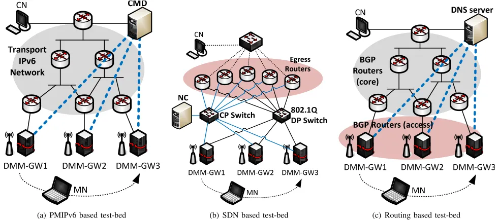
In order to evaluate the three solutions, we deployed three different test-beds based on GNU/Linux machines connected through Ethernet. Each test-bed comprises 3 nodes acting as access routers providing IEEE 802.11b/g wireless access to the MNs. As none of our solutions devises any intervention on the MN, the hardware and software requirements for the MNs are loose, being simply an IEEE 802.11b/g wireless card, and a standard IPv6 stack implementing Neighbor Discovery [29].
For the sake of clarity, employing 802.11 as access technology does not affect our analysis because, as previously described in Section III, the considered DMM approaches are IP-based and Layer-2 agnostic. Therefore, the use of other link layer protocols does not have any significant effect on the results. In the following paragraphs we delve into the solution-specific test-beds description.
1) PMIPv6 based test-bed: The PMIPv6 based test-bed is
depicted in Fig. 6(a). In order to make the scenario more realistic, we added to the test-bed a transport IPv6 network composed by several IPv6 routers. These routers connect the DMM-GWs to the CMD and to the CN. The dashed blue lines in Fig. 6(a) represent the logical interaction between the CMD and the DMM-GWs, and they are in no case a dedicated path between the CMD and the DMM-GWs. The DMM-GWs and the CMD are the only nodes that run our implementation of the PMIPv6 based solution. Such implementation replicates the signaling and operations specified in [15] and briefly summarized in Section III-A.
2) SDN based test-bed: In the SDN based test-bed, in
addition to the DMM-GWs, we added 5 ERs as illustrated in Fig. 6(b). As can be observed from the picture, the DMM-GWs and the ERs are connected each other through two separate networks, one for the control plane (drawn with blue lines) and one for the data plane (the black segments). In the control plane network, a switch realizes the interconnection among all the nodes and also with the NC (see the CP Switch node in Fig. 6(b)). For the data plane, the packet forwarding within the network is based on VLANs and statically configured. Thus, we deployed and configured an 802.1Q-capable switch in the data plane that interconnects all the DMM-GWs and ERs. Moreover, the ERs have a third link used to connect the test-bed to the CN.
0 0.1 0.2 0.3 0.4 0.5 0.6 0.7 0.8 0.9 1
0.01 0.1 1 10
eCDF
Time [s] PMIPv6, N=3
SDN, k=3 Routing, |V|=4
Fig. 7. Flow-recovery time eCDF.
bound API, all the DMM-GWs and ERs run the version 3.10 of Linux kernel. This version of the kernel includes Open vSwitch3 which provides an OpenFlow 1.3 interface. The NC runs Ryu4 as OpenFlow controller. The SDN based solution is therefore implemented as Ryu application (i.e. based on the API provided by the NC). The connection between Open vSwitch and Ryu is performed out-of-band involving TCP for delivering the OpenFlow messages. The application is in charge of all the tasks described in Section III-B.
3) Routing based test-bed: Fig. 6(c) depicts the Routing
based test-bed. The test-bed is composed by the three DMM-GWs and several additional BGP routers. The group of routers marked asBGP Routers (core)connect the DMM-GWs to the DNS server and to the CN. The DMM-GWs are marked as
theBGP Routers (access)group to highlight the fact that they
actively send BGP updates to the rest of BGP peers, while those in the core simply receive the notification and do not redistribute them. The dashed blue lines simply represent the communication between the DNS server and the DMM-GWs, but it is not made over dedicated links.
The Routing based solution employs several implementa-tions. The DNS server is realized with Bind95. The BGP implementation used in all the nodes is from the Quagga framework6. In addition, the DMM-GWs run a custom piece
of software that performs the detection of the wireless events (attachment and detachment), the DNS queries, and it trig-gers the Quagga’s BGP routing daemon to install/remove the local downlink route for the MN. The Quagga daemon then propagates the routing update to all the other BGP speakers, i.e., the whole BGP Routers (core) group and the remaining DMM-GWs.
3http://openvswitch.org/
4http://osrg.github.io/ryu/
5http://www.bind9.com/
6http://www.nongnu.org/quagga/
0.000 0.005 0.010 0.015 0.020 0.025 0.030 0.035
N=2 N=3 N=5 k=2 k=3 k=5 |V|=3 |V|=4 |V|=6
Time [s]
Layer-2 DMM-GW processing CMD processing
NC processing OF rule conf. RA preparation
MN gap DNS query Tx time
Routing-based SDN-based
PMIPv6-based
Fig. 8. Layer-3 latency composition.
B. Experimental Results
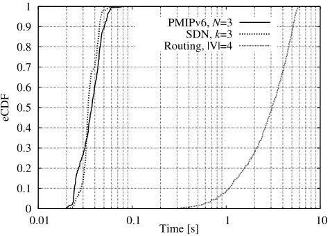
The objective of the experiments is to observe how an MN reacts when a handover occurs, that is, what happens to the data traffic when the MN moves from one DMM-GW to the other. For this purpose, the Correspondent Node (CN) generatespingtraffic destined to the MN every 2ms, which is below the average of MN-CN RTT.
For each implementation, we have measured the three han-dover events introduced in Section IV-C. The measurements are realized with an usual packet capturing tool7 installed in the MN and detailed in the following:
1) The Layer-2 handover is measured as the interval be-tween two IEEE 802.11 control messages:
Deauthen-tication, sent by the MN to the old DMM-GW, and
Association responsereceived by the MN from the new
DMM-GW;
2) the Layer-3 configuration is the time spent since the
Deauthentication message, to the instant when a RA
message is received by the MN8;
3) theIP flow recoveryis measured as the interval between the last pingpacket received or sent by the MN before the handover and the first pingpacket received or sent after the handover.
Table III reports the mean and the standard deviation values of the results forN = 3in the PMIPv6 based test-bed,k= 3 in the SDN based prototype and |V| = 4 for the Routing based one (two BGP routers in the access and two in the core). Fig. 7 depicts the empirical CDF for the values of the
pingrecovery time in the same test scenario. Fig. 8 explores in detail the components of the Layer-3 configuration time for varying values ofN = 2,3,5 in the PMIPv6 based case, k = 2,3,5 in the SDN based case and, |V| = 3,4,6 in the Routing based case.
7Wireshark, http://www.wireshark.org/
8The IPv6 Duplicate Address Detection is disabled since the prefix is
TABLE III
HANDOVER LATENCY EXPERIMENTAL RESULTS
Type of solution Layer-2 handover Layer-3 configuration IP flow recovery Mean (ms) Std. Dev (ms) Mean (ms) Std. Dev (ms) Mean (ms) Std. Dev (ms)
PMIPv6-based N= 3 12.9 4.4 27.7 7.2 37.4 9.9
SDN-based k= 3 12.9 4.4 29.2 4.9 35.6 6.7
Routing-based |V|= 4 12.9 4.4 16.9 3.9 3107 1490
As it can be noticed from the results, all the three solutions take few tens of milliseconds to provide the MN with the IPv6 configuration, and the Layer-2 switch time is the major term. More, we observed a 5ms gap between the instant the MN receives the Association response message, and the time it sends the RS message to the DMM-GW. This gap, denoted “MN gap” in Fig. 8, is not present in the Routing based solution, because the DMM-GW employs a dedicated detection mechanism for the Layer-2 link activation and de-activation. The Routing based solution is thus the quickest to set up the Layer-3 configuration, also because the remaining portion of time is spent for the DNS query and the RA transmission time over the wireless link. In addition, the Layer-3 configuration time is constant for this solution regardless the number of nodes in the network. In the other two solutions, we can separate the component due to message transmission, which depends on the sum of the RTT between the MN and the DMM-GW and the RTT between the DMM-GW and the CMD or NC, respectively for the PMIPv6 based or the SDN based solution. In our laboratory tests, all the nodes are close to each other, and such RTT sum is less than 5ms. In a real deployment, with larger RTT values, the Layer-3 configuration time would tend to approximate the air time plus the distance from the central node to the farthest router involved in the signalling. The rest of components is due to processing at the network nodes and they tend to scale with the number of entities involved in the handover operations. In the PMIPv6 based case, the heaviest burden is on the DMM-GW, because of the tunnels and routes set up, so, the largest the number of previous DMM-GWs, the longer the latency. The CMD is mainly answering to a query, so its task is accomplished much quicker. In the SDN based case, the NC has to compute and send the rules to the ERs. In addition it has to process the RS from the MN and prepare the RA message.
The pingtraffic recovery time, beyond the handover opera-tions, is affected by the tasks distributed in different elements of the network, as routers and switches. For example, packets are queued at the nodes’ interfaces, introducing random delays that are complex to capture. Therefore we limit our analysis on some macroscopic effects that we observed during the experiments. The most remarkable result is that, in the Routing based solution, it takes roughly one hundred times more than in the other two solutions for the ping to be resumed. The reason resides in the implementation choices adopted by the Quagga developers to let the routing daemon react to changes in the routing tables. From a theoretical point of view (see Section IV-C), the new path for the ping packets is ready as
soon as all the routers in the target path receive the BGP UPDATE messages from the DMM-GW, hence, if the UP-DATE messages are sent back-to-back to the BGP peers right upon the new route is added, the interval tends to approximate the RTT with the farthest peer. However, in practice, routing protocols are not designed to react immediately to changes in the network, in order to reduce possible ping-pong effects and the consequent flood of messages that propagate. In this sense, routing protocols do not fit to high mobility scenarios, as those typical of mobile networks. In our prototype, we observed that in the Quagga BGP routing daemon it takes on average 2.9973 seconds since a new route is installed until the daemon starts to distribute the update messages back-to-back. On the contrary, when a route is removed, Quagga reacts on average in 68.1ms. In the other two solutions, thepingrecovery is roughly 10ms higher than the Layer-3 configuration time for the PMIPv6 based solution, and around 6ms for the SDN based one. For the latter solution, the reason is mainly due to the time required by the nodes to receive and install the rules sent by the NC, and then for theping packets to flow from the egress router to the MN. In the PMIPv6 case, old DMM-GWs are notified by the CMD after the new DMM-GW, they update the tunnel parameters and routes to point to the new location and then they can forward packets that flow through the tunnel and finally are delivered to the MN.
VI. CONCLUSION
REFERENCES
[1] CISCO, “Cisco Visual Networking Index: Global Mobile Data Traffic Forecast Update, 2013-2018,” inWhite Paper, Feb. 2014. I
[2] C. Perkinset al., “IP Mobility Support for IPv4,” Aug. 2002, iETF RFC 3344. II
[3] ——, “Mobility Support in IPv6,” Jun. 2004, IETF RFC 6275. II [4] H. Soliman, C. Castelluccia, K. El Malld et al., “Hierarchical mobile
ipv6 mobility management (hmipv6),” Oct. 2008, IETF RFC 5380. II [5] Z. Zhu and R. Wakikawa, “A survey of mobility support in the internet,”
2011, IETF RFC 6301. II
[6] S. Gundavelli, K. Leung, V. Devarapalli, K. Chowdhury, and B. Patil, “Proxy Mobile IPv6,” IETF RFC 5213, August 2008. II, III, III-A [7] K. Lee, J. Lee, Y. Yi, I. Rhee, and S. Chong, “Mobile data offloading:
how much can wifi deliver?” inProceedings of the 6th International
COnference. ACM, 2010, p. 26. II
[8] S. Gundavelli, X. Zhou, J. Korhonen, and G. Feige, “IPv4 Traffic Offload Selector Option for Proxy Mobile IPv6,” 2013, IETF RFC 6909. II [9] Local IP Access and Selected IP Traffic Offload (LIPA-SIPTO),
http://www.3gpp.org/ftp/Specs/html-info/23829.htm. II
[10] 3GPP, “Domain name System Procedures; Stage 3,” 3rd Generation Partnership Project (3GPP), TS 29.274, September 2012. II
[11] G. Kirby, “Locating the user,”Communication International, 1995. II [12] S. Bhandari et al., “DHCPv6 class based prefix,” 2013, IETF draft,
draft-bhandari-dhc-class-based-prefix-05. II
[13] J. Korhonen et al., “IPv6 Prefix Properties,” 2013, IETF draft, draft-korhonen-6man-prefix-properties-02. II
[14] H. Chanet al., “Requirements for Distributed Mobility Management,” Aug. 2014, IETF RFC 7333. II-A
[15] C. J. Bernardos et al., “A PMIPv6-based solution for Distributed Mobility Management,” Jan. 2014, IETF draft, draft-bernardos-dmm-pmip-03. II-A, III, V-A1
[16] M. Liebsch et al., “Distributed Mobility Management Framework and Analysis,” Feb. 2014, IETF draft, draft-liebsch-dmm-framework-analysis-03. II-A
[17] P. Seiteet al., “Dynamic Mobility Anchoring,” May 2014, IETF draft, draft-seite-dmm-dma. II-A, III
[18] J. Halpern et al., “Forwarding and control element separation (forces) forwarding element model,” Mar. 2010, iETF RFC 5812. II-B
[19] H. Yang and Y. Kim, “Routing Optimization with SDN,” Apr. 2014, IETF draft, draft-yang-dmm-sdn-dmm-01. II-B, III, III-B
[20] H. Chanet al., “Enhanced mobility anchoring,” Jul. 2014, IETF draft, draft-chan-dmm-enhanced-mobility-anchoring. III
[21] H. Chan, “Distributed mobility management with Mobile IP,” in
Com-munications (ICC), 2012 IEEE International Conference on, June 2012,
pp. 6850–6854. III
[22] C. J. Bernardoset al., “An IPv6 Distributed Client Mobility Management approach using existing mechanisms,” Jan. 2014, IETF draft, draft-bernardos-dmm-cmip-01. III
[23] F. Giust et al., “Analytic Evaluation and Experimental Validation of a Network-based IPv6 Distributed Mobility Management Solution,”
Mobile Computing, IEEE Transactions on, vol. PP, no. 99, pp. 1–1,
2014. III, IV-A
[24] Ali-Ahmad et al., “An SDN-Based Network Architecture for Ex-tremely Dense Wireless Networks,” inFuture Networks and Services
(SDN4FNS), 2013 IEEE SDN for, Nov 2013, pp. 1–7. III
[25] M. Karimzadehet al., “Applying SDN/OpenFlow in Virtualized LTE to support Distributed Mobility Management (DMM),” in4th International
Conference on Cloud Computing and Services Science, CLOSER 2014.
Portugal: SciTePress, April 2014, p. 86. III
[26] M. Karimzadehet al., “Software defined networking to improve mobility management performance,” in Monitoring and Securing Virtualized
Networks and Services. Springer Berlin Heidelberg, 2014, vol. 8508,
pp. 118–122. III
[27] P. McCann, “Authentication and Mobility Management in a Flat Ar-chitecture,” Mar. 2012, IETF draft, draft-mccann-dmm-flatarch-00. III, III-C
[28] D.-H. Shinet al., “Distributed mobility management for efficient video delivery over all-IP mobile networks: Competing approaches,”Network, IEEE, vol. 27, no. 2, pp. 28–33, March 2013. III
[29] T. Narten, E. Nordmark, W. Simpson, and H. Soliman, “Neighbor Discovery for IP version 6 (IPv6),” RFC 4861, Sep. 2007. III-A, V-A [30] Y. Rekhter, T. Li, and S. Hares, “A Border Gateway Protocol 4
(BGP-4),” RFC 4271, January 2006. III-C
[31] “Openflow switch specification: Version 1.3.0,” Jun. 2012, https://www.opennetworking.org/images/stories/downloads/