PIC BASED SOLAR CHARGING
CONTROLLER FOR BATTERY
Mrs Jaya N. Ingole
Assistant Professor, Department of Electrical Engineering
Priyadarshani Indira Gandhi College of Engineering, Nagpur- Maharashtra [India]
Mrs Dr. Madhuri A. Choudhary
Associate Professor, Department of Electrical Engineering
Vishweshawariya National Institute of Technology, Nagpur – Maharashtra [India]
Dr. R.D. Kanphade
Principal, Dhole Patil College of Engineering, Pune
Abstract:
Solar resource is unlimited the government is trying to implement the use of Solar panels as an energy source in rural and sub urban areas for lighting the street lights, but the battery used to store the power gets affected due to overcharge & discharges. This paper presents the use of PIC16F72 based solar charger controller for controlling the overcharging and discharging of a solar cell. It works by continuously optimizing the interface between the solar array and battery. First, the variable supply is fixed at 12.8V dc—the voltage of a fully charged battery— and linked to the battery point of the circuit. Cut Off of battery from load voltage is 10.8 volt. A PIC16F72 for small size and inbuilt analog inputs is used to determine voltage level of battery and solar panel..It also describes how the disadvantages of analog circuit are overcome by this controller. The flow chart is also provided.
Keywords: Solar energy, Solar charge controller, Inverter, MOSFET,
1.1 Introduction
Sustainable electrical sources like solar photovoltaic arrays are becoming increasingly important as environmentally friendly alternatives to fossil fuels. But, while they’re favorable for the environment, sustainable sources aren’t always easy to apply. These sources are characterized by both stringent peak-power limitations and “use it or lose it” availability. Successful application of sustainable energy sources therefore depends on strict attention to efficiency in both power conversion and energy storage. A charge controller is an essential part of nearly all power systems that charge batteries, whether the power source is PV, wind, hydro, fuel, or utility grid. Its purpose is to keep your batteries properly fed and safe for the long term. A charge controller is a regulator that goes between the solar panels and the batteries. Regulators for solar systems are designed to keep the batteries charged at peak without overcharging. Meters for Amps (from the panels) and battery Volts are optional with most types.
2.1Principle of Solar Battery Charger [1-3]
order to store sufficient magnetic energy for battery charging, which is difficult for the solar cells to provide due to their high internal impedance at low insolation. An improved solar battery charger shown in Fig. 1(c) is proposed by the authors to improve solar energy utilization at low insolation conditions.
Fig 1: Solar Battery Charger
2.2 Working of charge controller:
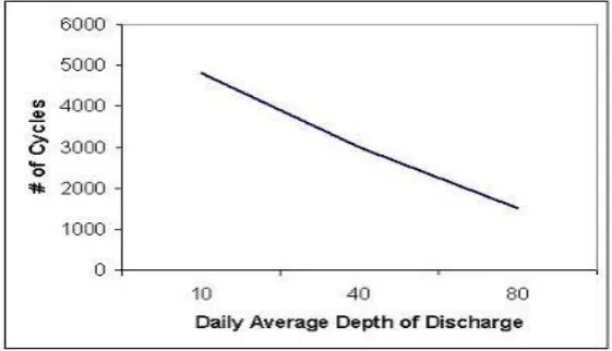
It works by continuously optimizing the interface between the solar array and battery. First, the variable supply is fixed at 12.8V dc—the voltage of a fully charged battery—and linked to the battery point of the circuit. Cut Off of battery from load voltage is 10.8 volt. It is recommended that you never discharge a deep-cycle battery below 50% of itscapacity; however, many battery manufacturers recommend even shallower Depth of Discharge. For off-grid applications, a 25% Depth of Discharge will extend battery life significantly. On the other hand, if you are only using the batteries occasionally, as a backup system, you can factor in a Depth of Discharge of 50% or perhaps more. Fig 2 shows the Daily Average Depth of Discharge.
In fact, the temperature standard for most battery ratings is 77° F. Cold temperatures tend to reduce battery capacity while high temperatures tend to shorten battery life.[4,5]
Fig. 2: Battery Life Based On Depth of Discharge
2.2.1 Typical set points for 12 V lead-acid batteries at 25° C:
High limit (flooded battery) : 14.4 V High limit (sealed battery) : 14.0 V Resume full charge : 13.0 V Low voltage disconnect : 10.8 V Reconnect : 12.5 V
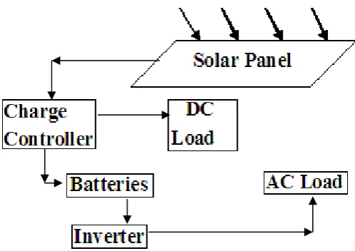
2.2.2 General schematic of a residential PV system with battery storage:-
Fig. 3 General schematic of a residential PV system with battery storage
2.3 Function of charge controllers:
A charge controller is an essential part of nearly all power systems that charge batteries, whether the power source is PV, wind, hydro, fuel, or utility grid. Its purpose is to keep your batteries properly fed and safe for the long term. [6-8]
The basic functions of a controller are quite simple. Charge controllers block reverse current and prevent battery overcharge. Some controllers also prevent battery over discharge, protect from electrical overload, and/or display battery status and the flow of power. Let's examine each function individually.
2.3.1 Blocking reverse current
Photovoltaic panels work by pumping current through the battery in one direction. At night, the panels may pass a bit of current in the reverse direction, causing a slight discharge from the battery. The potential loss is minor, but it is easy to prevent. In most controllers, charge current passes through a semiconductor (a transistor) which acts like a valve to control the current. It prevents reverse current without any extra effort or cost. [9-10]
2.3.2 Preventing overcharge
Preventing overcharge is simply a matter of reducing the flow of energy to the battery when the battery reaches a specific voltage. When the voltage drops due to lower sun intensity or an increase in electrical usage, the controller again allows the maximum possible charge. This is called "voltage regulating." It is the most essential function of all charge controllers. The controller "looks at" the voltage, and regulates the battery charging in response.
2.3.3 Control set points vs. battery type
The ideal set points for charge controlling depend on the design of the battery. The vast majority of RE systems use deep-cycle lead-acid batteries of either the flooded type or the sealed type. Flooded batteries are filled with liquid. These are the standard, economical deep cycle batteries.
Typical set points for 12 V lead-acid batteries at 77° F (25° C):-
2.3.4 Low Voltage Disconnect (LVD)
The deep-cycle batteries used in renewable energy systems are designed to be discharged by about 80 percent. If they are discharged 100 percent, they are immediately damaged. The only way to prevent over discharge when all else fails, is to disconnect loads (appliances, lights, etc.), and then to reconnect them only when the voltage has recovered due to some substantial charging. When over discharge is approaching, a 12 volt battery drops below 11 volts (a 24 V battery drops below 22 V).
2.3.5 Overload protection
A circuit is overloaded when the current flowing in it is higher than it can safely handle. This can cause overheating and can even be a fire hazard. Some charge controllers have overload protection built in, usually with a push-button reset.
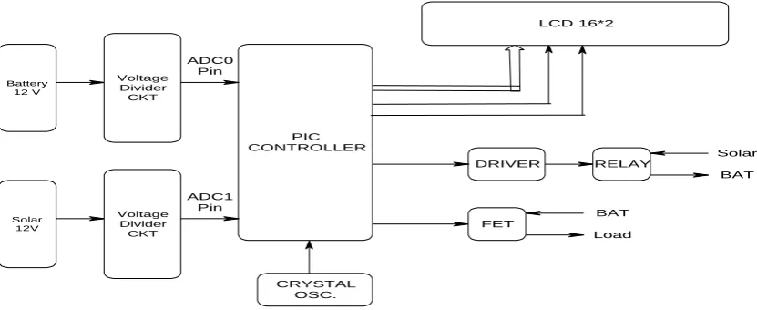
2.4 Block Diagram Of Solar Charge Controller Circuit:
CRYSTAL OSC. PIC CONTROLLER LCD 16*2 Battery 12 V ADC0 Pin Voltage Divider CKT Voltage Divider CKT Solar 12V ADC1 Pin BAT Load FET BAT Solar DRIVER RELAY
Fig. 4: Block Diagram Of Solar Charge Contoller
A micro controller is used for presages voltage maintaining for battery to solar cutout and battery to load circuit. A PIC16F72 Programmable interface Controller is used for small size and inbuilt analog inputs to determine voltage level of battery and solar cell, only two of that in circuit relay are used for connecting and disconnecting battery to solar cell. It is driven from transistor and MOSFET is used for load to battery connection. Maximum charge of battery is 12.8 V and minimum cutout is 10.8 V so first step is that to determine voltages. It is done from a dc input of controller. 1st channel is for solar voltage and 2nd for battery voltage but its voltage is high that is 12V or onward so a resister in series is connected for down voltages and is calibrated in the programming of controller for protection of a dc input.Zener is connected Lcd 16*2 is connected for displaying voltage level of battery and solar. It is working on program of controller and power supply. All components are designed from battery supply and 7805 regulator for 5V. For reverse voltage protection a small diode is connected in series of supply voltage.[11-12]
3.1 Description of PIC 16F72:
The microcontroller used is a reasonably fast PIC, chosen for its sufficient number of I/O pins, flash reprogram ability, and application memory. The 16F72 may be swapped with any pin compatible PIC, although the code may need to be updated.
Operating Frequency is 0-20 MHz Only 35 no. of Instructions. 5- Channel 8-bit ADC. 2 K Flash program Memory. 8 Interrupts.
Power Saving Sleep Mode. Selectable Oscillator Option.
It has 28 pin out & High Sink/source Current 25mA. Low power, high speed CMOS FLASH technology.
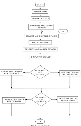
4.1) Flow Chart:
DISPLAY IT ON LCD DISPLAY IT ON LCD SELECT 1 st CHANNEL OF ADC
INITIALIZE ADC OF PIC Controller
A
SELECT 2 st CHANNEL OF ADC Initialize LCD 16*2
Initialize Ports START
CLEAR PORT PIN OF FET OF LOAD
SET PORT PIN OF FET OF LOAD
A IS 1st ADC
O/P = > 10.8 V CLEAR PORT PIN OF
RLY OF SOLER SET PORT PIN OF
RLY OF SOLER IS 1st ADC
O/P =>12.8V
Fig. 5:- Flow Chart
4.2) Bottom view of PCB
5.1 Advantages:
Circuit has very high precision even in milli volts. Lower and higher cut-off voltages can be changed with the help of modes. Switches are provided as additional feature. A simple IN4007 diode at the I/P provides the reverse current protection to the circuit. It has overload protection built in, usually with a push-button reset. LCD display is provided as an additional feature. LED’s are used to display the Status of various functions being performed. In circuit resistors are used instead of driving circuit to drive MOSFET, this reduces cost of circuit. It contains a large width bus lines which are able to carry high current of value 5A.It contains mostly digital components & no analog components which tends to increase the accuracy & thermal stability. It has reduced size so it is easy to install in rural areasThese indicators are important and useful.
6.1 Limitations:
The ideal set points of charge controller depend on the battery. As we are using sustainable electrical sources, like solar panel it will require some more time to charge battery Cloudy environment create difficulty to charge battery through solar panel.
7.1 Applications:
A charge controller for a wind-electric or hydro-electric charging system must protect batteries from overcharge, just like a PV controller. It is used for many lighted highway signs, eliminating the need for diesel generators. Telecommunications, oil companies, and highway safety equipment all rely on solar power for dependable, constant power, far from any power lines. It can also be used in Automobiles to increase their battery life. It can be also used as a supplement for the inverter to control battery charging .etc.
8.1Conclusions:
As the PV system is very advantageous & solar recourse is Unlimited the Government of Various Countries tried to take the use of such recourses but they faced many difficulties in actually implementing the technology. So a circuit which controls a battery charging is demanded by the government. If an analog circuit is designed it has many disadvantages such as cost & working problem. It has to reset whenever there is passage of low current through driving circuit of FET. As a result many complaints are received from different areas of country. Thus there is a need of some special circuit which can overcome the disadvantages of the analog circuit and must provide a high precision and accuracy with very low size & cost.
In order to overcome the above problem a circuit was designed which could fulfill the entire requirement with lower cost (<500/-) would be small in size. It can also be used in car batteries & for household purpose as a supplement to the inverter. In this way the circuit has real time application
The control of battery charging is so important that most manufacturers of high quality batteries (with warranties of five years or longer) specify the requirements for voltage regulation, low voltage disconnect and temperature compensation. When these limits are not respected, it is common for batteries to fail after less than one quarter of their normal life expectancy, regardless of their quality or their cost.A good charge controller is not expensive in relation to the total cost of a power system. Nor is it very mysterious.
Acknowledgement:
Authors are thankful to the Director of VNIT, Nagpur for providing the necessary facilities to carry out the research work and Dr. Nitin W. Ingole, Professor, Prof Ram Meghe Institute of Technology and Research, Badnera for the help render during preparation of manuscript.
References:
[1] R. Baharom, , S. A. Ramli and M. K. Hamzah; ; “Peripheral Interface Controller (PIC) Based
[2] Smart Low Power AC-DC Converter”, Symposium on Industrial Electronics and Applications SIEA 2010, Oct 3-5 2010,Penang,
Malaysia.
[3] Moschopoulos, G.; Jain, P.; “Single-phase single-stage powerfactor-corrected converter topologies”, EEE Transactions on Industrial
Electronics, Volume 52, Issue 1, Feb. 2005 Page(s):23 – 35.
[4] Huber, L.; Yungtaek Jang; Jovanovic, M.M.; “Performance Evaluation of Bridgeless PFC Boost Rectifiers”, IEEE Transactions on
Power Electronics, Volume 23, Issue 3, May 2008 Page(s):1381 – 1390.
[5] Salmon, J.C.; “Techniques for minimizing the input current distortion of current-controlled single-phase boost rectifiers”, IEEE
Transactions on Power Electronics, Volume 8, Issue 4, Oct. 1993 Page(s):509 – 520.
[6] F.Z. Peng, H. Akagi, ''A new approach to harmonics compensation in power system - A combine system of shunt passive and series
active filters'', IEE Transactions on Industry Application, Vol.26, No.6, Nov/Dec 1990.
[8] W.J.A. Teulings et al, "New maximum power point tracking system." Proc. of IEEE 24thAnnual Power Electronics Specialist Conference 1993, pp.833-838.
[9] R.C. Dorf,Electncal Engineering Handbook, CRC Press, 1993.
[10] T. Hiyama et ;d. “Evnluation of Neural Network Based Real Time Maximum Powei- Tracking Controller goes PV System”, IEEE
Transnctions on Energy Conversion, Vol. IO,N. 3, September 1995.
[11] M. G. Simoes and N. N. Franceschetti, "A RISC-microcontroller based Photovoltaic System for Illumination Apphcation," Proc. of
IEEEAPEC Conf, Vol. 2, pp. 1151 -1156, New Orleans, LA, USA, 2000.
[12] N. Khaehintung, and P. Sirisuk, "Implementation of Maximum Power Point Tracking Using Fuzzy Logic Controller for
Solar-Powered Light-Flasher Applications," Proc. of MWSCAS 2004 Conf, pp. 111-171-174, Hiroshima, Japan, 2004.
[13] N. Khaehintung, P. Sirisuk and W. Kurutach, "A novel ANFIS controller for maximum power point tracking in photovoltaic