1
M.Tech Scholar (Mechanical Engineering),
2Associate Professor
Nalanda Institute of Engineering & Technology (NIET), Siddharth Nagar, Guntur, (India)
ABSTRACT
The automobile engine connecting rod is a high volume production vital element. Every vehicle that uses an
internal combustion engine requires at least one connecting rod .From the viewpoint of functionality, connects
the rods must have the maximum possible rigidity at the less weight. The major stress induced in the connecting
rod is a combination of axial and bending stress in process. The axial stresses are caused due to cylinder gas
stress and the inertia force arising in account is due to reciprocal action (both tensile as well as compressed),
where as bowing stresses are occured due to the diffusive effects. The result of which is, the maximal stresses
are developed at the fillet section of the big and the small end.
I. INTRODUCTION TO CONNECTING ROD
The notational link between rods that function in internal combustion engines are exposed to high cyclic loads consists of influential tensile and abridge loads. They must be capable of transmitting axial tension and abridge loads, as well as assist bending stresses caused by the thrust and pull on the piston and by the centrifugal force of the rotating crankshaft. The Figure presents schematic illustrations of a connecting rod and its location and function in an engine
.
II. PROBLEM STATEMENT
Analysis of Connecting Rod
MATERIAL ALUMINUM ALLOY
Model > Geometry > Figure
Figure: 1 Geometry Model of Connecting Rod
Model > Geometry
Mesh
Model > Mesh > Figure
Figure: 2 Meshed Model of Connecting Rod
Figure: 3 Loading condition
Model (A4) > Static Structural (A5) > Loads
Model> Solution> Total Deformation > Figure
Figure: 4 Total Deformation on the connecting rod
Model> Solution> Equivalent Elastic Strain > Figure
Figure: 5 Equivalent Elastic Strain on the Connecting Rod
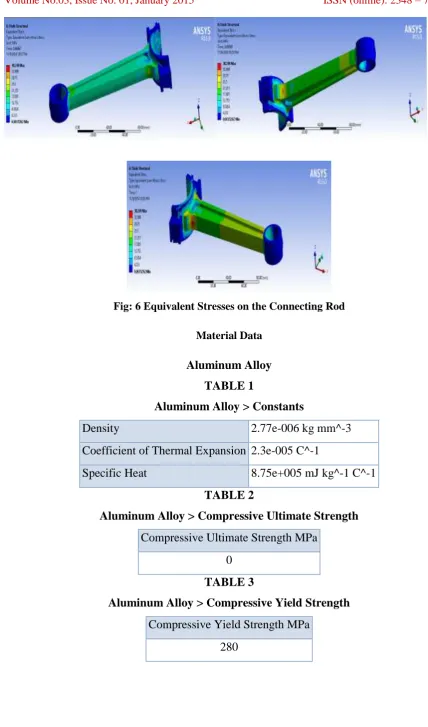
Fig: 6 Equivalent Stresses on the Connecting Rod
Material Data
Aluminum Alloy
TABLE 1
Aluminum Alloy > Constants
Density
2.77e-006 kg mm^-3
Coefficient of Thermal Expansion 2.3e-005 C^-1
Specific Heat
8.75e+005 mJ kg^-1 C^-1
TABLE 2
Aluminum Alloy > Compressive Ultimate Strength
Compressive Ultimate Strength MPa
0
TABLE 3
Aluminum Alloy > Compressive Yield Strength
Compressive Yield Strength MPa
Aluminum Alloy > Tensile Ultimate Strength
Tensile Ultimate Strength MPa
310
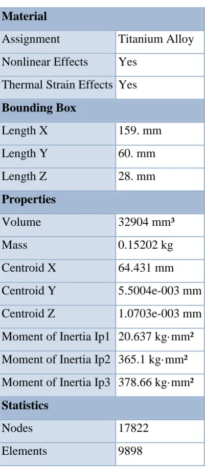
Case II: material Titanium Alloy
TABLE 6
Model> material
Material
Assignment
Titanium Alloy
Nonlinear Effects
Yes
Thermal Strain Effects Yes
Bounding Box
Length X
159. mm
Length Y
60. mm
Length Z
28. mm
Properties
Volume
32904 mm³
Mass
0.15202 kg
Centroid X
64.431 mm
Centroid Y
5.5004e-003 mm
Centroid Z
1.0703e-003 mm
Moment of Inertia Ip1 20.637 kg·mm²
Moment of Inertia Ip2 365.1 kg·mm²
Moment of Inertia Ip3 378.66 kg·mm²
Statistics
Nodes
17822
Temperature
0
C
Young's
Modulus
MPa
Poisson's
Ratio
Bulk
Modulus
MPa
Shear
Modulus
MPa
22
96000
0.36
1.1429e+005
35294
Model> Static Structural> Force
Loading Condition
Model > Static Structural> Loads
Definition
Type
Fixed
Support
Force
Suppressed No
Define By
Vector
Magnitude
3500. N
(ramped)
1000. N
(ramped)
Direction
Defined
Model> Static Structural> Solution> Total Deformation > Figure
Figure: 7 Total Deformation on the connecting rod
Model> Static Structural> Solution > Equivalent Elastic strain >Figur
Fig: 8 Equivalent Elastic Strain on the Connecting Rod
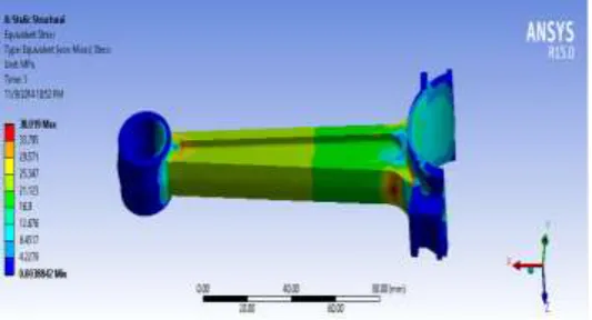
Model> Static Structural > Solution > Equivalent Stress > Figure
Figure: 9Equivalent Stress on the connecting rod
TABLE 7
Model > Static Structural> Solution > Results
Type
Total Deformation Equivalent Elastic Strain Equivalent (von-Mises) Stress
Results
Minimum 0. mm
5.4009e-008 mm/mm
3.8842e-003 MPa
Maximum 3.9983e-002 mm 3.9645e-004 mm/mm
38.019 MPa
Minimum Value Over Time
Minimum 0. mm
5.4009e-008 mm/mm
3.8842e-003 MPa
Maximum 0. mm
5.4009e-008 mm/mm
3.8842e-003 MPa
Maximum Value Over Time
Minimum 3.9983e-002 mm 3.9645e-004 mm/mm
38.019 MPa
Maximum 3.9983e-002 mm 3.9645e-004 mm/mm
38.019 MPa
Material Data
Titanium Alloy
III. CONCLUSION
In our project we have designed a connecting rod and modeled in 3D modeling software CRE2and then we analyze the connecting rod with different materials like Aluminum Alloy and Titanium Alloy with help of fem. In this Project we describe the stress distribution of the connecting rod by using FEA. The finite element analysis is performed by using computer aided design (CAD) software.
Material Equivalent (von-Mises) Stress Deformation Mass Titanium Alloy 38.019 MPa 3.9983e-002 mm 0.15202 kg Aluminum Alloy 38.249 MPa 5.4421e-002 mm 0.091145 kg
[2] Al-Hassan, A., Y. and D.R. Hill, Islamic Technology. 1994, New York:Cambridge University Press. [3] Hill, D.R., Islamic Science and Engineering. 1993, Edinburgh: EdinburghUniveristy Press.
[4] Gille, B., The Problems of Power and Mechanization, in A History of Technology and Invention, M. Daumas, Editor. 1969, Crown Publishers, Inc: New York. p.446-47.
[5] Gille, B., The Growth of Mechanization, in A History of Technology andInvention, M. Daumas, Editor. 1969, Crown Publishers Inc: New York. p. 42-45.
AUTHOR PROFILE
B. Krishna Reddy is currently pursuing M.Tech in the Department of Mechanical Engineering (CAD/CAM) from Nalanda Institute of Engineering & Technology (NIET), siddharth Nagar, Kantepudi(V), Sattenapalli (M), Guntur (D), Andhra Pradesh , Affiliated to JNTU-KAKINADA.