R E S E A R C H
Open Access
ADCNC-MAC: asynchronous duty cycle with
network-coding MAC protocol for
underwater acoustic sensor networks
Xiaoning Feng
1*, Zhuo Wang
2†, Xiulong Liu
1†and Jiajie Liu
1†Abstract
To reduce the energy cost of underwater acoustic sensor networks (UWSNs), the duty cycle (i.e., periodic wake-up and sleep) concept has been used in several medium access control (MAC) protocols. Although these protocols are energy efficient, they sacrifice bandwidth utilization, which leads to lower transmission rate. In order to solve this problem, asynchronous duty cycle with network-coding Asynchronous Duty Cycle with Network-Coding MAC (ADCNC-MAC) is proposed. It contains initialization of the MAC protocol phase and data transmission phase. In the first phase, we use an asynchronous duty cycle to find a rendezvous time for exchanging data. A strategy to select network coder nodes is presented to confirm the number of network coder nodes and distribution in the network coder layer. In the data transmission phase, the network coder nodes transmit using the proposed network-coding-based algorithm and a higher volume of packet will be transmitted to the Sink with the same number of transmissions. Simulation results show that ADCNC-MAC achieves higher power efficiency, improves packet delivery ratio (PDR), and network throughput.
Keywords:Underwater acoustic sensor networks (UWSNs); Medium access control (MAC); Duty cycle; Network coding
1 Introduction
Underwater acoustic sensor networks (UWSNs) enable a wide range of application, including environment monitoring, tactical surveillance, disaster warning, and many more. UWSNs employ acoustic communications [1–5]. Compared with radio transmissions in wireless sensor networks (WSNs), the challenges of acoustic transmissions include (1) long propagation delay: The propagation speed for an acoustic link is 1500 m/s, 2 × 10⁵times lower than the speed of a radio link. This means the propagation delay is 2 × 10⁵ times longer for an acoustic link. (2) Expensive transmitting power consumption: Power consumption for transmitting and receiving is similar in radio links. However, in acoustic links, the transmit power dominates and is typically 100 times more than the receive power. For example,
in the WHOI Micro-Modem [6], the transmit power is 10 W which is 125 times of the receive power (80 mW). (3) Lower available bandwidth: Influenced by harsh environment such as transmission loss, noise, and high propagation delay, the available band-width is limited and depends on both range and frequency.
Imperative and co-related research have shown en-ergy as the most decisive resource for any UWSNs; the demand for extended network lifetime motivates the design of energy-efficient medium access control (MAC) protocols [7]. Consequently, the periodic wake-up and sleep schedule (namely duty cycle) MAC is introduced to reduce energy consumption. In this technique, each sensor node has its own wake-up schedule. For example, with a 10 % duty cycle, a node has its state on only 10 % of the time, resulting in substantial energy savings. In the active state, a node is able to transmit or receive data, but in the sleeping state, the node completely turns off to save energy [8].
* Correspondence:[email protected] †Equal contributors
1
College of Computer Science and Technology, Harbin Engineering University, Harbin 150001, China
Full list of author information is available at the end of the article
So far, based on rendezvous selection between sender and receiver, duty cycle MAC protocols are mainly categorized into synchronous and asynchronous protocols. In a synchronous MAC [9], nodes in the same neighborhood are time-synchronized for simul-taneous wake-up at the beginning of a common cycle
and transmit their data. However, nodes’
simultan-eous wake-up in synchronous protocols results in higher collisions, and it is more difficult to imple-ment in UWSNs.
Conversely, in asynchronous protocols [10], nodes maintain their individual cycles randomly and allow nodes to operate independently. Such protocols typically employ low power listening, in which, prior to data transmission, a sender transmits a preamble to rendez-vous with the receiver [11]. When the receiver wakes up and detects the preamble, it stays awake to receive the data. These protocols achieve high energy efficiency and remove the synchronization overhead required in syn-chronous duty cycle approaches. However, duty cycle MAC protocols reduce bandwidth utilization and lead to a lower transmission rate.
The network-coding technique [12] improves the capacity of an information network with better utilization of bandwidth. In a multi-hop communica-tion with network coding, the intermediate nodes of a network can appropriately encode the incoming data packets before forwarding the coded packets to the next node. The network-coding technique also improves reliability of the network. In this work, the selection of network coder node strategy has been proposed; we use an asynchronous duty cycle to find a rendezvous time for exchanging data in order to reduce energy consumption, and network coder nodes use a network-coding-based communication paradigm to improve the bandwidth utilization and reliability of the network.
The major contributions of this work can be summa-rized as follows: (1) According to the application of an autonomous underwater vehicle (AUV) in a fixed area to collect data, we defined the corresponding network model. (2) A selection strategy of network coder nodes is introduced, in order to confirm the number of net-work coder nodes and distribution. (3) Asynchronous schedule selection is proposed to confirm a rendezvous time for each sender-receiver pair. (4) A network-coding-based algorithm is proposed to transmit data. (5) Simulations have been carried out to show the ef-ficacy of the proposed approach in terms of network throughput, packet delivery ratio (PDR), and energy consumption.
The rest of this paper is organized as follows: Section 2 presents a background study on existing UWSNs of MAC protocols, Section 3 introduces detailed protocol
operations, Section 4 presents performance evaluations by simulation efforts and comparisons, and Section 5 provides our conclusions.
2 Related work
The recent design of high transmission rate and energy-efficient MAC protocols concentrated on terrestrial sensor networks [13] and the techniques that have been developed are not suitable for the challenging underwater acoustic communication medium that experiences a very large propagation delay of 1 s over 1.5 km. In past acoustic network deployments, frequency-division multiple access (FDMA) was used, e.g., in the 1998–1999 SeaWeb [14] and in [15], but it was found to be restrictive and inefficient in terms of bandwidth utilization. SeaWeb 2000 favored a car-rier sense multiple access/collision avoidance (CSMA/CA) solution with ready-to-send/clear-to-send (RTS/CTS) ex-change; however, the problem with the application of handshaking protocols to UWSN is the energy consump-tion overhead caused by theRTS/CTSpackets [14].
A recent underwater networking solution [16] pro-posed by Xie and Gibson seeks to achieve predictable end-to-end delays in the network by the use of a base station that computes routes for all underwater
sensors. This obviates the RTS/CTS exchange and
significantly reduces both the propagation delay and jitter along each route; however, there are issues re-garding the scalability of this centralized solution to a large number of nodes.
The underwater acoustic network MAC (UWAN-MAC) [11] overcomes the energy consumption overhead problem with the “sleep mode” during transmission. In UWAN-MAC,SYNCbeacons are transmitted by the sender; if the receiver detects theSYNC, it knows when to send data in the next cycle and then it goes to sleep. Hence, UWAN-MAC reduces the energy consumption through periodic wake-up. However, it lowers the transmission rate due to the duty cycle. Additionally, UWAN-MAC is a synchron-ous MAC protocol, it is difficult to synchronize among nodes in the network.
over the middle path. Hence, two groups of packets can be transmitted over three paths reliably. MPNC-MAC provided higher throughput and reliability of data transmission. However, the MPNC-MAC proto-col only applies to the sparse network, and it wastes energy consumption due to idle listening.
3 ADCNC-MAC design
3.1 Network model
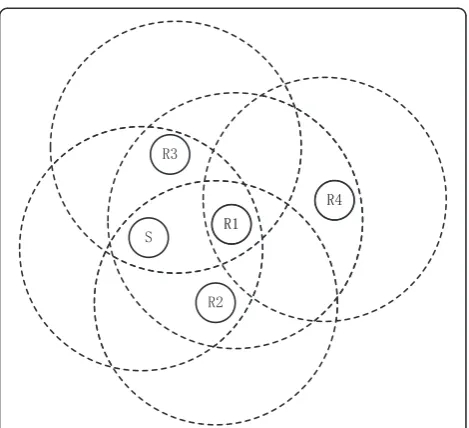
In UWSNs, sensor nodes are randomly deployed in some fixed area to collect data, and we use AUVs or underwater gliders to receive data which the sensor nodes collected. According to the application above, we defined a UWSN network model as shown in Fig. 1.
The model is considered with N sensor nodes
scat-tered uniformly in an area, and all theN sensor nodes are duty cycled. The nodes are named based on their roles in the network as shown in Fig. 1. The nodes are differentiated into three groups: relay sensor, network coder sensor, and the Sink. The relay sensor nodes generate data and transmit the generated data to the Sink. The network coder sensor nodes encode the raw native data which comes from the relay nodes before transmission. The Sink receive data and decode the data from network coder nodes. In the area, the relay nodes can communicate with the Sink using a multi-hop communication. However, the network coder nodes use a single hop to communicate with the Sink. The nodes in the range of the Sink are defined as the network-coding layer, and all the network coder nodes are in the layer.
3.2 Initialization of the MAC protocol
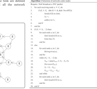
The number of network coder nodes is an important parameter in the asynchronous duty cycle with network-coding MAC (ADCNC-MAC) protocol; it will reduce the decoding rate of the Sink if the number of network coder nodes is too big. To ensure proper decoding of the network-coded packets at the Sink, not more than 50 % of network coder nodes in the network-coding layer are needed [19]. Algorithm 1 represents the core operations of the selection of network coder nodes. Cn represents the nodes in the network-coding layer,
and Nn is the number of nodes in the
network-coding layer. In the same way, Cs designs the nodes that satisfy the conditions of the proposed algorithm,
and Ns is the number of nodes that satisfy the
conditions.
The Sink broadcasts a selection of network coding
node (SNC) packet to its neighbor nodes. The SNC
packet contains the threshold of energy (En) and the threshold of buffer (Bn). For each neighbor node, it checks its own energy and buffer to determine whether it is larger than the threshold or not. Mean-while, each node also checks its routing table (CheckRT()) to find if more than one node transmits data to it. The nodes will send acknowledgement (ACK) packets to the sink if they satisfy the above conditions. Each of the ACK consists of its node’s geographical position information [20].
The Sink counts the receivedACKpackets. IfNs≦Nn/2, the sink confirms them as network coder nodes. If
not, we divide the area of the Sink into i parts
equally. As the Sink knows each of the sent ACK
node’s geographical position information, we can check the number of nodes in each area (BelongArea(ni)). After that, we select the most nodes of area (Nimax) to decrease in every cycle. We reduce min (Nimax/2, Ns−Nn/2) until Ns=Nn/2. Then, the Sink announces the remaining nodes as network coder nodes. Finally, each node in the network-coding layer knows its role.
3.2.1 Asynchronous schedule selection
After the selection of the network coder node phase is complete, we could determine an asynchronous schedule for each sender-receiver pair. In Fig. 2, the direction of data transmission isS→R. NodeSbroadcasts a determine each of transmission (DET) packet (the shaded rectangle in the figure) at the beginning of its cycle period and then goes to sleep by turning off its transceiver circuits to save energy. ThisDETpacket announces nodeS’s transmission cycle period“T.”Assume that nodeRis located near node S. TheRmonitors the channel forDETpacket. (The white rectangles in the figure indicate node R’s receptions of node S’s DET packets.) After receiving the DET packet,
node R decodes the length of the transmission cycle
period“T”from this message thenRknows when to wake up to monitorSafter this period. In this method, all nodes can initialize their transmission/listen schedules.
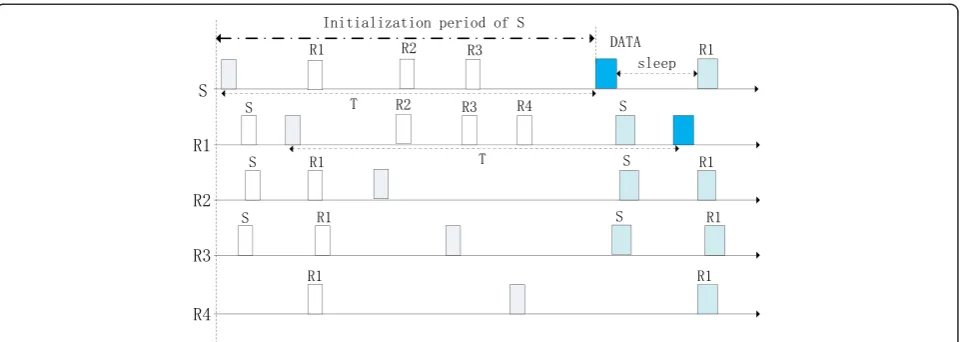
We use the network in Fig. 3 as an example network configuration throughout this paper. In this figure, each node sets its transmission range and each circle indicates the transmission range of the node at its center. For this given network topology, the broadcasting of DETpackets in the initialization period is illustrated in Fig. 4. In this fig-ure, each node broadcasts its DET packet and remains awake until the beginning of the next cycle to receive its neighbors’DETpackets. NodeSbroadcasts itsDETpacket first. Then, node S’s neighbors receive the DET packet during initialization which allows them to schedule
their wake-up times. Node S will also schedule
par-ticular wake-up times as shown in this figure for its neighbor nodes R1, R2, and R3 after it hears their schedules during this initialization period.
3.3 Data transmission after initialization
3.3.1 Definition of packet structure
After the initialization phase, each node has its role in the network model and knows when to wake up again to receive data from its neighbors. Starting with the next cycle, nodes follow their established schedules in the initialization period and begin send-ing data. Figure 5 shows the structure of the data transmission packet. The transmission duration has two distinct parts: “CF” and “DATA Tx.” The “DATA Tx” corresponds to the part where actual data is be-ing sent. “CF” is a control frame; it contains each node’s cycle period “Tx” which may be different from the one (T) in the initialization period.
Figure 6 shows that during the data transmission
phase, S has the option to change its current cycle
period by using the CF message. Its neighbor R can
decode the modified CF message and change wake-up
times for that node, starting with the next cycle. It can avoid a time-consuming re-initialization by keeping aCF message in the packet.
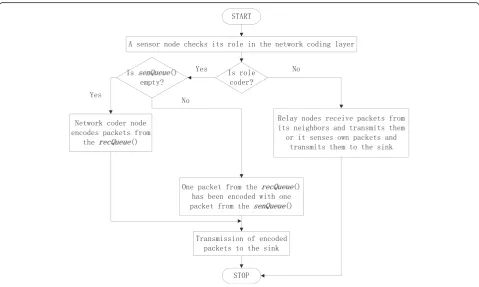
3.3.2 Data transmission of nodes
Whenever a node wakes up in the network-coding layer and receives a packet, it checks its role (refer Fig. 7). If it is a relay sensor node, it simply forwards the re-ceived data, whereas, network coder nodes follow the Fig. 2Initialization phase for the nodes
Algorithm 2 to process packets. Each node in the network-coding layer maintains a received queue (recQueue()) and a sensed queue (senQueue()). On
receiving a packet Pi, a node puts the packet in
recQueue(Pi). If the packet is already processed by the node, then it is discarded, otherwise checks sen-Queue() to determine whether it is empty or not. If
it is not empty, pick a packet Pj from senQueue()
and coded with Pi, otherwise pick next packet Pi + 1 from recQueue() and coded with Pi. On successfully creating an encoding packet, the node transmits the coded packet to the Sink. The processed packet is inserted into the forwarding set ForwardSet() which stores the forwarded packets. This helps in restricting further redundant transmissions.
Decoding of packets at the Sink: The Sink node re-ceives native packets from the simple relay nodes and coded packets from the network coder nodes. In COPE [19], the intermediate nodes encode and de-code packets. Unlike COPE, the decoding procedure is performed only at the Sink which processes all the gathered data in UWSNs. The Sink maintains a pool of packets, in which it stores each received native packet. When the Sink receives an encoded packet consisting of two native packets, the Sink retrieves the corresponding native packets one by one from
the pool of packets. The Sink XORs the two native
packets with the received coded packet to retrieve the missing packet which is totally lost or received with error at the Sink.
The above is best illustrated with an example in Fig. 8. In Fig. 8a, network-coding nodeNhas three packets in its recQueue()P1,P2, andP3. Relay nodeRhas one packet in its putout queueP1. The table in Fig. 8b shows the next hop of each node. NodesNandRtransmit packets to S. In Fig. 8c, node N follows the Algorithm 2 to encode packets. It can process two coded packets C1=P1⊕P2 and C2=P2⊕P3. Node R relays P1 to the S. Node S Fig. 5Transmission packet structure
decodes P2 and P3 in a single transmission. The
above example shows that when packet P2 orP3has
an error, nodeScan recover from network-coding packets.
4 Performance evaluations
The simulation of ADCNC-MAC is extensively per-formed in ns-3 [21], the performance of
ADCNC-MAC is analyzed in the 5 km×5 km×5 km area,
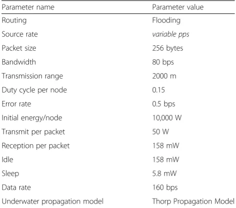
and all senor nodes are randomly deployed in it. Ex-periments are done for 10 times in each scenario to acquire the average value as results. Table 1 provides the details concerning the ADCNC-MAC simulation parameters; the majority of them have been extracted from the ns-3 of the uan module (underwater acous-tic network) [21]. This section presents two parts;
the first part presents performance analysis of the proposed algorithm, and the second part presents performance analysis of ADCNC-MAC. To gather
knowledge on the ADCNC-MAC performance,
UWAN-MAC and MPNC-MAC protocols are imple-mented in the same simulation environment and compared with it.
4.1 Performance analysis of the proposed algorithm
In order to demonstrate the effectiveness of the selection of the network coder node algorithm, we use three kinds of cases to compare. All of the cases are based on ADCNC-MAC, and only the number of network coder nodes in the network-coding layer is different. As we observe in Fig. 9, case 1 represents using the selection of network coder node algorithm. Case 2 represents no net-work coder nodes in the netnet-work-coding layer, and case 3 represents that all nodes in the network-coding layer are network coder nodes.
Figure 9a shows the relationship between the source data rate and throughput in different cases. It shows that the throughput performance of case 1 is better than case 2 and case 3, since case 1 uses the proposed al-gorithm which improves the Sink’s decoding rate and then improves the throughput. Case 3 leads that the Sink cannot decode when data transmits and reduces
Fig. 7Functionalities of the sensor nodes in the network-coding layer Fig. 6Modification of the cycle period during the data
the throughput of the network. Case 2 has no net-work coder nodes in the netnet-work-coding layer; its performance is better than Case 3.
Figure 9b shows the relationship between the source data rate and PDR in the different cases. It shows that the throughput performance of case 1 is better than case 2 and case 3; since case 1 has the highest decoding rate of the Sink, it can improve re-ception of data packets at the Sink. As source data rate increases, more and more collisions lead to lower PDR of the three cases. From Fig. 9, it can be seen that the proposed selection algorithm is strong
enough most of the time resulting in improved PDR and throughput.
4.2 Performance analysis of ADCNC-MAC
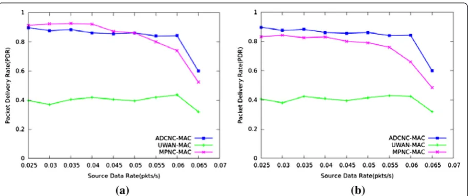
Figure 10 individually describes in different nodes the density, the relationship between the successful PDR, and the source data rate of protocols. Figure 10a shows when the nodes’ density is in 0.25/(km)3~0.5/(km)3, UWAN-MAC gets the lowest performance as it is not using the network-coding technique. MPNC-MAC gets the best PDR when the source data rate is less than 0.05 pkt/s. However, ADCNC-MAC gets better than MPNC-MAC when the source data rate is more than 0.05 pkt/s. As MPNC-MAC sends data in three disjoint paths, more data collisions lead to lower PDR as source data rate increases. Figure 10b shows when the nodes’
density is more than 0.5/(km)3, ADCNC-MAC gets
the best performance as the nodes’ density increases, while MPNC-MAC gets lower PDR due to data collisions.
Figure 11 shows in different nodes the density, the relationship between throughput, and the source data rate of protocols. It can be seen that UWAN-MAC gets the lowest throughput as it is not using network coding. While the source data rate is less
than 0.055 pkt/s, MPNC-MAC is better than
ADCNC-MAC. However, ADCNC-MAC is better than MPNC-MAC when the source data rate is more than 0.055 pkt/s. As the source data rate increases, more data collisions lead to MPNC-MAC having a lower throughput.
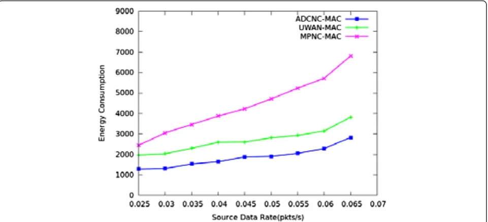
In Fig. 12, MPNC-MAC suffers greater energy con-sumption due to idle listening and coding packets of
Table 1Simulation parameters Duty cycle per node 0.15 Error rate 0.5 bps Initial energy/node 10,000 W Transmit per packet 50 W Reception per packet 158 mW
Idle 158 mW
Sleep 5.8 mW Data rate 160 bps
Underwater propagation model Thorp Propagation Model
(a)
(b)
(c)
all nodes. ADCNC-MAC and UWAN-MAC maintain low energy consumption at a low rate due to using a duty cycle technique to save energy consumption. However, ADCNC-MAC has lower energy consump-tion than UWAN-MAC as network coding can fuse packets. It can reduce the number of sending packets and save more energy. As the source data rate in-creases, the three protocols of the energy consumption also increase for idle listening and collision-related
retransmission. From Figs. 10, 11, and 12, the
performance of ADCNC-MAC is better than that of MPNC-MAC and UWAN-MAC as a whole.
5 Conclusions
In this paper, we have proposed an innovative asyn-chronously scheduled duty cycle with network-coding MAC protocol for UWSNs. Unlike previous MAC pro-tocols, ADCNC-MAC considers energy consumption, throughput, and PDR. In ADCNC-MAC, it uses a selec-tion of network coder node algorithm to select proper
Fig. 10The relationship between PDR and source data rate of protocols. (a) The nodes density in 0.25/(km)3 ~ 0.5/(km)3, (b) The nodes density more than 0.5/(km)3
network coder nodes before data transmission. In the data transmission phase, network coder nodes use a network-coding-based algorithm to code packets before transmitting them. This can make the Sink receive ap-proximately 50 % more data. Hence, it can significantly improve the PDR and throughput. Meanwhile,
ADCNC-MAC using an asynchronously scheduled duty cycle achieves a better energy consumption performance. The simulation results show that compared with MPNC-MAC and UWAN-MPNC-MAC, ADCNC-MPNC-MAC achieves rela-tively lower energy consumption with the higher reliabil-ity of data transmission.
Competing interests
The authors declare that they have no competing interests.
Author details
1College of Computer Science and Technology, Harbin Engineering
University, Harbin 150001, China.2College of Shipbuilding Engineering, Harbin Engineering University, Harbin 150001, China.
Received: 5 February 2015 Accepted: 7 August 2015
References
1. G Acar, A Adams, ACMENet: an underwater acoustic sensor network protocol for real-time environmental monitoring in coastal areas. Radar, Sonar and Navigation, IEE Proc.153(4), 365–380 (2006)
2. L Freitag and M Stojanovic,“Acoustic communications for regional undersea observatories,”Proceedings of Oceanology International, London, UK 2002
3. IF Akyildiz, D Pompili, T Melodia, Challenges for efficient communication in underwater acoustic sensor networks. SIGBED Rev.1(2), 3–8 (2004) 4. JH Cui, J Kong, M Gerla, and S Zhou,“Challenges: building scalable mobile
underwater wireless sensor networks for aquatic applications,”IEEE Network, Special Issue on Wireless Sensor Networking (NY, USA, 2006) pp. 12–18 5. J Heidemann, W Ye, J Wills, A Syed, and Y Li,“Research challenges and
applications for underwater sensor networking,”(IEEE WCNC, NY, USA, 2006) 6. L Freitag, M Grund, S Singh, J Partan, P Koski and K Ball, The WHOI
Micro-Modem: an acoustic communications and navigation system for multiple platforms. (In IEEE Oceans, Washington, DC, Sep. 2005) 7. Y Sun, O Gurewitz, DB Johnson, Ri-mac: a receiver initiated asynchronous
duty cycle mac protocol for dynamic traffic loads in wireless sensor networks, inSenSys’08: proceedings of the 6th ACM conference on Embedded network sensor systems(ACM, New York, NY, USA, 2008), pp. 1–14 8. Joseph Polastre, Jason Hill, and David Culler. Versatile low power media
access for wireless sensor networks. In Proceedings of the Second International Conference On Embedded Networked Sensor Systems (SenSys, NY, USA 2004), pages 95–107
9. W Ye, J Heidemann, D Estrin, Medium access control with coordinated adaptive sleeping for wireless sensor networks. IEEE/ACM Trans Netw
12(3), 493–506 (2004)
10. M Obaidur Rahman, A Muhammad Mahbub, M Muhammad Mostafa, S Choong, nW-MAC: multiple wake-up provisioning in asynchronously scheduled duty cycle MAC protocol for wireless sensor networks. Ann Telecommun.66, 567–582 (2011)
11. MK Park, V Rodoplu, UWAN-MAC: an energy-efficient MAC protocol for underwater acoustic wireless sensor networks. (IEEE Journal of Oceanic Engineering, Washington DC, VOL. 32, NO. 3, JULY 2007)
12. R Ahlswede, N Cai, SYR Li, R Yeung, Network information flow. IEEE Trans Inf Theory.46(4), 1204–1216 (2000)
13. W Ye, J Heidemann, D Estrin, Medium access control with coordinated adaptive sleeping for wireless sensor networks. IEEE/ACM Trans Networking.
12(3), 493–506 (2004)
14. J Rice, B Creber, C Fletcher, P Baxley, K Rogers, K McDonald, D Rees, M Wolf, S Merriam, R Mehio, J Proakis, K Scussel, D Porta, J Baker, J Hardiman, D Green, Evolution of Seaweb underwater acoustic networking. in Proc MTS/IEEE OCEANS.3, 2007–2017 (2000)
15. A Benson, J Proakis, M Stojanovic, Towards robust adaptive acoustic communications. in Proc MTS/IEEE OCEANS.2, 1243–1284 (2000) 16. G Xie, J Gibson,A networking protocol for underwater acoustic networks[R]
(Naval Postgrad, School Monterey CA Dept Of Computer Science, 2000) 17. G Zheng, B Wang, P Xie, W Zeng, JH Cui, Efficient error recovery with network
coding in underwater sensor networks. Ad Hoc Netw.7(4), 791–802 (2009) 18. S Cai, Z Gao, DS Yang, A network coding based protocol for reliable data
transfer in underwater acoustic sensor. Ad Hoc Netw.11, 1603–1609 (2013) 19. S Katti, H Rahul, W Hu, D Katabi, M Medard, J Crowcroft, XORs in the air:
practical wireless network coding. IEEE Trans Networking.16, 497–510 (2008)
20. Z Zhou, J Cui, S Zhou,“Localization for Large-Scale Underwater Sensor Networks [C].”Proceedings of IFIP Networking(Springer, Atlanta, Georgia, USA, 2007)
21. The Network Simulator–ns-3, <http://www.nsnam.org>. 2014-06-15
Submit your manuscript to a
journal and benefi t from:
7Convenient online submission 7Rigorous peer review
7Immediate publication on acceptance 7Open access: articles freely available online 7High visibility within the fi eld
7Retaining the copyright to your article