ISSN(Online): 2319-8753 ISSN (Print): 2347-6710
I
nternational
J
ournal of
I
nnovative
R
esearch in
S
cience,
E
ngineering and
T
echnology
(An ISO 3297: 2007 Certified Organization)
Website: www.ijirset.com
Vol. 6, Issue 7, July 2017
Power Quality Improvement of Renewable
Power Generation System Using Robust
Active Power Filter
Rupesh R. Wankar 1, S. S. Dhamse 2
P.G. Student, Department of Electrical Engineering, Government College of Engineering, Aurangabad, MH, India1
Associate Professor, Department of Electrical Engineering, Government College of Engineering, Aurangabad,
MH, India2
ABSTRACT: In this modern world use of non-linear load is increases rapidly. Every daily need equipment use of non-linear load is existence. Non-linear loads affect the power quality of the power systems. An active power filter executes with four- leg voltage source inverter (4L-VSI) is demonstrated. This system also mitigates unbalance current generated by non-linear load as well as allows the current harmonic components compensation. A simple mathematical model of active power filter presented with a prediction control algorithm with derivation of power system impedance. The performance of active filter compensation technique presented here with the simulation results.
KEYWORDS: Power Quality, Active Power Filter, Current Control, Current Compensation, Harmonics, Predictive Control, Non-linear load, Four-leg Converter
I. INTRODUCTION
Today’s generation people adopt a renewable power generation system for their domestic and industrial use. In villages popularity of micro grids are also increases rapidly [1]. If use of more renewable power it means that it get affects the power quality due to the nature of its non-linearity, since high –power static PWM converter is must be connected to the wind generators and solar power plants with respect to the grid [2]-[3]. A voltage and current distortion will occur in the power system due to the non-uniform nature of renewable power generation systems also directly affects the voltage regulation of the respective power system. These new challenges in the power systems need a proper compensation technique for the stable operation of distribution system. Due to development of modern industry more and more non-linear loads are connected due to which harmonic pollution is generated.
In this paper prediction control algorithm is designed and implement. Traditionally PI controller is specially designed for the linear model. Prediction current control method quickly spring up the current reference signal with maintaining consistent DC voltage and functioning awkwardly on transitory as well as typical operating surrounding. Mathematical model of three-phase four-leg voltage-source inverter (4L-VSI) is presented in this paper with prediction control method [4]-[6].Principle procedure along with the modeling operation of preferred current reference generator with complete confession implemented in active power filter is presented. Finally, in the simulation active power filter performance with effective current compensation and control method demonstrated [7].
II. PROPOSED SYSTEM DESCRIPTION
ISSN(Online): 2319-8753 ISSN (Print): 2347-6710
I
nternational
J
ournal of
I
nnovative
R
esearch in
S
cience,
E
ngineering and
T
echnology
(An ISO 3297: 2007 Certified Organization)
Website: www.ijirset.com
Vol. 6, Issue 7, July 2017
phase or three phase, linear or non-linear and, balanced or unbalanced [8]-[9]. Solar power generation is typically used to generate power. An active filter is connected in between the power distribution system and various types of loads.
Fig.1. Proposed systems block diagram
III.FOUR –LEG INVERTER MODEL
Fig.2. shows the structure of active power filter executed in proposed system. In between distribution point and the consumer premises a shunt active power filter is connected with 4L-VSI topology to compensation of current harmonics and current unbalance. Active power filter is a composition of four-leg PWM inverter, electrolyte capacitor and the first-order output ripple filter. In the circuit clearly exposed power system equivalent impedance Zs, converter
output ripple filter impedance Zf and load impedance ZL.
Fig.2. Equivalent circuit diagram of the proposed shunt active power filter
ISSN(Online): 2319-8753 ISSN (Print): 2347-6710
I
nternational
J
ournal of
I
nnovative
R
esearch in
S
cience,
E
ngineering and
T
echnology
(An ISO 3297: 2007 Certified Organization)
Website: www.ijirset.com
Vol. 6, Issue 7, July 2017
Fig.3. Four-leg PWM- VSI topology
The fourth leg of the converter raises switching states from 8 to 16, with additional developing current control affability and output voltage quality and it is suitable for the compensation of current unbalance [10].
Consider x be the any leg of the inverter to attain the voltage of any leg obtained from the neutral point (n) in the terms of switching states can be as follows,
xn x n dc
v
s
S
V
(1)x = u,v,w,n (voltage in any leg of the converter)
From the equivalent circuit diagram shown in fig.3
dt
di
L
i
R
V
V
o
xn
eq o
eq o(2)
Where,
Req = Rf and Leq = Ls + Lf
Req and Leq are the output parameter of the active filter indicate in terms of respect to the output terminal Zeq as
thevenins impedance
s L f s f
L s
eq
Z
Z
Z
Z
Z
Z
Z
Z
(3)
For this converter model, it is conclude that ZL>>Zs, by neglecting the equivalent impedance resistive part. Series
connection of ripple filter impedance Zf and combination of parallel adjustment between Zs and ZL we can resolve
thevenins equivalent impedance.
IV.DIGITAL PREDICTIVE CURRENT CONTROL SCHEME
ISSN(Online): 2319-8753 ISSN (Print): 2347-6710
I
nternational
J
ournal of
I
nnovative
R
esearch in
S
cience,
E
ngineering and
T
echnology
(An ISO 3297: 2007 Certified Organization)
Website: www.ijirset.com
Vol. 6, Issue 7, July 2017
assembles and implements this information for further operation to select the most favorable switching states and this is efficiently applied to the 4L-VSI. This control algorithm is predicted and studies the future behavior. Fig.4. shows the implementation of this control scheme in three main blocks. It generates a current required to active power filter operation for compensation.
*
o
i
1
k o
i
k1g
Fig.4. Block diagram of digital predictive current control scheme
(A) Current Reference Generator: In this case, system voltages, load currents and the dc-voltage of the four leg- voltage source inverter are measures and calculated from the signal neutral output current and neutral load current. This block construct and designed to development of the required current reference that is apply for undesirable load current components compensation.
(B) Prediction Model: Output converter current is predicted by this converter model. In this scheme the controller performs in discrete time domain, both the system model and the controller is expressed in a terms of discrete time rule [11]. A recursive matrix equation is applied to this prediction system to know the discrete time domain. At kTs we have to know the converter switching states and variable to be controlled at the given sampling time. At any instant [k+1]Ts the next states will be desirable the future behavior prediction and forecasting of the converter operation.
Because of the first-order description of the state equations that shows and presents in model (1)-(2), this paper shows a enough and accurate first order resemblance model has been considered.
t s x
T
k
x
k
x
d
d
[
1
]
[
]
(4)
s o o
t io
T
k
i
k
i
d
K
d
(
)
[
1
]
[
]
k
i
k
i
dt
K
d
T
io o os
1
)
(
1
)
(
k
i
k
i
dt
K
d
T
s io o o(5) From equation (2) rewritten as,
dt
di
L
i
R
V
ISSN(Online): 2319-8753 ISSN (Print): 2347-6710
I
nternational
J
ournal of
I
nnovative
R
esearch in
S
cience,
E
ngineering and
T
echnology
(An ISO 3297: 2007 Certified Organization)
Website: www.ijirset.com
Vol. 6, Issue 7, July 2017
eq io o xn ioL
k
R
k
V
k
V
dt
k
d
(6)
From (5) and (6) the 16 achievable output current forecasted values will be obtained as,
eq s eq o xn eq s oL
T
R
k
v
k
v
L
T
k
I
[
1
]
(
[
]
[
])
1
(7)
The 4L-VSI converter output voltage Vxn and the input voltage value Vo are required to forecast the respective output
current io at the instant (k+1) as shown in equation (7). This algorithm will calculate all Predicted 16 values associated
with all the combination that can achieve the state variable. While the elimination of current harmonics, current unbalance in the system prediction current control algorithm precisely predict the future behavior of the system model and do implementation of current compensation very smartly.
(C) Cost Function Optimization: In the power converter application our robust method is predictive control algorithm. To obtain the 16 possible optimal switching states and this values obtained for the Io[k+1]. By use of cost function g
obtained 16 possible values compared with the reference signal, as per following mathematical model:
2 *
[
1
]
[
1
])
(
]
1
[
k
i
k
i
k
g
ou ou* 2 2 * 2 *
])
1
[
]
1
[
(
])
1
[
]
1
[
(
])
1
[
]
1
[
(
k
i
k
i
k
i
k
i
k
i
k
i
on on ow ow ov ov (8)g = 0 condition satisfied when the output current (io) of the converter model is equivalent to the respective reference
current (io*). To minimize the cost function voltage vector VxN is preferred and it will employ and apply to the next
sampling condition. The minimum amount of cost function g is taken into explanation and select from the 16 possible function values all along each switching states. During the operation of converter in the k+1 state the algorithm preferred the applicable switching state and it creates the appropriate minimal value.
V. CURRENT REFERENCE GENERATION
Active power filter current reference signal is obtained by the dq-based current reference generator scheme. For fast and rapid specific signal tracking proficiency this scheme will execute very effective work. Voltage fluctuation is neglected and avoid by this characteristic for improvement of better compensation performance [12]. In fig.5 it is clearly mentioned that from load current obtained the corresponding current reference signal.
Current reference generation technique calculates and identifies the current reference signal useful for the current requirement of converter for the effective compensation to the current harmonics and current imbalance. The relationship between active power filter apparent power demand with respect to the load is determined by the displacement power factor (sinᶲ(L)) and the maximum total harmonic distortion of the load as shown in following
equation
( )2
2 ) ( ) (
1
sin
L L L L APFTHD
THD
S
S
(9)ISSN(Online): 2319-8753 ISSN (Print): 2347-6710
I
nternational
J
ournal of
I
nnovative
R
esearch in
S
cience,
E
ngineering and
T
echnology
(An ISO 3297: 2007 Certified Organization)
Website: www.ijirset.com
Vol. 6, Issue 7, July 2017
acceptable value of reference current.
* o
i
dq 0 uvw dq dq * dc v dc v * di
* qi
i
**
i
i
dd
i
i
qi
i
( )~
iq iq
) sin(
) cos(
Fig.5. dq-based current reference generator block diagram
The dq-based reference generation system operation is rotating reference frame; that’s why, the obtained and measured current have been multiply to the sin (wt) and cos(wt) signals. By applying the dq-transformation, d current elements integrate and combined with the respective phase-to-neutral system voltage and q current component with phase-shifted by an angle 900. Main objective of synchronous reference frame (SRF) PLL to acquire the sin (wt) and cos(wt) synchronized reference signals [13]. Major problem of the power system is voltage is severely distorted to overcome this problem SRF-PLL is employed it generates a pure sinusoidal waveform. Elimination of tracking error is occurs, since SRF-PLL are employed to avoid and elimination phase voltage unbalance, harmonics components and off load conditions occurs due to the measurement error and the non-linear load.
w v u q diL
iL
iL
wt
wt
wt
wt
i
i
2 3 2 3 2 1 2 10
1
sin
cos
cos
sin
3
2
(10)Connection among the real currents iLx (t) (x=u,v,w) and the identified dq components (id and iq) presents clearly in
equation (10). To the generation of harmonic reference components –id a low-pass filter is hired to excerpt the dc
component of the phase – currents id. By appropriate phase shifting the comparable ac and dc component of iq with an
angle 1800 we get reactive reference components of the phase-currents. In order to control dc voltage constant conversion of inverter reference signal is needed with the help of this it is possible to maintain the dc voltage constant [12]-[13].
2 3 2 1 2 1 2 3 2 1 2 1 2 1 * **
1
0
3
2
ow ov oui
i
i
* * sin cos 0 cos sin 0 0 0 1 q d o i i i wt wt wt wt (11)ISSN(Online): 2319-8753 ISSN (Print): 2347-6710
I
nternational
J
ournal of
I
nnovative
R
esearch in
S
cience,
E
ngineering and
T
echnology
(An ISO 3297: 2007 Certified Organization)
Website: www.ijirset.com
Vol. 6, Issue 7, July 2017
and iq* are getting in three-phase system. The LPF cut of frequency used in this paper is 20Hz.
The phase currents with phase shifting by 1800 obtained in equation (12). This defines the current that flowing through the neutral of the load is compensating by to inject the same instantaneous value with the help of phase currents.
)
(
*
Lw Lv Lu
on
i
i
i
i
(12)
The dq-based current reference scheme is admit the operation of linear controller in the dc-voltage control loop implementation. This is the major advantage of this proposed reference generator scheme. In the operation and determining the dq-based reference generator scheme the second harmonic component is generated automatically under balance as well as transient operating conditions. This is negligible disadvantage of this control scheme.
Mathematical analysis of Total harmonic distortion (THD) obtained from,
1 2
1 2
o o or
I
I
I
THD
(13)
T
or
I
dt
T
I
0 2
1
(14)
Where, Ior total average RMS value and Io1 RMS value of fundamental component. After calculating the mathematical
analysis of total harmonic distortion this values verified with FFT analysis from the MATLAB/Simulink. A. DC- Voltage Control
C(s)
* dc
v
e
i
e G(s)v
dc+
Fig.6. Block diagram of DC voltage control
PI controller is used to control the dc-voltage converter this is classical controller. It is decisive issue in the manifestation before the cost function employed only for the current references. There is no disturbance effect of the slow dynamic response of the voltage in the electrolyte capacitor. It will not contain any effect to the current transient process; therefore PI controller always gives the simple, clean and robust option to the dc-voltage control.
For the minimum value of
) (
6vs rms the dc- voltage gives constant value as far as the active power captivated by the
converter fall down [13]. By adjusting the peak value of active power filter reference signal ie it will control the active
power consumed by the proposed converter. In fig.5 we seen that dc-voltage Vdc is measured and then it is compared
with the constant reference value Vdc*. With two gains in the systems, Kp and Ti both gains will decided by the dynamic
feedback requirement.
*
2
2
3
)
(
dc dc
s p
e dc
v
C
v
K
i
V
S
G
(15)
ISSN(Online): 2319-8753 ISSN (Print): 2347-6710
I
nternational
J
ournal of
I
nnovative
R
esearch in
S
cience,
E
ngineering and
T
echnology
(An ISO 3297: 2007 Certified Organization)
Website: www.ijirset.com
Vol. 6, Issue 7, July 2017
equation
s
T
K
s
C
i p
.
1
1
)
(
(16)
2 2
.
2
)
(
2
n n
a w
e dc
w
s
w
s
a
s
i
v
n
(17)
For the operation of this voltage control method damping factor =1 and natural angular speed Wn =100rad/sec are taken
to verify and obtain the with minimal voltage oscillation critically damped response. The respective integral time Ti
and gain Kp calculated as,
*
2
8
3
dc dc
i s p
v
C
T
v
K
(18)
i dc dc
s p n
T
v
C
v
K
w
*2
2
3
(19)
After calculating this respective value the dc- voltage control is obtained and dc-voltage control is also important parameter of this process while maintaining the input of converter. Not maintained operation of DC-voltage control it is dangerous for system representation and it may be collapse the whole system due to absence of proper voltage control in the system.
VI.SIMULATION RESULTS
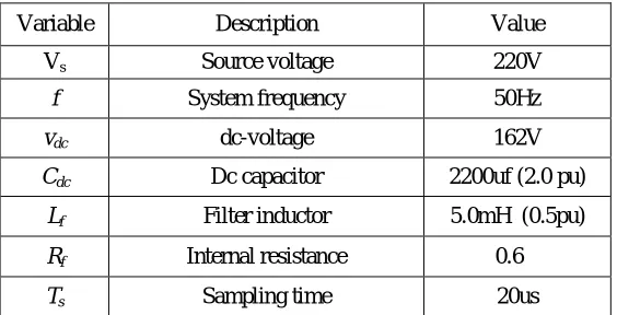
A simulation model is developed in a MATLAB/ Simulink with parameters shown in Table-1. The main objective of proposed system is to verify the harmonic current in the system and as per required reference value the current compensation will provide. This system is developed in discrete time domain and simulation is performed on time 20us. Non-linear load use on this system is six-pulse rectifier.
TABLE I : SYSTEM PARAMETERS
Variable Description Value
Vs Source voltage 220V
f System frequency 50Hz
vdc dc-voltage 162V
Cdc Dc capacitor 2200uf (2.0 pu)
Lf Filter inductor 5.0mH (0.5pu)
Rf Internal resistance 0.6Ω
ISSN(Online): 2319-8753 ISSN (Print): 2347-6710
I
nternational
J
ournal of
I
nnovative
R
esearch in
S
cience,
E
ngineering and
T
echnology
(An ISO 3297: 2007 Certified Organization)
Website: www.ijirset.com
Vol. 6, Issue 7, July 2017
(a) Phase to neutral source voltage
(b) System currents before compensation
(c) System currents after compensation
(d) Single phase active filter output current
(e) Three phase active filter output current
(f) Load to neutral current
(g)
source to neutral current(h)
DC voltage converterISSN(Online): 2319-8753 ISSN (Print): 2347-6710
I
nternational
J
ournal of
I
nnovative
R
esearch in
S
cience,
E
ngineering and
T
echnology
(An ISO 3297: 2007 Certified Organization)
Website: www.ijirset.com
Vol. 6, Issue 7, July 2017
The simulation results are shown in fig.7. Phase to neutral source voltage shown in fig.7(a). It is purely sinusoidal. The active power filter start compensates current on time 0.04sec which is set in MATLAB. In this time it compensates the current harmonics, current unbalance. In fig.7(b). shows a effect of current harmonics to the system currents. After compensation the current harmonics get reduced as shown in the fig.7(c). Single- Phase active power filter compensation current shown in fig.7(d). Three-Phase active power filter output current shown in fig.7(e). Neutral currents are also important part of this control algorithm fig.7(f) shows the load to neutral current and fig.7(g) illustrated the source to neutral current. To verify the effectiveness of this control method various load added in load side. The current waveform remains sinusoidal on various load changes also. Simulation results shows how this system is effectively work to eliminate the current unbalance and harmonics. After all this processes fig.7(h). shows that DC- voltage is constant in total active power filter operation.
(a)
THD before Compensation(b)
THD after CompensationFig.8. THD Comparison of proposed system
Fig.8(a). shows that THD without active power filter compensation is 29.79% which is dangerous for the system components. By using active power filter compensation with predictive current control method THD is reduced to 3.91% as shown in fig.8(b).
VII. CONCLUSION
This control scheme is improved and developed dynamic current harmonic elimination and compensation for the renewable power generation as well as distribution systems. It improves the current quality with distortion-less current. This improved control scheme associated with the simplicity, modelling and for the implementation and utilization in any power system. Main function of this prediction control algorithm is to give effective, simple and robust solution for the active power filter performance. Simulation results show the proposed predictive algorithm is suitable and effective for the active power filter operation as compared to the traditional controllers. Stable and robust solution is obtained with compensation effectiveness of proposed shunt active power filter.
REFERENCES
[1] M. Aredes, J. Hafner, and K. Heumann, “Three-phase four-wire shunt active filter control strategies,” IEEE Trans. Power Electron., vol. 12, no. 2, pp. 311–318, Mar. 1997.
[2] S. Naidu and D. Fernandes, “Dynamic voltage restorer based on a four-leg voltage source converter,” Gener. Transm. Distrib., IET, vol. 3, no. 5, pp. 437–447, May 2009.
ISSN(Online): 2319-8753 ISSN (Print): 2347-6710
I
nternational
J
ournal of
I
nnovative
R
esearch in
S
cience,
E
ngineering and
T
echnology
(An ISO 3297: 2007 Certified Organization)
Website: www.ijirset.com
Vol. 6, Issue 7, July 2017
[4] R. de Araujo Ribeiro, C. de Azevedo, and R. de Sousa, “A robust adap-tive control strategy of active power filters for power-factor correction, harmonic compensation, and balancing of nonlinear loads,” IEEE Trans.Power Electron., vol. 27, no. 2, pp. 718–730, Feb. 2012.
[5] D. Quevedo, R. Aguilera, M. Perez, P. Cortes, and R. Lizana, “Model predictive control of an AFE rectifier with dynamic references,” IEEE Trans. Power Electron., vol. 27, no. 7, pp. 3128–3136, Jul. 2012.
[6] V. Khadkikar and A. Chandra, “A novel structure for three-phase four-wire distribution system utilizing unified power quality conditioner (UPQC),” IEEE Trans. Ind. Appl., vol. 45, no. 5, pp. 1897–1902, Sep./Oct. 2009.
[7] A. Pigazo, V. M. Moreno, and E. J. Estebanez, “A recursive park trans-formation to improve the performance of synchronous reference frame controllers in shunt active power filters,” IEEE Trans. Power Electron., vol. 24, no. 9, pp. 2065–2075, Sep. 2009.
[8] M. Aredes, H. Akagi, E. H. Watanabe, E. V. Salgado, and L. F. Encarnacao, “Comparisons between the p–q and p–q–r theories in three-phase four-wire systems,” IEEE Trans. Power Electron., vol. 24, no. 4, pp. 924–933, Sep. 2009.
[9] A. Luo, Z. Shuai, W. Zhu, and Z. J. Shen, “Combined system for har-monic suppression and reactive power compensation,” IEEE Trans. Ind. Electron., vol. 56, no. 2, pp. 418–428, Feb. 2009.
[10] T. Geyer, “Computationally efficient model predictive direct torque con-trol,” IEEE Trans. Power Electron., vol. 26, no. 10, pp. 2804–2816, Oct. 2011.
[11] M. I. M. Montero, E. R. Cadaval, and F. B. Gonzalez, “Comparison of control strategies for shunt active power filters in three-phase four-wire systems,” IEEE Trans. Power Electron., vol. 22, no. 1, pp. 229–236, Jan. 2007.
[12] L. Czarnecki, “On some misinterpretations of the instantaneous reactive power p-q theory,” IEEE Trans. Power Electron., vol. 19, no. 3, pp. 828– 836, May 2004.