Power Quality Improvement in Distribution System by
Using DSTATCOM with Predictive ANN
K. SeetharamanjaneyuluP
1
P
, G.NagarajuP
2 P , P 1 P
Pursuing M.Tech in PEED, Dept. of EEE, Narasaraopet Engineering College, Andhra Pradesh, India
P
2
P
Asst. Professor, Department of EEE, Narasaraopet Engineering College , Andhra Pradesh, India,
Abstract: Any electrical power system consists of wide range of electrical, electronic and power electronic equipment in commercial and industrial applications. The quality of the power is effected by many factors like harmonic contamination, arc in arc furnace, sag and swell due to the increment of non-linear loads such as large thyristor power converters, rectifiers, voltage and current flickering, arc in arc furnaces and switching of loads respectively which also affects the sensitive loads to be fed from the system. In This paper presents a new synchronous-reference frame (SRF)-based control method to compensate power-quality (PQ) problems(reactive power, to provide load balancing, to eliminate harmonics, to correct power factor) through a three-phase four-wire unified PQ conditioner (DSTATCOM) under unbalanced and distorted load conditions. The efficiency of the DSTATCOM depends on the performance of the efficiency control technique involved in switching the inverters. Unlike previous approaches, this paper presents a hysteresis voltage control technique of DSTATCOM based on bipolar and unipolar Pulse Width Modulation (PWM). The hysteresis voltage control has a very fast response, simple operation and variable switching frequency. To evaluate the quality of the load voltage during the operation of DSTATCOM, Total Harmonic Distortion (THD) is calculated with various controllers (PI, ANN). The proposed DSTATCOM system can improve the power quality at the point of common coupling on power distribution systems under unbalanced and distorted load conditions with SRF-EPLL control Technique. The validity of proposed method and achievement of desired compensation are confirmed by the results of the simulation in MATLAB/ Simulink.
Keywords: Distribution static compensator (DSTATCOM), enhanced phase-locked loop (EPLL), load balancing, reactive power compensation, zero voltage regulation (ZVR), artificial neural network (ANN), proportional integral (PI).
I. INTRODUCTION
Modern power systems are complex networks, where hundreds of generating stations and thousands of load centers are interconnected through long power transmission and distribution networks. Even though the power generation in most countries is fairly reliable, the quality of power is not so reliable. Power distribution system should provide their customers with an uninterrupted flow of energy at smooth sinusoidal voltage at the contracted magnitude level and frequency. Power system especially distribution systems have numerous non linear loads, which significantly affect the quality of power supplies. This ends up producing many power quality problems. Apart from non linear loads events like capacitor switching, motor starting and unusual faults could also inflict power quality problems.
There are mitigation techniques for power quality problems in the distribution system and the group of devices is known by the generic name of custom power devices (CPDs). The distribution static compensator (DSTATCOM) is a shunt-connected CPD capable of compensating power quality problems in the load current. Some of the topologies of DSTATCOM for three-phase four-wire system for the mitigation of neutral current along with power quality compensation in the source current are four-leg voltage source converter (VSC), three single-phase VSCs, three-leg VSC with split capacitors, three-three-leg VSC with zigzag transformer and three-leg VSC with neutral terminal at the positive or negative of dc bus. The voltage regulation in the distribution feeder is improved by installing a shunt compensator. There are many control schemes reported in the literature for control of shunt active compensators such as instantaneous reactive power theory, power balance theory, synchronous reference frame theory, symmetrical components based, etc. The synchronous reference frame theory is used for the control of the proposed DSTATCOM.
harmonics elimination, load balancing in power factor correction (PFC) and zero voltage regulation (ZVR) modes of operation of DSTATCOM in three phase distorted voltage supply system under unbalanced nonlinear loads. The EPLL is used as the basic structure for harmonic and inter harmonic estimation, and several of such sections are arranged together. Each one is adjusted to estimate a single sinusoid waveform. This control algorithm has the following features:
a. It is adaptive in nature and adopts the variations in amplitude, phase angle and frequency of the input signals.
b. Speed and accuracy of its response are under control, and performance is not affected due to noise and distortion.
c. The structure of EPLL is simple due to this reason; its implementation in real time using DSP or any other embedded controllers is easy.
d. It is a continuous time non window-based approach and offers regular adjustment to the frequency variation; also, performance does not depend upon internal parameter settings.
e. It is also able to extract accurate
fundamental components from polluted utility or supply systems.
f. It is not affected from the existence of double frequency ripples in the loop.
II. DSTATCOM AND SYSTEM CONFIGURATION
Before going to discuss about DSTATCOM, we need to know about STATCOM.A STATCOM system is nothing but a three phase inverter connected to the grid through a reactor and a connecting transformer. In the three phase inverter instead of a DC battery, a capacitor is used to provide the DC link voltage. A controller is used to control the voltages, phase and the frequency of the STATCOM to maintain synchronism with the grid. The active and reactive power transfer between the power system and the STATCOM is caused by the voltage difference across this reactance. The STATCOM is connected in shunt with the power networks at customer side, where the load compensation. All required voltages and currents are measured and are fed into the controller to be compared with the commands. The controller then performs closed loop feedback control and outputs a set of switching signals to drive the main semiconductor switches (IGBT’s, which are used at the distribution level) of the power converter accordingly. By varying the amplitude of the output voltages produced, the reactive power exchange between the converter and the ac system can be controlled.
In this way the inverter absorbs a small amount of real power from the ac system to replenish its internal losses and keep the capacitor voltage at the desired level. The mechanism of phase angle adjustment can also be used to control the var generation or absorption by increasing or decreasing the capacitor voltage, and thereby the amplitude of the output voltage produced by the inverter. A STATCOM used in the distribution system is generally called as a DSTATCOM. The DSTATCOM consists of a voltage source converter (VSC) based on self commutating semiconductor valves and a capacitor on the dc bus. This compensating device is connected at point of common coupling (PCC) through interfacing inductances. In general, the functions of DSTATCOM are reactive power compensation, harmonics elimination, along with load balancing in the distribution system in PFC and ZVR modes of operation.
Fig. 1 shows a schematic diagram of a DSTATCOM connected to a three phase ac mains having a source impedance (Rs, Ls) feeding variety of three phase loads. Interfacing inductors (Lf) are used at ac side of the VSC for reducing ripple in compensating currents. A series connected capacitor (Cf) and a resistor (Rf) represent the ripple filter installed at PCC in parallel with the loads and the DSTATCOM to filter the high frequency switching noise of the voltages at PCC. The compensating currents ( 𝑖𝐶𝑎,𝑖𝐶𝑏,𝑖𝐶𝑐) are injected by DSTATCOM to cancel harmonics/reactive power components of load currents.
III. CONTROL ALGORITHM OF DSTATCOM
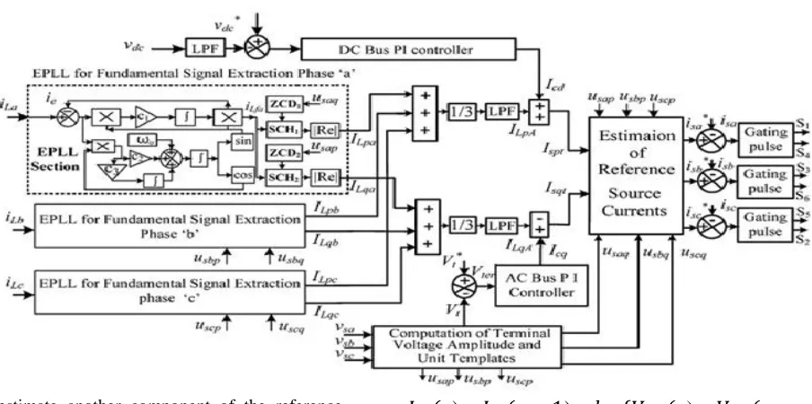
Fig. 2 shows a block diagram of proposed control algorithm based on EPLL scheme for extraction of reference source currents Basic equations for estimation of different control signals of control algorithm are given as.
A. Estimation of In- Phase and Quadrature Unit Voltage Templates
Three phase sensed PCC voltages (Vsa, Vsb, Vsc) may consist of harmonics and negative sequence components. These PCC voltages are processed through band pass filters (BPFs) to filter noise and harmonics. These filtered PCC voltages may also be unbalanced. The individual amplitude of each of these three phase voltages are estimated through squaring them and then processed through low passed filters (LPFs) as follows:
𝑣
𝑡𝑎′=
�
[2
�
𝑣𝑠𝑎2
2
�
]
,
𝑣
𝑡𝑏′=
��
2
�
𝑣𝑠𝑏2
2
��
𝑎𝑛𝑑
𝑣
𝑡𝑐′=
�
[2
�
𝑣𝑠𝑐22
�
]
After processing, these voltages (𝑣𝑡𝑎′ ,𝑣𝑡𝑏′ , 𝑣𝑡𝑐′ ) through LPFs, these are constant valued amplitudes represented as Vta, Vtb, and Vtc for phases a, b, and c.
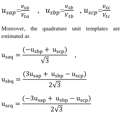
Inphase unit templates of PCC voltages are estimated as
𝑢
𝑠𝑎𝑝=
𝑣𝑉𝑠𝑎𝑡𝑎,
𝑢
𝑠𝑏𝑝=
𝑉𝑣𝑠𝑏𝑡𝑏,
𝑢
𝑠𝑐𝑝=
𝑣𝑉𝑠𝑐𝑡𝑐Moreover, the quadrature unit templates are estimated as
u
saq=
(
−
u
sbp+ u
scp)
√
3
,
u
sbq=
(3u
sap+ u
sbp−
u
scp)
2
√
3
u
scq=
(
−
3u
sap+ u
sbp−
u
scp)
2
√
3
The amplitude of PCC voltages is estimated as
𝑣
𝑡′=
�
2(
𝑣
𝑠𝑎 2+
𝑣
𝑠𝑏2
+
𝑣
𝑠𝑐2)
3
This amplitude
𝑣
𝑡′ may have ripples because of fundamental negative sequence voltage present inPCC voltages. This
𝑣
𝑡′ is processed through LPF to achieve amplitude of fundamental positive-sequence PCC voltages and it is represented as for the control of PCC voltagesB. Estimation of Fundamental Active and Reactive Power
Components of Load Currents The fundamental active and reactive power components of load currents are estimated by using proposed control algorithm based on EPLL scheme in each phase. EPLL used in phase ‘a’ receives the input signal as the load current𝑖𝐿𝑎. Difference between 𝑖𝐿𝑎and
𝑖𝐿𝑓𝑎is the total distortion in the applied signal. It is denoted as
C. Estimation of Average Amplitude of Active and Reactive Power Components of Load Currents
The average amplitude of fundamental active and reactive powers components of the three phase load currents are estimated using the amplitude of active and reactive power components of load currents. An average value of amplitudes is estimated for load balancing and to be used in the extraction of three phase reference source current as
I
LpA=
I
Lpa+ I
Lpb3
+ I
LpcI
LqA=
I
Lqa+ I
Lqb3
+ I
LqcTo estimate another component of the reference active power component of source currents, the reference dc bus voltage is compared with sensed dc bus voltage of DSTATCOM. The dc bus voltage is regulated through PI (proportional-integral) controller which is required to maintain dc bus voltage. It is represented as Icd . The amplitude of active power component of the reference source current Ispt is estimated as the addition of required active power component of current for the self supporting dc bus of the DSTATCOM and average magnitude of active power components of load currents as
𝐼
𝑠𝑝𝑡=
𝐼
𝑐𝑑+
𝐼
𝐿𝑞𝐴E. Estimation of Amplitude of Reactive Power Component of Reference Source Currents
The amplitude of another component of reactive power component of the reference source current is calculated using a voltage PI controller over the
amplitude of the PCC voltage
𝑉
𝑡 and its reference value𝑉
𝑡∗. The voltage error𝑉
𝑡𝑒𝑟 of ac voltage at the sampling instant is given as𝑉
𝑡𝑒𝑟(
𝑟
) =
𝑉
𝑡∗(
𝑟
)
−
𝑉
𝑡(
𝑟
)
The output of the PCC voltage PI controller
𝐼
𝑐𝑞 for regulating PCC voltage to the reference or rated value at the sampling instant is given as𝐼
𝑐𝑞(
𝑟
) =
𝐼
𝑐𝑞(
𝑟 −
1
) +
𝑘
𝑝𝑡{
𝑉
𝑡𝑒𝑟(
𝑟
) -
𝑉
𝑡𝑒𝑟(
𝑟
-1)} +
𝑘
𝑖𝑡𝑉
𝑡𝑒𝑟(
𝑟
)
Fig. 2.Generation of reference source currents using the SRF-EPLL based control algorithm
where
𝐼
𝑐𝑞(
𝑟
) is a part of the reactive power
component of source current and it is named𝐼
𝑐𝑞,
𝑘
𝑝𝑡 and𝑘
𝑖𝑡 are the proportional and integral gain constants of the PCC voltage PI controller.The amplitude of reactive power component of the
reference source current
𝐼
𝑠𝑝𝑡 is estimated as the difference of output of the voltage PI controller𝐼
𝑐𝑑and the average of reactive power component of load currents𝐼
𝐿𝑞𝐴asI
spt= I
cd−
I
LqAF. Estimation of Reference Source Currents and Generation of Gating Pulses
Three phase reference source currents are estimated using amplitude of active power components of currents, reactive power components of currents, in phase unit voltage templates, and quadrature unit voltage templates. Three phase reference source active and reactive power components of currents are estimated as
𝑖𝑠𝑎𝑞 = 𝐼𝑠𝑞𝑡𝑢𝑠𝑎𝑞, 𝑖𝑠𝑏𝑞 = 𝐼𝑠𝑞𝑡𝑢𝑠𝑏𝑞, 𝑖𝑠𝑐𝑞 = 𝐼𝑠𝑞𝑡𝑢𝑠𝑐𝑞
Total reference source currents are estimated after the addition of reference active and reactive power components of source currents as
𝑖
𝑠𝑎∗=
𝑖
𝑠𝑎𝑝+
𝑖
𝑠𝑎𝑞,
𝑖
𝑠𝑏∗=
𝑖
𝑠𝑏𝑝+
𝑖
𝑠𝑏𝑞,
𝑖
𝑠𝑐∗=
𝑖
𝑠𝑐𝑝+
𝑖
𝑠𝑐𝑞These estimated three phase reference source
currents (
𝑖
𝑠𝑎∗,
𝑖
𝑠𝑏∗ ,𝑖
𝑠𝑐∗)
are compared with sensed source currents (𝑖
𝑠𝑎,
𝑖
𝑠𝑏,𝑖
𝑠𝑐)
to estimate the current errors. Using PI controllers, these current errors are amplified and outputs of PI current controllers are compared with carrier signals to generate PWM pulses for switching devices insulated-gate bipolar transistors (IGBTs) (S1 to S6) of VSC.IV. RESULTS AND DISCUSSION
The Fig.1 shows the basic test system used to carry out the various D-STATCOM simulations presented in this section. It mainly consists of basic distribution system of three phase 4 wire with supply of 110 Volt line to line voltage, and a load with linear, nonlinear loads. Across this a ripple
filter and DSTATCOM with interfacing
inductances are connected. And the DSTATCOM is controlled by a control algorithm which is used generate the gating signals to the DSTATCOM. This is shown in Fig.2.
The total system is connected by using MATLAB\Simulink. Then the results or observed through scopes. Here we are going to discuss the performance of the proposed algorithm and performance of the linear and non-linear algorithms using DSTATCOM technique.
Performance of the Proposed Control Algorithm
Fig.3 shows simulation diagram of the proposed control algorithm of DSTATCOM with ANN
controller. The main input s to the controller is load
Fig.3. Simulation diagram of controlling circuit to the DSTATCOM with ANN controller
Currents (𝑖𝐿𝑎,𝑖𝐿𝑏,𝑖𝐿𝑐 ), DC bus voltage (vRdcR), and source voltages (𝑣𝑠𝑎,𝑣𝑠𝑏,𝑣𝑠𝑐) and load voltages. By using these inputs the controller circuit gives the reference source currents which are used to produce controlled gating pulses to the DSTATCOM. The results of the test system are analyzed as follows:
Performance of the test system without DSTATCOM:
Fig.4 (a) Source current of the test system without DSTATCOM
Fig.4 (b) FFT analysis of source current of test system without DSTATCOM
From the Fig.4 (b) it observes that the %THD of the source current is 28.04% which is very high. So that this requires the compensating devises, to eliminate harmonics and increase the terminal voltage.
Performance of the test system with
controlling circuit with PI controller and DSTATCOM:
This can eliminate the harmonics in the test system, reduces the %THD to 5.63%, and also reduces load current and increases terminal voltage. Which is shown in below Fig.5 (a)-(d)
Fig.5 (a) Load voltage and load current of test system with PI controller and DSTATCOM
Fig.5 (b) Load voltage and source current of test system with PI controller and DSTATCOM
Fig.5 (c) FFT analysis of source current of test system with PI controller and DSTATCOM
Fig.5 (d) Terminal voltage of test system with PI controller and DSTATCOM
Performance of the test system with
controlling circuit with ANN controller and DSTATCOM:
The performance of the test system with control circuit is so much better than before cases (A&B), the draw backs in the above cases are rectified with this control arrangement the Fig.6 (a)-(d), shows the results of test system with ANN & DSTACOM.
Fig.6 (a) Load voltage and load current of test system with ANN controller and DSTATCOM
Fig.6 (b) Load voltage and source current of test system with ANN controller and DSTATCOM
Fig.6 (c) FFT analysis of source current of test system with ANN controller and DSTATCOM
Fig.6 (d) Terminal voltage of test system with ANN controller and DSTATCOM
The total performance of the test is explained by following Table.1.
Table.1 Comparison results of test system
From the above Table.1 this observe that the variation of results for three different cases. And also improvement in the results as compared with previous cases.
V. CONCLUSION
A new control algorithm of DSTATCOM has been implemented for compensation of three phase linear and nonlinear loads. The performance of DSTATCOM and its control algorithm has been
demonstrated for reactive power compensation, harmonics elimination, and increase in voltage regulation at PCC, under nonlinear and mixed loads. Test results have shown that the proposed control algorithm has a fast response for the extraction of fundamental components of load currents under noisy and distorted supply voltages. In all operating conditions, the THD of source current has been observed within an IEEE 519– 1992 standard limit of 6%. The performance of DSTATCOM and its control has been found satisfactory under varying load conditions. The dc bus voltage of the DSTATCOM has also been regulated without any overshoot to the desired value under varying load conditions.
In this project “Power quality improvement in distribution system by using DSTATCOM with predictive ANN” an advanced ANN controller is used instead of PI controller. Because of this advanced control we got best results compared to other controllers.
REFERENCES
(1) Bhim Singh, Fellow, IEEE, and Sabha Raj Arya, Member, IEEE Implementation of Single-Phase “Enhanced Single-Phase-Locked Loop-Based Control Algorithm for Three-Phase DSTATCOM” IEEE transactions on power delivery, VOL. 28, NO. 3, JULY 2013.
(2) F. Barrero, S. Martínez, F. Yeves, and P. M. Martinez, “Active power filters for line conditioning: A critical evaluation,”IEEE Trans. Power Del., vol. 15, no. 1, pp. 319–325, Jan. 2000.
(3) Terciyanli, T. Avci, I. Yilmaz,C. Ermis, K. Kose, A. Acik, A. Kalaycioglu, Y. Akkaya, I. Cadirci, and M. Ermis, “A current source converter based active powerfilter for mitigation of harmonics at the interface of distribution and transmission systems,”IEEE Trans. Ind. Appl., vol. 48, no. 4, pp. 1374–1386, Jul./Aug. 2012.
(4) L. Sainz and J. Balcells, “Harmonic interaction influence due to current source shuntfilters in networks supplying nonlinear loads,”IEEE Trans. Power Del., vol. 27, no. 3, pp. 1385–1393, Jul. 2012.
(6) B. Singh and J. Solanki, “A comparison of control algorithms for DSTATCOM,” IEEE Trans. Ind. Electron., vol. 56, no. 7, pp. 2738–2745, Jul. 2009.
(7)G. Chyun, G. C. Hsieh, and J. C. Hung, “Phase-locked loop techniques-A survey,”IEEE Trans. Ind. Electron., vol. 43, no. 6, pp.609–615, Dec. 1996.
(8)F. Barrero, S. Martínez, F. Yeves, and P. M. Martinez, “Active power filters for line conditioning: A critical evaluation,”IEEE Trans. PowerDel., vol. 15, no. 1, pp. 319–325, Jan. 2000.
(9) A. M. Massoud, S. J. Finney, and B. W. Williams, “Review of harmonic current extraction techniques for an active powerfilter,” inProc. 11P
th
P
Int. Conf. Harmonies Quality Power, 2004, pp. 154–159.
(10) A. Terciyanli, T. Avci, I. Yilmaz,C. Ermis, K. Kose, A. Acik, A. Kalaycioglu, Y. Akkaya, I. Cadirci, and M. Ermis, “A current source converter based active powerfilter for mitigation of harmonics at the interface of distribution and transmission systems, ”IEEE Trans. Ind. Appl., vol. 48, no. 4, pp. 1374–1386, Jul./Aug. 2012.
(11) L. Sainz and J. Balcells, “Harmonic interaction influence due to current source shuntfilters in networks supplying nonlinear loads, ”IEEE Trans. Power Del., vol. 27, no. 3, pp. 1385–1393, Jul. 2012.
(12) J. W. Dixon, J. J. Garcia, and L. Moran, “Control system for threephase active powerfilter which simultaneously compensates power factor and unbalanced loads, ”IEEE Trans. Ind. Electron., vol. 42, no.6, pp. 636–641, Dec. 1995.
(13) B. Singh and J. Solanki, “A comparison of control algorithms for DSTATCOM,” IEEE Trans. Ind. Electron., vol. 56, no. 7, pp. 2738–2745, Jul. 2009.
(14) G. Chyun, G. C. Hsieh, and J. C. Hung, “Phase-locked loop techniques-A survey,”IEEE Trans. Ind. Electron., vol. 43, no. 6, pp. 609–615, Dec. 1996.
(15) F. Gonzalez-Espín, E. Figueres, and G. Garcera, “Garcera, An adaptive synchronous reference frame phase-locked loop for power quality improvement in a polluted utility grid,”IEEETrans.Ind.Electron., vol. 59, no. 6, pp. 2718–2731, Jun. 2012.
(16) B. Singh and S. Sharma, “Design and implementation of four-leg voltage source converter based vfc for autonomous wind energy conversion system,”IEEE Trans. Ind. Electron., vol. 59, no. 12, pp. 4694–4703, Dec. 2012.
(17) F. Liccardo, P. Marino, and G. Raimondo, “Robust and fast three-phase PLL tracking system,”IEEE Trans. Ind. Electron., vol. 58, no. 1, pp. 221–231, Jan. 2011.
(18) H.Awad, J.Svensson, andM. J.Bollen, “Tuningsoftware phase-locked loop for series-connected converters,” IEEE Trans. Power Del., vol. 20, no. 1, pp. 300–308, Jan. 2005.
(19) C. H. da Silva, R. R. Pereira, L. E. B. da Silva, G. Lambert-Torres, B. K. Bose, and S. U. Ahn, “A digital PLL scheme for three-phase system using modified synchronous reference frame,”IEEE Trans. Ind. Electron., vol. 57, no. 11, pp. 3814– 3821, Nov. 2010.
(20) Q. Zhang, X.-D. Sun, Y. R. Zhong, M. Matsui, and B.-Y. Ren, “Analysis and design of a digital phase-locked loop for single-phase grid connected power conversion systems, ”IEEE Trans. Ind. Electron., vol. 58, no. 8, pp. 3581–3592, Aug. 2011.
(21) X. Guo, W. Wu, and Z. Chen, “Multiple-complex coefficient-filterbased phase-locked loop and synchronization technique for three-phase grid-interfaced converters in distributed utility networks,”IEEE Trans. Ind. Electron., vol. 58, no. 4, pp. 1194–1204, Apr. 2011.
(22) P. Karuppanan and K. K. Mahapatra, “PLL with fuzzy logic controller based shunt active powerfilter for harmonic and reactive power compensation,” inProc. India Int. Conf. Power Electron., 2011, pp. 1–6.
(23) V. Kaura and V. Blasko, “Operation of a phase-locked loop system under distorted utility conditions,”IEEE Trans. Ind. Appl., vol. 33, no. 1, pp. 58–63, Jan./Feb. 1997.
(24) M. K. Ghartemani, B. T. Ooi, and A. Bakhshai, “Application of enhanced phase-locked loop system to the computation of synchrophasors,”IEEE Trans. Power Del., vol. 26, no. 1, pp. 22–32, Jan. 2011.
(26) M. Karimi-Ghartemani and M. R. Iravani, “A method for synchronization of power electronic converters in polluted and variable-frequency environments,” IEEE Trans. Power Syst.,vol.19,no.3,pp. 1263–1270, Aug. 2004.