Division VIII
Development of a Waveguide Sensor Module for Under-Sodium Inspection of
In-Vessel Structures in a Sodium-cooled Fast Reactor
Sang-Jin Park1, Hoe-Woong Kim2, Young-Sang Joo3,†, Sung-Kyun Kim3, Jong-Bum Kim3
1 Research Assistant, SFR NSSS System Design Division, KAERI, Korea &
Ph.D. Student, Advanced Nuclear System Engineering, UST, Korea
2 Senior Researcher, SFR NSSS System Design Division, KAERI, Korea 3 Principal Researcher, SFR NSSS System Design Division, KAERI, Korea
† Professor & Corresponding Author, Advanced Nuclear System Engineering, UST, Korea
ABSTRACT
This paper deals with the development of a waveguide sensor module for under-sodium inspection of in-vessel structures in a sodium-cooled fast reactor. The developed waveguide sensor module consists of double rotation driving devices and three different types of ultrasonic waveguide sensors for versatile under-sodium inspections. To verify the feasibility of the developed waveguide sensor module and its practical applicability to the inspection of the in-vessel structures, the full-scale waveguide sensor module was manufactured. The waveguide sensor module system was organized with the ultrasonic pulser/receiver and the under-sodium inspection program developed for the remote control of the waveguide sensor movement and signal processing of the measured signal. The ranging performance test of the developed waveguide sensor module was carried out using mock-up test specimens in water and its feasibility and applicability were successfully demonstrated.
INTRODUCTION
A Sodium-cooled Fast Reactor (SFR), which uses liquid sodium (Na) as its core coolant, produces electricity using a nuclear fission reaction by fast neutrons and can highly reduce radioactivity of high-level radioactive waste because an SFR transmutes long-lived radioactive materials into short-lived or non-radioactive materials during the nuclear fission process. Therefore, an SFR has been considered a promising solution to managing the spent nuclear fuel generated from many nuclear power plants and evaluated to have the highest feasibility among Generation IV reactor models. In Korea, SFR development has been initiated since the 1990s. The design of a Prototype Generation IV SFR (PGSFR) has been undergoing and its construction is planned to start in 2022 (see. e.g., Kim (2013)). As a 150MWe reactor,
24th Conference on Structural Mechanics in Reactor Technology
BEXCO, Busan, Korea - August 20-25, 2017 Division VIII
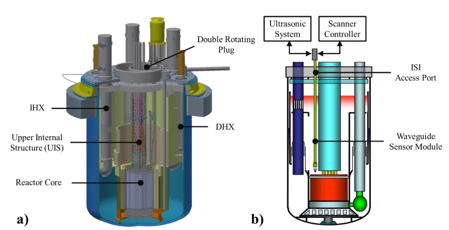
Figure 1.a) PGSFR and in-vessel structures and b) concept of under-sodium inspection in the PGSFR
Wang (2012), can be operated for a long time with a constant sensor performance because the sensor assembly is positioned in a relatively cold and low radioactive region. In Korea, Joo (2011) has continuously studied and developed a plate-type ultrasonic waveguide sensor as shown in figure 1-b) since the early 2000s.
This paper deals with the development of a waveguide sensor module employing four 10 m long plate-type ultrasonic waveguide sensors and the ranging performance test carried out to demonstrate the feasibility of the developed waveguide sensor module and its practical applicability to the inspection of the PGSFR in-vessel structures.
PLATE-TYPE ULTRASONIC WAVEGUIDE SENSOR
A plate-type ultrasonic waveguide (WG) sensor has been developed for in-service inspection of in-vessel structures in the PGSFR and its under-sodium feasibility was successfully demonstrated by Kim (2014).
Configuration
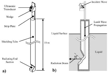
Figure 2-a) shows a 10 m long plate-type ultrasonic waveguide sensor consisting of a thin strip plate, a shielding tube, a wedge and an ultrasonic transducer. The thin strip plate is worked as a waveguide to transfer the ultrasonic energy and stainless steel is used as its material. The shielding tube isolates the plate from the surrounding liquid to avoid ultrasonic energy leakage into the liquid during wave propagation along the plate and provides a single radiation face. A commercial PZT ultrasonic transducer is fully suitable as the transmitter and receiver because the installation environment is not hazardous. The transducer is installed at the top of the plate with a solid wedge as shown in figure 2-a).
Working Principle
Figure 2.a)Plate-type ultrasonic waveguide sensor and b) working principle of the sensor
can provide the high ultrasonic energy radiation efficiency into the surrounding liquid. The incident angle is an important factor to only excite the A0-mode Lamb wave and can be calculated by Snell’s law as follows:
𝛼(𝑓𝑑) = 𝑠𝑖𝑛−1(𝑉𝑤𝑒𝑑𝑔𝑒
𝐶𝑝(𝑓𝑑)) (1)
where 𝑉𝑤𝑒𝑑𝑔𝑒 is the longitudinal wave velocity in the wedge, and 𝐶𝑝 is the phase velocity of the A0-mode Lamb wave in a plate with a thickness of 𝑑 at an excitation frequency of 𝑓. The excited Lamb wave propagates along the plate and is then radiated into the surrounding liquid in the radiating end section by mode conversion. According to Snell’s law, the radiation angle 𝜃 can be determined as
𝜃(𝑓𝑑) = 𝑠𝑖𝑛−1(𝑉𝑙𝑖𝑞𝑢𝑖𝑑
𝐶𝑝(𝑓𝑑)) (2)
where 𝑉𝑙𝑖𝑞𝑢𝑖𝑑 is the longitudinal wave velocity in the liquid. The radiated wave is reflected from possible
targets or reflectors during the propagation in the liquid and the reflected waves from targets or reflectors are then measured by the transducer under the same principle as that for the radiation. Using the measured reflected signals, finally, the targets or reflectors can be identified or visualized.
WAVEGUIDE SENSOR MODULE
24th Conference on Structural Mechanics in Reactor Technology
BEXCO, Busan, Korea - August 20-25, 2017 Division VIII
Configuration and Features
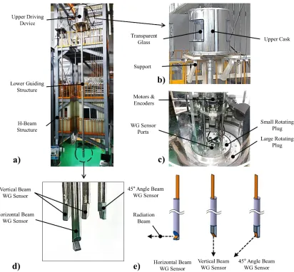
Figure 3-a) shows the waveguide sensor module installed at an H-beam structure of 13 m in height. The sensor module mainly consists of two parts, an upper driving device and a lower guiding structure. Figure 3-b) represents the upper driving device enclosed by an upper cask having a transparent glass. Inside the cask, the double rotation part consisting of small and large rotating plugs was installed and the step-motors and encoders were equipped for vertical movements, self- and double-rotations of waveguide sensors as shown in figure 3-c). In the lower guiding structure, three different types of waveguide sensors, a horizontal beam waveguide sensor for ranging inspection, two vertical beam waveguide sensors for viewing inspection and a 45° angle beam waveguide sensor for loose part identification were installed as shown in figure 3-d). Figure 3-e) illustrates radiation beams from different shapes of radiating end sections of waveguide sensors.
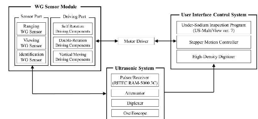
Meanwhile, the developed waveguide sensor module can be functionally divided into two parts, a sensor part and a driving part, and they are systematically connected to an ultrasonic system and a user interface control system as depicted in figure 4.
Figure 4. Connection diagram of waveguide sensor module system
Ultrasonic System
As the ultrasonic wave generated from the transducer should travel over 20 m considering its returning in the waveguide sensor, the high power ultrasonic excitation is advantageous to obtain a high Signal-to-Noise Ratio (SNR). Accordingly, a RITEC RAM-5000 3C which is widely known as a high-power ultrasonic pulser/receiver and provides total three high-power-output channels was employed as the most important instrument in the ultrasonic system. And it was linked with the sensor part in the waveguide sensor module and also a high-density digitizer in the user interface control system. For wave generation, a high cycled tone burst was used as the input signal and amplified before being sent to the ultrasonic transducer to minimize the dispersion effect of the A0-mode Lamb wave. In addition, measured signals by the ultrasonic system were delivered to the high-density digitizer before being analysed by the under-sodium inspection program. Meanwhile, an attenuator, a diplexer and an oscilloscope were accessorily and optionally used with the pulser/receiver in the ultrasonic system to improve the signal sensitivity.
Under-Sodium Inspection Program
To operate the waveguide sensor module, an under-sodium inspection program (US-MultiView ver. 7) has also been developed using the National Instruments LabVIEW software. This program is the main component and connected with other hardware components (a stepper/servo motion controller and a high-density digitizer) in the user interface control system. In addition, it is systematically connected with the driving part in the waveguide sensor module through the motor driver and acquires the ultrasonic signals from the ultrasonic system as depicted in figure 4. Using this program, therefore, it is possible to control the movements of the sensor module and to acquire the ultrasonic signals including the pre and post signal processing by digital signal processing functions (averaging, FFT, mapping, etc). The developed program consists of three sub-programs: the ranging, viewing and identifying programs as shown in figure 5-a). These sub-programs have generally identical functions and configurations but different scanning and image mapping functions based on the different inspection strategies.
Scanning Mechanism Using Double Rotation
24th Conference on Structural Mechanics in Reactor Technology
BEXCO, Busan, Korea - August 20-25, 2017 Division VIII
Figure 5. a) Under-sodium inspection program (US-MultiView ver. 7) and b) schematic of double rotation driving
compared with those in a pressurized water reactor. In the PGSFR, a double rotation mechanism by double rotating plugs has been proposed for the under-sodium inspection using the waveguide sensor module. The central axes of the small and large rotating plugs are different from each other as illustrated in figure 5-b). Using these eccentric rotations of double rotating plug, the scanning region for the viewing inspection of the nuclear fuel assembly can be entirely covered. In ranging and identification inspections, one of two rotating plugs is usually utilized for the single rotation of the waveguide sensor but the double rotation can be used for the waveguide sensor positioning to a certain coordinate. A coordinate point translated by the rotation of the small rotating plug at a given rotation of the large rotating plug is determined through the following equation.
𝐴′(𝑥′, 𝑦′) = 𝑅(𝑥
𝑓, 𝑦𝑓, 𝜙) ∙ 𝐴(𝑥, 𝑦) (3)
where 𝐴(𝑥, 𝑦) is a certain coordinate point at the double rotating plug, and 𝐴′(𝑥′, 𝑦′) is a coordinate point after the rotation by angle 𝜙 to central point (𝑥𝑓, 𝑦𝑓) of the small rotating plug. In addition, 𝑅(𝑥𝑓, 𝑦𝑓, 𝜙) is
a composite transformation matrix and is given by
𝑅(𝑥𝑓, 𝑦𝑓, 𝜙) = (
𝑐𝑜𝑠𝜙 −𝑠𝑖𝑛𝜙 𝑥𝑓(1 − 𝑐𝑜𝑠𝜙) + 𝑦𝑓𝑠𝑖𝑛𝜙
𝑠𝑖𝑛𝜙 𝑐𝑜𝑠𝜙 𝑦𝑓(1 − 𝑐𝑜𝑠𝜙) − 𝑥𝑓𝑠𝑖𝑛𝜙
0 0 1
) (4)
DEMONSTRATION TEST AND RESULTS
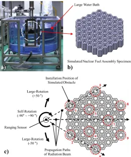
To demonstrate the feasibility and applicability of the developed waveguide sensor module for inspection of the PGSFR in-vessel structures, a ranging performance test was first carried out. The ranging is the inspection technique which monitors possible obstacles between the top of the reactor core and the bottom of the upper internal structure. Since the refueling of the PGSFR is conducted with the rotations of the double rotating plug in the reactor head, one must be ensured that there are no obstacles between the top of the reactor core and the bottom of the upper internal structure which can disturb the rotations of the double rotating plug prior to the refueling. For the test, nine obstacle specimens having the same dimensions with those of the nuclear fuel specimen were prepared and placed on the simulated nuclear fuel assembly specimen in a large water bath as represented in figure 6. The horizontal beam waveguide sensor in the
waveguide sensor module was used as the inspection sensor and self-rotated from -90° to 90° with an
movements as described in figure 6-c). The test was repeated at three different pre-determined positions to identify all obstacles including hidden obstacles behind others placed along the same propagation path of the ultrasonic wave. A nine-cycle tone burst centered at 1.0 MHz was used as the excitation input and measured signals were analyzed by the developed under-sodium inspection program. Figure 7 shows a resulting image that combines the results obtained from three different positions. From the result, one can clearly see that all obstacles are well identified by the proposed inspection technique using the developed waveguide sensor module.
Figure 6. a) Test setup, b) test specimen, and c) schematic of ranging performance test
24th Conference on Structural Mechanics in Reactor Technology
BEXCO, Busan, Korea - August 20-25, 2017 Division VIII
CONCLUSION
In this work, the 10 m long waveguide sensor module and the under-sodium inspection program have been newly developed for the inspection of in-vessel structures in the PGSFR. The developed sensor module consists of an upper driving device and a lower guiding structure employing three different types of waveguide sensors. The double rotating mechanism was also equipped for the efficient movement of the sensor. By using the developed under-sodium inspection program, all movements of the waveguide sensor were remotely controlled and the measured signals were successfully analyzed. A ranging performance test was carried out for nine obstacle specimens in water to demonstrate the feasibility and applicability of the developed sensor module and test results showed that all obstacles could be well detected by the proposed inspection technique.
ACKNOWLEDGEMENT
This study was supported by the National Research Foundation of Korea grant funded by the Korea government (Ministry of Science, ICT and Future Planning).
REFERENCES
Kim, Y. I., et al., (2013), “Status of SFR Development in Korea”, Int. conf. on Fast Reactors and Related Fuel Cycles: Safe Technologies and Sustainable Scenarios (FR 13), 4-7 May, Paris, France. Griffin, J. W., et al., (2009). “Under-Sodium Viewing: A Review of Ultrasonic Imaging Technology for
Liquid Metal Fast Reactor”, Pacific Northwest National Laboratory Report, PNNL-18292. Barrett, L. M., et al., (1984), “Ultrasonic Viewing in Fast Reactors”, Physics in Technology, Vol. 15, No. 6,
pp. 308-314.
Karasawa, H., et al., (2000), “Development of Under-sodium Three-dimensional Visual Inspection
Technique Using Matrix-arrayed Ultrasonic Transducer”, Journal of Nuclear Science and Technology, Vol. 37, No. 9, pp. 308-314.
Swaminathan, K., et al., (2012), “An Ultrasonic Scanning Technique for In-Situ ‘Bowing’ Measurement of
Prototype Fast Breeder Reactor Fuel Sub-Assembly”, IEEE Transactions on Nuclear Science, Vol. 59, No. 1, pp. 174-181.
Watkins, R. D., et al., (2000), “A Proposed Method for Generating and Receiving Narrow Beams of
Ultrasound in the Fast Reactor Liquid Sodium Environment”, Ultrasonics, Vol. 2, No. 1, pp. 7-12.
Wang, K., et al., (2012), “Ultrasonic Waveguide Transducer for Under-Sodium Viewing in SFR”, IJNESE,
Vol. 2, No. 2, pp. 39-44.
Joo, Y. S., et al, (2011). “Development of Ultrasonic Waveguide Sensor for Under-Sodium Inspection in a Sodium-Cooled Fast Reactor”, NDT&E International, Vol.44, p. 239-246.