Volume 3, No. 2, March-April 2012
International Journal of Advanced Research in Computer Science
RESEARCH PAPER
Available Online at www.ijarcs.info
ISSN No. 0976-5697
Stable And Energy Efficient Routing For Mobile Ad-Hoc Networks Using Backbone
Nodes
MahendraKumar S*
Asst. Prof., Department of ECE
Velalar College of Engineering and Technology Erode, Tamil Nadu, India.
Senthil Prakash K
Asst. Prof., Department of ECE
Velalar College of Engineering and Technology Erode, Tamil Nadu, India.
Chandrasekaran V
Asst. Prof. (Sr.Gr), Department of ECE Velalar College of Engineering and Technology
Erode, Tamil Nadu, India. [email protected]
Dr.R.Sasikala
Professor, Department of IT, K.S.Rangasamy College of Technology
Tiruchengode, Tamil Nadu, India. [email protected]
Abstract: Energy efficient routing and power control techniques in wireless ad hoc networks have drawn considerable research interests recently. Mobile Ad hoc networking is a challenging task due to the lack of network resources as well as the frequent changes in network topology. A lot of research has been done on supporting QoS in the Internet and other networks, but they are not suitable for mobile Ad hoc networks. This research uses a scheme to improve existing on-demand routing protocols by introducing the concept of stable backbone based node scheme in network topologies scenario. Our proposed scheme is done for achieving QoS in terms of packet delivery, multiple connections, better power management and stable routes. The scheme combines two basic features to achieve QoS; these are stable routing and concept of battery power. The scheme has been incorporated using AODV protocol and it is clearly shown that the protocol that is used in this research performs very well for different network scenarios, The extensive simulation has been done for the performance evaluation; it clearly shows that the scheme performs very well with increasing packet delivery for different network scenarios.
Keywords: Ad-hoc; Energy Efficient Routing; Backbone nodes; AODV; DSR and SBNRP.
I. INTRODAUCTION
Wireless Ad Hoc networks have found many applications in battlefield, disaster rescue and conventions [1], where fixed communications infrastructures are not available and quick network configurations are needed. A Mobile Ad-hoc Network is a collection of mobile devices that are equipped with interfaces and networking capability. These devices can communicate with another node within their radio range. A Mobile Ad-hoc network is also called as MANET. Each device in a MANET is free to move independently in any direction, and will therefore change its links to other devices frequently. Each must forward traffic unrelated to its own use, and therefore be a router. The primary challenge in building a MANET is equipping each device to continuously maintain the information required to properly route traffic. Such networks may operate by themselves or may be connected to the larger Internet.
This research addresses the problem of routing in mobile ad hoc network. Since mobile nodes in mobile ad hoc network can move randomly the topology may change arbitrarily and frequently at unpredictable times. Transmission and reception parameters may also impact the topology. So it is very difficult to find and maintain an optimal route. The routing algorithm must react quickly to topological changes. Due to dynamic nature of MANETs [2], the problem of broken path becomes prominent. Most of the existing protocols maintain single routing path and rediscover the new path whenever a link fails.
A scheme has been proposed here which takes the advantage of stable backbone nodes to provide the alternate path in case of a link failure. This scheme can be incorporated in any existing on demand routing protocol to improve the performance. The efforts in this paper have been made to incorporate the scheme on AODV [3] and DSR [4].
A MANET is suitable for some specific applications such as military applications, classrooms, emergency search and rescue operations, conferences and meetings etc. Routing in Ad-hoc networks experience more failures than in any other networks. Hence a routing protocol is required that considers the link failure and therefore improves the performance. Link failure occurs mainly due to the node mobility and lack of network resources. In this research Selection of Backbone Nodes Routing Protocol (SBNRP) is considered which allows mobile nodes to maintain routes to destinations with more stable route selection. Quality of service means providing a set of service requirements to the flows while routing them through the network. A new scheme has been suggested which combines two basic features to achieve QoS; these are stable routing and concept of battery power. The scheme uses backbone nodes for stable routes and uses power factor to determine active nodes to participate in routing.
II. ROUTINGPROTOCOLCLASSIFICATION
a route for packet delivery and deliver the packet to the correct destination. Routing protocol in Ad-hoc network is classified into two categories. They are:
A. Table Driven or Pro-active Protocols:
This routing protocol finds a route continuously and maintains one or more tables that contain the routing information from each node to every other node within the network. All nodes will keep on updating these tables. This protocol is not suitable for larger networks, as it needs to maintain node entries for each and every node in the routing table. This causes more overhead in the routing table leading to consumption of more bandwidth. Some of the famous pro-active protocols are: GSR [5], WRP [6], ZRP [7], STAR [8] etc. This type of protocols maintains fresh lists of destinations and their routes by periodically distributing routing tables throughout the network. The main disadvantages of such algorithms are:
a. Respective amount of data for maintenance. b. Slow reaction on restructuring and failures.
B. On Demand or Re-active Protocols:
In this routing protocol, routes are created only when required. If a node wants to send a packet to another node then this protocol searches for the route in an on-demand manner and establishes the connection in order to transmit and receive the packet. The route remains valid until the destination is achieved and the route is no longer needed. Some of the famous On Demand routing protocols are: DSR [4], RDMAR [9], AODV [3] etc. This type of protocols finds a route on demand by flooding the network with Route Request packets. The main disadvantages of such algorithms are:
a. High latency time in route finding.
b. Excessive flooding can lead to network clogging.
C. Flow-oriented Routing:
This type of protocols finds a route on demand by following present flows. One option is to unicast consecutively when forwarding data while promoting a new link. The main disadvantages of such algorithms are:
a. Takes long time when exploring new routes without a prior knowledge.
b. May refer to entitative existing traffic to compensate for missing knowledge on routes.
D. Hybrid (Both Pro-active and Reactive) Routing:
This type of protocols combines the advantages of proactive and of reactive routing. The routing is initially established with some proactively prospected routes and then serves the demand from additionally activated nodes through reactive flooding. The choice for one or the other method requires predetermination for typical cases. The main disadvantages of such algorithms are:
a. Advantage depends on number of Mathavan nodes activated.
b. Reaction to traffic demand depends on gradient of traffic volume.
E. Hierarchical Routing Protocols:
With this type of protocols the choice of proactive and of reactive routing depends on the hierarchic level where a node resides. The routing is initially established with some proactively prospected routes and then serves the demand from
additionally activated nodes through reactive flooding on the lower levels. The choice for one or the other method requires proper attributation for respective levels. The main disadvantages of such algorithms are:
a. Advantage depends on depth of nesting and addressing scheme.
b. Reaction to traffic demand depends on meshing parameters.
F. Power-aware Routing Protocols:
Energy required to transmit a signal is approximately
proportional to dα, where d is the distance and a is the
attenuation factor or path loss exponent, which depends on the
transmission medium. When α = 2 (which is the optimal case), transmitting a signal half the distance requires one fourth of the energy and if there is a node in the middle willing to spend another fourth of its energy for the second half, data would be transmitted for half of the energy than through a direct transmission – a fact that follows directly from the inverse square law of physics. The main disadvantages of such algorithms are:
a. This method induces a delay for each transmission. b. No relevance for energy network powered transmission
operated via sufficient repeater infrastructure.
III. DYNAMICSOURCEROUTINGPROTOCOL
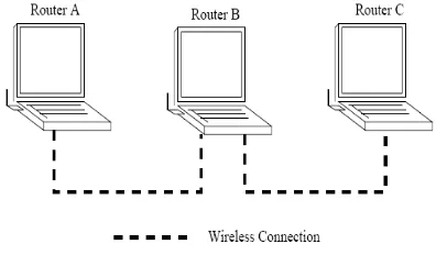
The Dynamic Source Routing (DSR) [4] protocol is a distance-vector routing protocol for MANETs. When a node generates a packet to a certain destination and it does not have a known route to that destination, this node starts a route discovery procedure. There are two main operations in DSR[4], route discovery and route maintenance. Figure 1 shows a simple example for DSR[4].
[image:2.612.360.558.499.615.2]Routers A, B, and C form a MANET. Routers A and C are disconnected, while both of them connect to router B. Assume that at the beginning, the route caches that memorize previous routes in the routers are empty. When Router A wants to send a packet to Router C, it broadcasts a route request to start the corresponding route discovery procedure.
Figure 1. Example of DSR
The route maintenance procedure is used when routes become invalid due to the unpredictable movement of routers. Each router monitors the links that it uses to forward packets. Once a link is down, a route error packet is immediately sent to the initiator of the associated route. Therefore, the invalid route is quickly discarded. Since DSR[4] discovers routes on-demand, it may have poor performance in terms of control overhead in networks with high mobility and heavy traffic loads. Scalability is said to be another disadvantage of DSR[4], because DSR[4] relies on blind broadcasts to discover routes.
IV. AD-HOCONDEMANDDISTANCEVECTOR ROUTINGPROTOCOL
AODV [3] is a very simple, efficient, and effective routing protocol for Mobile Ad-hoc Networks which do not have fixed topology. Each node in the network maintains a routing table with the routing information entries to its neighboring nodes, and two separate counters: a node sequence number and a broadcast-id. When a node has to communicate with another, it increments its broadcast-id and initiates path discovery by broadcasting a route request packet RREQ to its neighbours. The RREQ contains the following fields: addr, source-sequence#, dest-addr, dest-source-sequence#, hop-cnt.
[image:3.612.39.286.408.575.2]The figure below is an example, which shows how the route to the destination is found by AODV routing protocol. Source ’S’ has to send data to destination. It sends RREQ to its neighbours A, B, C. B finds the path in its routing table with the destination sequence number s1 and hop count c1 and then sends RREP to S. C sets up reverse path and forwards RREQ to its neighbours D and E. Similarly E sets up reverse path and forwards REQ to its neighbours F and G.
Figure 2. Example of AODV routing protocol
E deletes the reverse path after a time out period as it does not receive any RREPs from F and G. D finds the path with destination sequence number s2 which is greater than s1 and hop count c1 in its routing table and sends RREP to C. C receives RREP from D and sets up forward path and forwards RREP to S.
A sets reverse path; forwards RREQ to its neighbours; receives RREP (with path of hop count c2 which is greater than c1); sets forward path; and forwards this RREP to S. S chooses path info from C giving first priority to the path with greatest destination sequence number and then second priority to the path with smallest hop count. Though path given by A is of
smallest hop count, it is ignored because the destination sequence number is greater than the path from C.
V. SELECTIONOFBACKBONENODESROUTING PROTOCOL
In this research, we proposed routing protocol “Selection of Backbone Nodes Routing Protocol (SBNRP)” takes the concept of On Demand Routing along with a new concept of backbone nodes with power factor. The protocol is explained with an example that is given below:
The proposed scheme takes care of on demand routing along with a new concept of backbone nodes. These backbone nodes help in reconstruction phase in the fast selection of new routes. Selection of backbone nodes is made upon availability of nodes. Each route table has an entry for number of backbone nodes attached to it. Whenever need for a new route arises in case of route break, check for backbone nodes are made, and a new route is established. Same process is repeated in route repair phase. Route tables are updated at each hello interval as in AODV [3] with added entries for backbone nodes. Backbone nodes are nodes at the one hop distance from its neighbor. Backbone nodes are those nodes which are not participating in route process currently or nodes which enter the range of transmission during routing process. As nodes are in random motion for a scenario, so there is every possibility that some nodes are idle and are in the vicinity of the routing nodes.
Whenever a break in the route phase occurs due to movement of participant node, node damage or for other reasons; theses idle nodes which have been termed as backbone nodes take care of the process and start routing. The whole process becomes fast and more packet delivery is assured. The changes in the existing protocol are required at route reply and route recovery phases. In these phases the route table is updated with entries of backbone nodes. Each route table has an entry for number of backbone nodes surrounding it and their hop distance form the node. For simplicity of the protocol the distance has been assumed to be one hop.
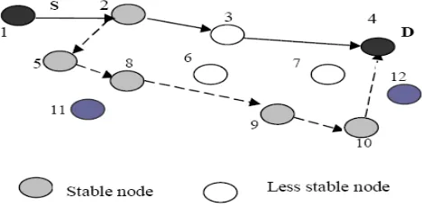
As shown in the figure Node 1 is the source and Node 4 is the destination. The route that is discovered using this protocol may not necessarily be the shortest between a source destination pair. Let us consider that Node 3 is having power status in a danger zone then though 1-2-3-4 is the shortest path but the more stable path 1-2-5-8-9-10-4 in terms of the power status is chosen. This may lead to a slight delay but it will improve the overall efficiency of the protocol by sending more packets to the destination without any link failure. When some intermediate nodes moves out of range and if link break occurs then backbone nodes take care of the process and the route is established again.
[image:3.612.330.564.605.720.2]For example in the figure 3 if Node 8 moves out of range then the newly established path will be 1-2-5-11-9-10-4. Here the Node 11 acts as a backbone node for Node 5 and Node 8. Similarly Node 12 acts as a backbone node for the nodes 4, 7 and 10. The protocol is divided into three phases. They are described below.
A. Route Request Phase (REQ):
If the source wants to send data to the destination and if it is not having any routing information then it will broadcast a Route Request packet to the neighbouring nodes. An intermediate node with an active route, upon receiving a no duplicate request records the previous node and source node information in its routing table. This is called as Backward Learning. It then broadcasts the packet or sends back a Route Reply packet to the source if it has an active route to the destination. The destination also sends a REP packet through the selected route when it receives the request. Nodes monitor the link status of the next hops in the active route. If a link break in an active route is detected, then an ERR message is sent to the source. When a node that is not a part of the route receives a REP packet that is not directed to it, it records that neighbour as its next hop to the destination in its routing table. If route break occurs it just starts the Route Construction phase from that node.
B. Route Error and Maintenance:
In this scheme, nodes those have an entry for the destination in their alternate route table transmit the packet to their next hop node. Data packets therefore can be delivered through one or more alternate routes and are not dropped when route breaks occur. When a node detects a link break, it performs a one hop data broadcast to its immediate neighbours. The node specifies that the link is disconnected and thus the packet is sent through an alternate route. Upon receiving this packet previous one hop neighbour starts route maintenance phase and constructs an alternate route through backbone nodes by checking their stability. All this route maintenance occurs under local repair scheme.
C. Local Repair:
When a link break in an active route occurs, the node upstream of that break may choose to repair the link locally. The Time to live (TTL) of the REQ should initially be set to the following value:
TTL=max (MIN_REPAIR_TTL+BN, 0.5*#HOPS) +Power status
Where the MIN_REPAIR_TTL is the last known hop count to the destination, #hops is the number of hops to the sender of the currently undeliverable packet. BN is the number of backbone nodes attached to the said node and Power status is power state of the node at that time. As 0.5* #hops is always less than MIN_REPAIR_TTL+BN. This factor is transmitted to all nodes to select best available path with maximum power.
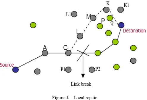
[image:4.612.325.572.57.226.2]Figure 4 gives the working of local route repair. Initial path from source node to destination node is shown via solid lines. When link breaks at node C, route repair starts, node C starts searching for new paths, buffering packets from S-A in its buffer. Node C invokes Route Request phase for ‘Destination’.
Figure 4. Local repair
Now backbone nodes are selected and proper selection of nodes is done based on power factor. The path selected becomes [C-L-M-K-Destination], instead of [C-L-P-Destination], since the node P is not in active state. Even though the route may become longer, but the selected route path is more stable and delivers more packets. Stability of route depends upon two major aspects such as: Life time and Power status.
During local repair data packets will be stored in the buffer at local originator. If, at the end of the route discovery procedure, the repairing node has not received a reply message then it transmits an ERR message to the source. On the other hand, if the node receives one or more route reply’s (REP) during the discovery period, it first compares the hop count of the new route with the value of the hop count field of the invalid route. After locally repairing the link break, if an ERR message is sent to the originating node then it will find a fresh route to the destination that is better based on the current node position.
VI. SIMULATIONANDRESULTS
Simulation study has been carried out to study the Performance study of existing different protocols. Simulation Environment used is NS2 (network simulator) version NS2.29 to carry out the process. Simulation results have been compared with AODV [3] and DSR [4]. Simulation study has been performed for packet delivery ratio, Throughput and End to End delay evaluations.
A. Packet Delivery Ratio:
Packet delivery ratio is the fraction of successfully received packets. If C is total number of flows, f is id, R is packets received from f and T is packets transmitted from f, then F can be determined by
B. End to End Delay:
average end to end delay can be calculated by using the formula.
C. Throughput:
It is defined as rate of successfully transmitted data per second in the network.
Throughput = Total number of bytes / Total end to
end delay (3)
D. Performance Comparison:
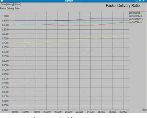
[image:5.612.329.573.52.249.2]In simulation study 15 nodes were taken in a random scenario of size 1000 × 1000. The comparison has been done at different pause times. Pause time of 10 means maximum mobility and 30 is minimum mobility. Packet delivery ratio has been explained. AODV[3] outperforms DSR[4] in congested medium. AODV[3] is delivering more packets to DSR[4] in most of the cases and has an edge over it. Selection of backbone nodes routing protocol is the overall best.
Figure 5. Packet delivery ratio comparison
[image:5.612.327.576.314.505.2]Figure shows graphical representation for end to end delay. Here it is clear that DSR[4] has more delays than AODV[3]. Selection of backbone nodes routing protocol has higher delays. This means while DSR already has a route for a certain destination SBNRP would have to send a specific request for that destination. The packets would in the meanwhile stay in the buffer until a valid route is found. This takes some time and will therefore increases the average delay. The delay for SBNRP is more and the reason is that it spends more time in calculation of stable route. SBNRP delivers even those packets, which are dropped in AODV as it has better recovery mechanism and local repair system for faster recovery. All this process increases delay but not at the cost of efficiency.
Figure 6. End to end delay comparison
Throughput in bytes per second has been calculated. DSR[4] , AODV[3] and SBNRP have an increase in throughput. The throughput increase can be further explained by TCP behaviour, such that, when ACK is not received back, TCP source retransmits data.
Figure 7. Throughput comparison
VII. CONCLUSION
[image:5.612.39.286.319.518.2]Additionally, the plan is to further evaluate the proposed scheme by using factor of power and quality of service.
VIII. REFERENCES
[1] A. Junior and R. Sofia, “Energy-efficient routing in user-centric environments,” The 2010 IEEE/ACM International Conference on Green Computing and Communications (GreenCom2010), Dez, 2010.
[2] Bulent Tavli and Wendi B. Heinzelman, “Energy-Efficient Real-Time Multicast Routing in Mobile Ad Hoc Networks”, IEEE Transactions on Computers, Vol. 60, No. 5, pp 707-722, May 2011.
[3] C.E. Perkins, E.M. Royer, “Ad-Hoc On Demand Distance Vector Routing”, Proceedings of the 2nd IEEE Workshop on Mobile Computing Systems and Applications (WMCSA), New Orleans, LA, February 1999, pp. 90-100
[4] D.B. Johnson, D.A. Maltz, "Dynamic Source Routing in Ad Hoc Networks", Mobile Computing, T. Imielinski and H. Korth, Eds., Kulwer, 1996, pp. 152-81.
[5] Tsu-Wei Chen, Mario Gerla, "Global State Routing: A New Routing Scheme for Ad-hoc Wireless Networks" Proceedings IEEE ICC 1998
[6] S. Murthy, J.J. Garcia-Luna-Aceves, "An Efficient Routing Protocol for Wireless Networks", ACM Mobile Networks and App. Journal, Special Issue on Routing in Mobile Communication Networks, Oct. 1996, pp. 183-97.
[7] Z.J. Hass, M.R. Pearlman, “Zone routing protocol (ZRP)”, Internet draft. June 1999, at www.ietf.org .
[8] J.J. Garcia, M. Spohn and D. Bayer, “Source Tree Adaptive Routing protocol”, IETF draft, October 1999.