3D SIMULATION OF STRATIFICATION IN GRAVITY DRIVEN WATER
POOL USING CATHARE
A. Srivastava, H. G. Lele, K. K. Vaze
Reactor Safety Division, Bhabha Atomic Research Centre, Mumbai, INDIA-400085 E-mail of corresponding author: [email protected]
ABSTRACT
A natural circulation vertical pressure tube type boiling light water cooled and heavy water moderated reactor design is advanced in terms of safety philosophy. One of the important passive design features of this reactor is that the decay heat removal is achieved through natural circulation of primary coolant through Isolation Condenser (ICs) submerged in Gravity Driven Water Pool (GDWP).
During transients leading to hot shutdown, the ICs are intended to remove decay heat with the help of GDWP. The ICs reject heat in this large pool of water. This sets natural circulation and further thermal stratification. The stratification may affect heat removal through ICs and further cooling of fuel. For effective heat removal through the ICs, it is very important to analyse the stratification phenomenon and its challenges to problem of heat removal in long term to maintain core coolability.
For thermal hydraulic safety analysis of reactor system, system codes like RELAP5 and CATHARE are predominately used. These system codes have detailed 6-equation two-phase 1-D models. The thermal stratification in GDWP is basically a 3D phenomenon. So far, thermal stratification problem was simulated using 1-D model and use of such model to simulate this phenomenon poses a challenge in terms of proper simulation of effective heat removal. There is a limited 3D capability in CATHARE code. It is desirable to have verification of CATHARE 3D modelling before integration of this model with complete reactor model and further integrated transient safety analysis.
The paper discusses the detailed 3D modelling of GDWP in CATHARE and simulation of stratification phenomenon during decay heat removal transient along with results.
INTRODUCTION
The advance reactor [1] is a light water cooled heavy water moderated pressure tube type boiling water reactor. During normal reactor operation, full reactor power is removed by natural circulation caused by thermo siphoning phenomenon. The main heat transport system transports heat from fuel rods to the steam drums using boiling light water in a natural circulation mode. The necessary flow rate is achieved by locating the steam drums at a suitable height above the core. By eliminating nuclear grade primary circulating pumps and their drives, and control system, all event scenarios initiating from non-availability of main pumps are therefore excluded besides providing economical advantage. The above factors result in considerable enhancement of system safety and reliability.
During normal shutdown, decay heat is removed by natural circulation in the main heat transport circuit and the heat is transferred to ultimate heat sink through main condenser. The isolation condenser system removes heat during non-availability of the main condenser. Under this scenario, core decay heat is removed by eight isolation condensers (ICs) submerged in the gravity driven water pool. The pool acts as a heat sink for passive decay heat removal system. Four isolation condensers are capable of removing 6% full power core heat (decay heat at reactor trip). Passive valves are provided on the down stream of each isolation condenser. These valves get activated at a set steam drum pressure, and establish steam flow by natural circulation between the steam drums and corresponding isolation condenser under hot shutdown. The steam condenses inside the isolation condenser pipes immersed in the GDWP and the condensate returns to the core by gravity. The IC rejects heat in large pool of water. This sets natural circulation and further thermal stratification [2]. This thermal stratification may affect the heat removal through ICs and effective cooling of fuel. For effective heat removal through the ICs, it is very important to know this stratification and its challenges to problem of heat removal in long term to maintain core cool ability.
in nature. To assess the heat removal characteristics of the pool under stratification is important to maintain the core temperature under the limit. The system code CATHARE has 3-D capability [5], which can be used along with usual 1-D reactor model to assess the heat removal through IC path under reactor shutdown with unavailability of main condenser. Such scenario can occur in reactor under Station BlackOut (SBO).
In this paper, 3-D model of the Gravity Driven Water Pool (GDWP) is developed in CATHARE. Further, a transient analysis with IC in operation for decay heat removal is analysed. The results are analysed for thermal stratification phenomenon.
GRAVITY DRIVEN WATER POOL (GDWP)
Gravity Driven Water Pool (GDWP) is located in the dome region of the reactor building and contains 8000 m3 of water inventory to cater to the various requirements as mentioned above. The GDWP consists of 8 compartments, each interconnected to each other. Each compartment of GDWP contains one Isolation Condenser (IC) for core decay heat removal during shutdown. Each compartment of GDWP is provided with outlet nozzle having perforations at various elevations for low-pressure injection into the core during LOCA. There are a number of vent pipes from tail pipe towers for vapors suppression during LOCA.
The GDWP recirculation and cooling system, consists of 4 loops, each loop consists of a pump for recirculation of GDWP inventory to prevent biological growth in GDWP, a heat exchanger to maintain the temperature of GDWP inventory below 40°C, a bypass purification line consisting of a filter & an ion exchanger to remove the suspended and ionic impurities so as to maintain the crud concentration within limits and a chemical addition tank. These loops operate in rotation with 2 loops operating at a time, which are capable of meeting 100% duty. A tank is provided outside reactor building for inventory makeup or draining of single compartment of GDWP during maintenance.
Fig.1: 3-D wire frame view of the GDWP
The GDWP has many passive roles during LOCA transient and station blackout. During LOCA, it is used for low-pressure injection in the core, act as a vapour suppression pool to suppress V1 pressure transient, further V2 heat removal through passive containment cooling feature. During station blackout, GDWP provides large water inventory as a sink to remove the decay heat of the reactor core in passive manner using ICs.
3-D MODEL DEVELOPMENT OF GDWP
arc portion of the compartment is being replaced with equivalent width. In the modified geometry, IC is placed in the center. This process is illustrated in Fig. 2.
Fig. 2: Cartesian geometry development of one GDWP compartment
The three-dimensional model of CATHARE is based on the “porous” two-fluid six equations model [5]. One set of mass, momentum and energy balance equations is written for each phase. Additional equations can be used to take into account the presence of noncondensable gases, and also to model the turbulent diffusion of one or both phase(s). The model of turbulence for each phase is a two-equation K-ε model.
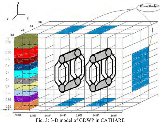
Fig. 3: 3-D model of GDWP in CATHARE
of 3.0, 2.8, 2.8 and 3.0 m length. The z-direction representing the height of GDWP compartment is divided in 10 meshes of 0.55, 0.55, 0.3, 0.4, 0.4, 0.4, 0.4, 0.3, 0.85, 0.85 m length.
The IC header and IC tubes are present in several meshes of GDWP 3-D model. An approach similar to the modelling of porous media has been used for this kind of application. Thus, one defines a scalar porosity field, which gives the relative volumes occupied by the fluid and by the structures. Regarding the Descretisation, this porosity field is defined on both the scalar nodes (i.e. volumetric porosity) and the vector nodes (i.e. surface porosity). These porosities are calculated according to the geometry and the mesh and are imposed by the user through the input deck. The volumetric momentum and energy transfers between the solid structures and the fluid are also taken into account by appropriate terms in momentum and internal energy balance equations. The 3-D model of the GDWP is shown in Fig. 3.
The space Descretisation of the equations follows the finite volume approach for all the scalar balance equations and the finite difference approach for the momentum balance equations. This difference is due to the use of the non-conservative form for the momentum balance equation. The time Descretisation of the equations is based on the semi-implicit scheme.
RESULTS AND DISCUSSION
A transient of decay heat removal from the reactor core with the help of ICs rejecting heat in GDWP is simulated using 3-D GDWP model in CATHRE. A constant 3% decay heat conditions for 7200 sec has been considered which is conservative in nature considering gradual fall of decay heat with time in reality.
The results are plotted in ZX and ZY direction. There are four planes in ZX direction in planes ZX2 And ZX3 ICs and in ZY direction in ZY3 and ZY5 planes ICs are laying. The results of the analysis are described below;
Temperature Profile
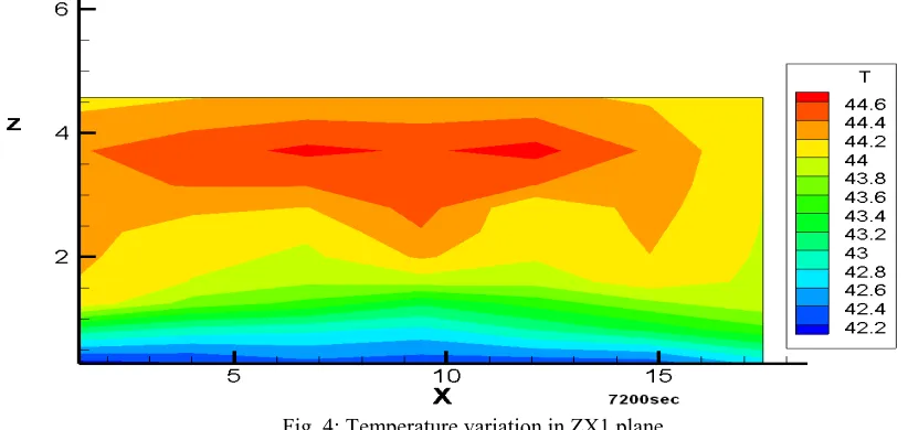
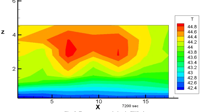
The temperature profile is shown in Fig. 4 to Fig. 7 for different ZX planes. The higher temperature in center region (ZX2 and ZX3 planes) is observed around ICs location and in the rest of the fluid region we can see the stratified layers of different temperature. The temperature range is 42.4 to 45.0 ºC (315.55-320.35 K).
Fig. 5: Temperature variation in ZX2 plane
Fig. 7: Temperature variation in ZX4 plane
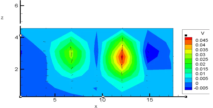
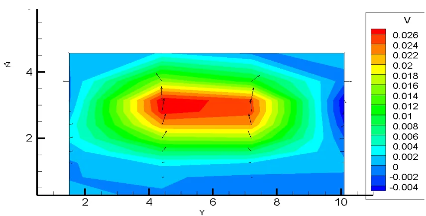
Velocity Profiles
Velocity magnitude and vectors are shown in Fig. 8 and Fig. 9 in the ZX2 plane and ZY3 plane respectively. Higher velocity magnitude in upward direction is observed near the IC region as expected. However it can also be observed that velocity magnitude is low in far region. This indicates the lesser participation by the fluid in the far region.
Fig. 9: Velocity vector on ZY3 plane
CONCLUSION
The 3-dimensional model of GDWP is made. The transient analysis of decay heat removal from reactor core is simulated with this model. The stratification phenomenon is well captured by the model. The fine descretisation will further improve the results. This model can be coupled with overall plant model for more detailed calculation to determine the effect of stratification on heat rejection by IC in water pool to maintain the overall core temperature with in limit for prolonged station blackout scenario.
REFERENCES
[1] Bhasin Vivek, Srivastava A., Rastogi R., Lele H. G., Vaze K. K., Ghosh A. K. and Kushwaha H. S., “Best-Estimate Evaluation of large-Break Loss-of-Coolant-Accident for Advanced Natural Circulation Nuclear Reactor”, Nuclear Science and Engineering, Volume 160, Number 3, 2008, Pp. 318-333.
[2] Gupta Akhilesh, Eswaran V., Munshi P., Maheshwari N. K. and Vijayan P. K., “Thermal stratification studies in a side heated water pool for advanced heavy water reactor applications”, Heat Mass Transfer, Volume 45, 2009, Pp. 275-285.
[3] Fletcher, G.D., Schultz, R.R., “RELAP5/MOD3.2 Code Manual”, Idaho National Engineering Laboratory Idaho, 1995.
[4] Barre F. and Bernard M., “The CATHARE Code strategy and Assessment”, Nuclear Engineering and Design, 1990, Vol. 124, pp. 257-284.