CSEIT21833176 | Received :08 May 2018 | Accepted :08 May 2018 | May-June-2018 [(3)5:77-81]
© 2018 IJSRCSEIT | Volume 3 | Issue 5| ISSN : 2456-3307
Low Loss MIMO Antenna with Reduced Mutual Coupling
Coefficients
Shiddanagouda F.B1, Dr.VaniR.M2, Dr.P.V.Hunagund1, Dr. Kumar Swamy3
1Department of Applied Electronics, Gulbarga University, Kalaburgi-585106, Karnataka, India 2University Science Instrumentation Center, Gulbarga University, Kalaburgi-585106, Karnataka, India
3Department of Electronics and Communication, Sphoorthy Engineering College Hyderabad-501510,
Telangana, India
ABSTRACT
In this work, two type four element microstrips patch DGS (Defected Ground Structure) based MIMO (Multiple Input Multiple Output) antennas have been proposed and presented. The objective is to design a DGS based MIMO patch antenna module appropriate to reduce mutual coupling coefficients and enhance wide bandwidth with low loss significance for many wireless device. The presented MIMO antennas have been analysed designed simulated and investigated using EM (Electromagnetic) simulator and fabricated using FR-4 substrate. The type-I MIMO antenna radiates at 5.9GHz and its isolation -17.9dB with overall bandwidth 369MHz, and mutual coupling coefficient (MCC) it reaches about -23.9dB. Type-II MIMO antennas radiate at 5.9GHz and its isolation -20.15dB with overall bandwidth 398MHz, and MCC it reaches about -23.38dB. Measured results are in good agreement with simulations. The proposed two MIMO antennas are compact size, wide bandwidth, moderate gain, good efficiency and high port-to-port isolation.
Keywords: Microstrip patch antenna, MIMO, DGS, MCC.
I.
INTRODUCTION
Ever-growing number of wireless mobile devices and the demand for high data rate is met without increasing energy consumption and emission power for that, the solution currently put forward by the experts is MIMO. The Multiple-Input-Multiple-Output (MIMO) technique has been widely used in wireless mobile and communication systems, in particular, 4G and 5G portable devices, to increase channel capacity, provide high data rate, and improve signal quality in fading environment [1– 5].In communication theory, MIMO refers to radio links with multiple antennas at the transmitter and the receiver side. In the multifunctional wireless communication application, MIMO antenna system should have compact structure and high isolation and
increase in surface wave coupling between the elements [3-5].
In this paper, we proposed DGS based two type four elements MIMO antennas to improve impedance bandwidth, isolation and low MCC between the antennas. By properly incorporating slots to the patch, and ground plane is a defected ground structure (DGS) having a number of complimentary octagonal split ring DGS slots (COSRDGSS) windows are arranged in H shape under the patch of the proposed MIMO antennas. Section two presents a detailed design and structure of the proposed two type four element MIMO antennas and section three presents the antennas simulated and fabricated results and section four is concluding the proposed MIMO antennas.
II.
MIMO ANTENNA DESIGN AND
STRUCTURE
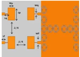
The proposed MIMO antenna design is composed of a four microstrip patch antenna elements. These patch antennas are mounted on a FR4 substrate (εr = 4.4, loss tangent δ = 0.025, and height h = 1.6mm). Patch and substrate dimensions (Lp =11.35mm, Wp = 15.25mm, Lf=6.15mm, Wf=3.05mm, Lq=4.90mm,
Wq=0.50mm&Ls=62.8mm, Ws=60.0mm). Figure-1 and figure-2 shows a simulated and fabricated type-I MIMO antenna. It consist of four symmetrical conventional square patch antennas having smallest edge to edge separation of the four symmetrical elements is (where is the free space wavelength). The ground plane is a defected ground structure (DGS) having a number of complimentary octagon split ring DGS slots (COSRDGSS) windows arranged in H shape.
The unit cell of the proposed COSRDGSS are shown in figure-3 and unit cell dimensions (S1= 4mm,
S2=3.5mm, S3=2.8mm, S4=2.3mm, g=0.30mm,
d=0.845mm&W=0.6mm, L=10mm, W=10mm). Dimensions of the unit cell investigated and optimized for a specific application.
Figure-1 Simulated Type-I MIMO Antenna
Figure-2 Fabricated Type-I MIMO Antenna
Figure-3The unit cell COSRDGSS structure
The type-II proposed MIMO antenna is a modified type-I MIMO antenna. Simulated and fabricated type-II MIMO antenna is shown in figure 4 and figure 5 respectively. It having each side one edge inset slot and dimensions of the slots have been investigated and optimized for specific application. This edge inset slot adds a new set of key parameter to enhance bandwidth and isolation. The ground plane is a defected ground structure (DGS) having COSRDGSs windows are arranged in H shape as like type-I MIMO antenna.
Figure-5 Fabricated Type-II MIMO Antenna
III. EXPERIMENTAL RESULTS
In this section, the proposed type-I MIMO antenna and type-II MIMO antenna presented in the previous sections have been analysed, and investigated.
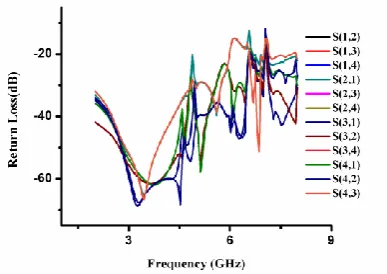
Figure-6 shows the return loss of type-I MIMO antenna. In the case of the type-I MIMO antenna it is clear that, it shows the reflection coefficients S11, S22 S33, and S44 is -17.9dB at 5.9GHz with a frequency bandwidth of 369MHz (C-frequency band) and it supported data rate is 18.14Gbps as per the Shannon channel capacity. Type-I MIMO antenna measured return loss results are in good agreement with simulations.
Figure-6 Return loss of type-I MIMO antenna
Figure-7 shows the return loss of type-II MIMO antenna. In the case of the first MIMO antenna it is clear that, it shows the reflection coefficients S11, S22 S33, and S44 is -20.15dB at 5.9GHz with a frequency bandwidth of 398MHz (C-frequency band) and it supported data rate is 19.56Gbps as per the Shannon channel capacity. Type-II MIMO
antenna measured return loss results are in good agreement with simulations.
Figure-7 Return loss of Type-II MIMO antenna
On other hand due to consequence of separation of inter elements in antenna in order to reducing mutual coupling effect. Due to placement of elements in on substrate there is net flow of current may effect on other element while one port is excited and other ports terminated with the 50 Ω loads. Reducing mutual coupling coefficients (MCC) and to design compact antenna introduced DGS on ground plane. It having a number of complimentary octagonal split ring DGS (COSRDGS) windows arranged in H shape.
Figure-8 shows the mutual coupling coefficient (MCC) of type-I MIMO antenna. MCC between port1 and port 2 are -23.9dB at 5.9GHz resonating frequency.
Figure-8 MCC of Type-I MIMO antenna
port1 and port 2 are -23.78dB at 5.9GHz resonating frequency.
Figure-9 MCC of Type-II MIMO antenna
Figure 10 shows the total peak gain of the type-I MIMO antenna is 4.69dBi and figure 11 shows the total peak gain of type-II MIMO antenna is 4.44dBi. Observing both type-I and type-II MIMO antenna total peak gain, due to edge slot on type-II MIMO antenna has reduced little peak gain as compared to type-I MIMO antenna.
Figure-10 Peak Gain of Type-I MIMO antenna
Figure-11 Peak Gain of Type-II MIMO antenna
The radiation patterns in E-H planes (y-z and x-z
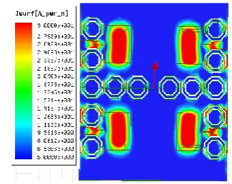
in figure-12 and type-II MIMO antennas shown in figure-13. Figure-14 shows current distribution of type-I MIMO antenna at 5.9GHz resonating frequency. Figure-15 illustrates the current distribution of type-II MIMO antenna at 5.9GHz resonating frequency. Observing current distribution of both type-I, type-II MIMO antenna, type-II MIMO antenna has much stronger due to inset edge slot along with DGS structure.
Figure-12 Radiation Pattern of Type-I MIMO antenna
Figure-15 Surface Current of Type-II MIMO antenna
The proposed type-I MIMO antenna and type-II MIMO antenna results are summarised in table1.
Table 1. Result Summaries Parameters Type-I Return Loss -17.9dB -20.15dB Bandwidth 369MHz 398MHz Data Rate 18.14Gbps 19.56Gbps Mutual Coupling -23.9dB -23.78dB
Gain 4.69dB 4.44dB ground plane it is same as type-I MIMO antenna. In addition, both MIMO antennas fabricated on a FR-4 substrate and their parameters are measured. Measured results are in good agreement with simulations. Proposed antennas are well suitable for 4G and 5G (C-Band) applications.
V.
REFERENCES
[1]. Balanis, C. A . 2009. Antenna Theory: Analysis and
Design. Wiley Publications.
[2]. G. J. Foschini and M. J. Gans, "On limits of wireless communications in a fading environment when
Using multiple antennas," Wireless Personal Commun. vol. 6, pp. 311 -335, 1998.
[3]. T.-Y. Wu, S.-T. Fang, and K.-L. Wong, "Printed diversity monopole antenna for WLAN operation," Electron. Lett., vol. 38, no. 25, pp. 1625-1626, Dec. 2002
[4]. A. Diallo, C. Luxey, P. L. Thuc, R. Staraj, and G. Kossiavas, "Enhanced two-antenna structures for
universal mobile telecommunications system
diversity terminals," IET Microw. Antennas Propag., vol. 1, pp. 93-101, Feb. 2008.
[5]. J. Itoh, N. Michishita, and H. Morishita, "A study on mutual coupling reduction between two inverted-F antennas using mushroom-type EBG structures," in Proc. IEEE Antennas Propag. Soc. Int. Symp.,July. 2008, pp. 1-4.
[6]. M. S. Sharawi, A. B. Numan, M. U. Khan, and D. N.
Aloi, "A Dual-Element Dual-Band MIMO Antenna System with Enhanced Isolation for Mobile Terminals, "IEEE Antennas Wireless Propag. Lett.,vol. 11, pp. 1006-1009, 2012
[7]. Chacko, B.P., Augustin, G., and Denidni, T.A.,
"Uniplanar slot antenna for ultrawideband
polarization -diversity applications,"IEEE Antennas Wireless Propag. Lett., vol. 12, pp. 88-91, 2013
[8]. Thaysen, J., and Jakobsen, K.B, "Envelope
correlation in (N;N) MIMO antenna array from scattering parameters," Microw. Opt. Technol. Lett.,vol. 48, pp. 832-834, 2006.
[9]. L. Liu, S. W. Cheung, and T. I. Yuk, "Compact MIMO antenna for portable devices in UWB Applications," IEEE Trans. Antennas Propag., vol. 61, no. 8, pp. 4257-4264, Aug. 2013.
[10]. FuGuo Zhu, JiaDong Xu, and Qian Xu, "Reduction of M utual Coupling Between Closely-Packed Antenna Elemebnts Using Defected Ground
Structure," IEEE Conference,2009. Antenna