c e-ISSN: 2348-6848, p- ISSN: 2348-795X Volume 2, Issue 11, November 2015
International Journal of Research (IJR)
Available at http://internationaljournalofresearch.orgPositive Sequence Admittance and Negative Sequence
Conductance to Mitigate Voltage Fluctuations in DG systems by
using FUZZY controller with D-STATCOM
Mahaboobunnisa
1& G.PoornachandraRao
21
M. Tech Scholar, Dept of EEE, VBIT, Hyderabad.
[email protected]
2
Asst. Professor, Dept. of EEE, VBIT, Hyderabad.
[email protected]
---***---
ABSTRACT:
In present days, most of the distributed generations depends on renewable energy sources(such as solar or wind) due to its vast advantages. To reduce transmission &distribution costs, network congestion and losses distribution generations (DGs) are connected to micro grids for the distribution of power to the consumers. Increasing the connections of DGs causes voltage fluctuations in the distribution network due to variable output power of DGs with renewable energy sources.Voltage fluctuations are one of the power quality problems and causes severe problems in the power system network such as over loading of transformer, reducing the life time of equipment, sensitive equipment malfunctioning, system losses. This paper presents compensation of voltage fluctuations in DGs using Distributed Static synchronous Compensator (D-STATCOM) with fuzzy logic controller. Tuning control is designed to alleviate the variations of negative and positive sequence voltages whenever the disturbance occurs in the network. The results are verified by simulating the developed method in mat lab environment.
Key Words: Fuzzy Logic Controller; D-STATCOM;
Distributed Generation System; Pulse Width Modulation; etc
I.INTRODUCTION:
Nonconventional energy is consistent and reliable will doubtless be lowest once technology and infrastructure develop. A renewable source includes wind, solar, hydrothermal and geothermal, tidal energy, plus biofuels that are full pledged and harvested without fossil fuels.
Conventional energy, such as petroleum and coal, require rich explorations and doubtless dangerous drilling and mining, and they will become more costly as supplies decrease and demand grownup.
Nonconventional energy produces only minute levels of carbon emissions and as a result helps combat climate change with the usage of fossils. The aggregation of Renewable Energy sources (RES) at the distribution level is termed as Distributed Generation (DG).
Micro grid [1]-[2] may be defined as a collection of distributed generation (DG) units usually connected through power electronic based devices (voltage source inverter¤t source inverter) to the utility grid. DG units can be built with renewable energy sources such as solar energy, fuel cells, hydroelectric power, and wind energy. Small grid can function either linked to the grid or isolated from the grid.
Great penetration of RES reason forissuesinstability, flickering, voltage regulation and power quality of the system.
c e-ISSN: 2348-6848, p- ISSN: 2348-795X Volume 2, Issue 11, November 2015
International Journal of Research (IJR)
Available at http://internationaljournalofresearch.orgAll the FACT devices have its own application. But in case of distribution system D-STATCOM is suitable device to compensate voltage fluctuations, reactive power and harmonics i.e. for all power quality problems DG systems.
D-STATCOM is used in distribution system for reactive power compensation and to control voltage fluctuations as well as to decrease harmonics. D-STATCOM is connected in shunt with transmission lines. In case if we are transmitting sum of power through transmission lines and at receiver end we are getting it with somenoise or any other disturbance that means losses are present in the network. Disturbance may be voltage sag, reactive power and harmonics. Fuzzy logic controller [4]-[6] is extensivelyused in controlling disturbances in power systems. The alternatecontroller known as PI controller is not worthful for many reasons. PI controller includes its incapability to withstand rapid changes in error signal and it is not dynamic in identifying the present error signal. This paper presents the usage of fuzzy logic controller in order to improve the performance of D- STATCOM for Dc-bus voltage control for compensating negative sequence and positive sequence voltages.
Voltage variations are restricted to ±5% as the non conventional energy sources are operated in parallel to systems which are having low voltages as per IEEE Std 1547.2-2008 [7]. A voltage fluctuation indicated by %VUF (Voltage Unbalance Factor) and is kept below 2.0% to 3.0% which is acceptable for both manufacturers and utility, where %VUF is defined as the ratio of the negative-sequence voltage to the positive sequence voltage [8].
2. D-STATCOM OPERATION:
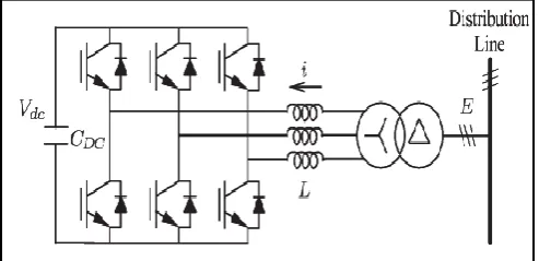
D-STATCOM is being designed with a conventional 3-Ø voltage source inverter and it is coupled to the distribution systems through a boost up transformer and its diagram is as shown in the Fig-1.
Fig -1: power circuit of D-STATCOM
The implemented D-STATCOM operates as fundamental negative-sequence conductance and fundamental positive-sequence admittance as given in eq.1
𝑖∗= 𝑌
𝑝∗. 𝐸𝑓+ ′
+ 𝐺𝑛∗. 𝐸𝑓− ……… (1)
Where 𝑖∗ indicates the reference current, 𝐸𝑓+′ indicates the quadrature fundamental positive-sequence voltage, and 𝐸𝑓− is the fundamental negative-sequence voltage.
Fig -2: reference current generation.
A. REFERENCE-CURRENT GENERATION:
Synchronous Reference Frame (SRF) theory is used to realize the control circuit as shown in Fig. 2. To filter out ripple components, a Low Pass Filter is used to generate the positive-sequence voltage 𝐸𝑞𝑑+𝑒 along with Low Pass Filter a band rejected filter which is tuned at the second-order harmonic frequency is required in order to find out the negative-sequence voltage𝐸𝑞𝑑−𝑒. With the application of reverse transformation, and the negative sequence voltage 𝐸𝑓− and the quadrature fundamental positive-sequence voltage |𝐸𝑓+| in the three-phase system are available, where |𝐸𝑓+′| is lagging behind the fundamental positive-sequence voltage with an angle of 90 degrees. The negative-sequence current command 𝑖𝑓∗−and the positive-sequence current command 𝑖𝑓∗+are equal to product of 𝑌𝑝∗ and |𝐸𝑓+|, product of 𝐺𝑛∗ and |𝐸𝑓−| respectively. Therefore the reference current 𝑖∗ is obtained as shown in the eq.1. For the proper operation of the D-STATCOM fuzzy controller is utilized to generate fundamental current which is in phase with the positive-sequence voltage in order to maintain the voltage of the DC bus Vdc at the reference value of voltage Vdc*.
c e-ISSN: 2348-6848, p- ISSN: 2348-795X Volume 2, Issue 11, November 2015
International Journal of Research (IJR)
Available at http://internationaljournalofresearch.orgFuzzy logic is a intelligent system hence it has numerous applications in different fields such as control engineering, power engineering, medical, control of subway systems, pattern etc. Fuzzy logic controller contains fuzzifier, inference mechanism, defuzzifier to perform the operation. It incorporates simple IF-THEN rules to solve many control system problems rather than attempting a problem in mathematical model. We can get the fuzzy logic controller and fuzzy logic controller with rule viewer blocks in the fuzzy logic tool box. It also allows us to utilize how rules can built at the time of simulation.
C. FUZZY LOGIC TOOLBOX WORKING:
Fuzzy logic tool box provides design of fuzzy logic systems using command line functionality and graphical user interface (GUI) tools. It can also used to build adaptive neuro fuzzy inference systems and fuzzy expert systems. To observe, built and edit fuzzy inference systems in the fuzzy logic tool box five GUI tools are present. They are member ship function editor, surface viewer, FIS editor, rule viewer, rule editor. There are two types of inference methods. They are mamdani&sugeno fuzzy inference method. Mandani is the most common methodology used in all applications.
D. CONTROL OF CURRENT:
Current command is based on the reference current𝑖∗, the current measured i, and the voltage measured is E from Fig-1.The current regulator shown in below
.
Fig-3: Current control loop diagram
Fig-3 produces for space vector pulse width modulation (PWM) control voltage command 𝑣∗ of the inverter. The defined transfer functions 𝐻𝑓 𝑠 and 𝐻ℎ 𝑠 are given as follows
𝐻𝑓 𝑠 = 𝑘𝑝+
2𝐾𝑖,𝑓𝜉𝑤𝑓𝑠
𝑠2+2𝜉 𝑤 ℎ𝑠+𝑤𝑓2
𝐻ℎ 𝑠 =
2𝐾𝑖,ℎ𝜉𝑤ℎ𝑠
𝑠2+2𝜉𝑤 𝑠 + 𝑤2
Where 𝐾𝑝 means proportional gain, the fundamental frequency and its integral gain is 𝑊𝑓 and 𝐾𝑖,𝑓respectively and the harmonic frequency and its integral gain represented as 𝑊ℎ and 𝐾𝑖,ℎrespectively. The damping ratio ξ is used to tune the current regulation to establish a peak of narrowgainintense at the fundamental frequency fortracing of the fundamental current and it will also introducedifferent narrow gain peaks to diminishcurrentdistortion near harmonic frequencies. For the control of parameters 𝑌𝑝∗ and 𝐺𝑛∗Fuzzy logic controller has to be designed.
|𝐸𝑓+|and |𝐸𝑓−| are approximately calculated by using SQRT and Low Pass Filter operation, where Low Pass Filters are considered at cutoff frequency 𝑤𝑐= 10 Hz in order to sort out the ripple components. After that, a Fuzzy controller is designed in order to produce 𝑌𝑝 in order to balance |𝐸𝑓+| at prescribed value |𝐸𝑓+|*. Therefore, Voltages can be maintained at its permissible level with control of𝐺𝑛∗ and imbalanced voltages are suppressed. Here,%VUF (percentage of voltage imbalance factor) is used toindicate the level of imbalanced voltage and it can be defined as the ratio of the negative-sequence voltageto the positive-sequence voltage.
𝐸𝑓+= 𝐸𝑞
+𝑒 𝑡 2+𝐸
𝑑+𝑒 𝑡 2 𝑑𝑡 𝑡+𝑇
𝑡
𝑇
𝐸𝑓−= 𝐸𝑞−𝑒 𝑡 2+𝐸𝑑−𝑒 𝑡 2 𝑑𝑡 𝑡+𝑇
𝑡
𝑇
%VUF= 𝐸𝑓 −
𝐸𝑓+ *100
3. SIMULATION RESULTS AND DISCUSSIONS:
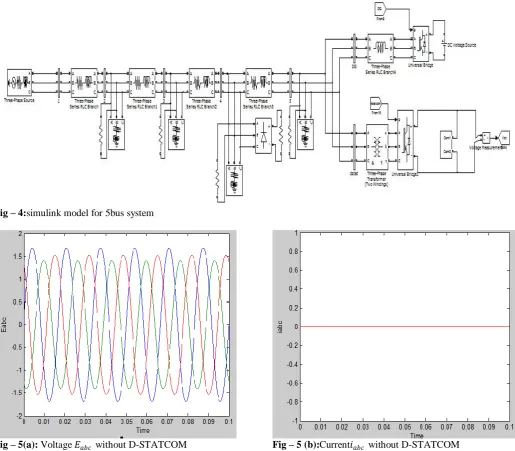
A Power system network rated at 23 KV and 100 MW is designed which is used to illustrate voltage fluctuations and to check the performance of the proposed D-STATCOM.Basicsimulink model for 5bus system for D-STATCOM operation is shown in FIG-4. As the voltage of grid at the end of a lines very much sensitive to the addition of both reactive and real powers depending on the load flow analysis, so the D-STATCOM is installed at the end of the line. Voltage fluctuations are measured in terms of positive sequence voltage 𝐸𝑓+ and voltage unbalalance factor %𝑉𝑈𝐹 . A. STEADY-STATE PERFORMANCE:
c e-ISSN: 2348-6848, p- ISSN: 2348-795X Volume 2, Issue 11, November 2015
International Journal of Research (IJR)
Available at http://internationaljournalofresearch.orgwithout D-STATCOM voltage fluctuations are worst and increases beyond the nominal values ( Ef+ =
1,%VUF=1).
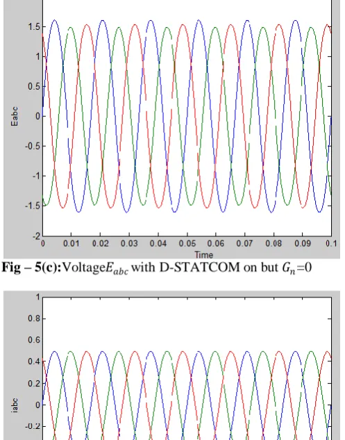
When D-STACOM on with Yp∗=0.37 but Gn∗=0, Ef+ at every bus will maintains nominal value. As there is no compensation of negative sequence voltage %VUF at every bus will be same as in the case of without D-STATCOM shown in Fig-5©&TABLE-2.In this case
D-STACOM with rms currents ia = ib = ic =0.37pu.When D-STATCOM on with Gn∗=9.6pu&Yp∗=0.37pu, it will compensate both Ef+ and %VUF to their nominal values as shown in Fig-5(e)&TABLE-3. In this case rms currents of D-STATCOM are ia=0.52pu,ib=0.25pu,ic=0.35pu.
Fig – 4:simulink model for 5bus system
c e-ISSN: 2348-6848, p- ISSN: 2348-795X Volume 2, Issue 11, November 2015
International Journal of Research (IJR)
Available at http://internationaljournalofresearch.orgFig – 5(c):Voltage𝐸𝑎𝑏𝑐with D-STATCOM on but 𝐺𝑛=0
Fig – 5 (d):Current𝑖𝑎𝑏𝑐with D-STATCOM on but 𝐺𝑛=0
Fig – 5 (e):Voltage𝐸𝑎𝑏𝑐with D-STATCOM on
Fig – 5(f):Current𝑖𝑎𝑏𝑐with D-STATCOM on
TABLE-1: BUS VOLTAGES WHEN D-STACOM OFF
Bus2 Bus3 Bus4 Bus5
𝐸𝑓+ 1 1.02 1.04 1.06 %VUF 1.79 3.753 4.792 5.254
TABLE-2: BUS VOLTAGES WHEN D-STATCOM COMPENSATE
ONLY POSITIVE SEQUENCE VOLTAGE
Bus2 Bus3 Bus4 Bus5
𝐸𝑓+ 1 1 1 1
%VUF 1.79 3.753 4.792 5.254
TABLE-3: BUS VOLTAGES WHEN D-STACOM COMPENSATES BOTH
NEGATIVE AND POSITIVE SEQUENCE VOLTAGE
Bus2 Bus3 Bus4 Bus5
𝐸𝑓+ 1 1 1 1
%VUF 1.703 1.905 2.021 2.021
Fig.-5: Simulation results (a) 𝐸𝑎𝑏𝑐 during D- STATCOM off (b) 𝑖𝑎𝑏𝑐 during D- STATCOM off (c) 𝐸𝑎𝑏𝑐 during D- STATCOM on but 𝐺𝑛∗=0 (d) 𝑖𝑎𝑏𝑐 during D- STATCOM on but 𝐺𝑛∗=0 (e) 𝐸𝑎𝑏𝑐 during D- STATCOM on (f) 𝑖𝑎𝑏𝑐during D- STATCOM on.
B. TRANSIENT OPERATION:
c e-ISSN: 2348-6848, p- ISSN: 2348-795X Volume 2, Issue 11, November 2015
International Journal of Research (IJR)
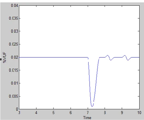
Available at http://internationaljournalofresearch.orgAt t=7s, single phase load is off at bus4 hence %VUF reduces as shown in Fig-6(b).To maintain %VUF at nominal value Gn∗,𝐺𝑛 decreases from 9.6pu as shown in Fig-6(d).
At t=8s, when DG output decreases from 0.9pu to 0.45pu at bus5, Ef+&%VUF are slightly increased and decreased respectively. To maintain voltages at their nominal values 𝑌𝑝 further decreases and 𝐺𝑛 is slightly increased as shown in Fig-6(c)&Fig-6(d).
At t=9s, DG output further decreases from 0.45pu to 0pu interestingly Yp∗ is negative to maintain the fluctuated voltages to nominal values.
Fuzzy logic controller tunes Yp∗andGn∗ accordingly with the variations in the power system network, to maintain the voltages at allowable levels.
Fig – 6(a):Positive sequence voltage |𝐸𝑓+| during transient
period
Fig – 6(b):Voltage Unbalance Factor (%VUF) during transient period
Fig – 6(c):Positive sequence admittance 𝑌𝑝 during transient
period
Fig – 6(d):Negative sequence conductance 𝐺𝑛 during
transient period
4. CONCLUSION:
In this paper, fuzzy logic controller along with negative sequence conductance and positive sequence admittancewas used to control the D-STATCOM which reducesvoltage fluctuations in Distributed Generationsystems. In order to maintain both negative and positivesequence voltages at tolerable level a tuning controlis implemented to dynamically vary conductanceand admittance commands. D-STATCOM operation andits voltage regulation during different situations havebeen discussed. By adjusting conductance and admittancethe operation of DSTATCOM is controlled, thecompromise between the required improvement onpower quality and the D-STATCOM rating can be accomplished.
c e-ISSN: 2348-6848, p- ISSN: 2348-795X Volume 2, Issue 11, November 2015
International Journal of Research (IJR)
Available at http://internationaljournalofresearch.orgusingfuzzy logic controller along with negative sequenceconductance and positive sequence admittance, hence, more Distributed generations can be allowedonline. At last, the D-STATCOM cooperative control has been discussed. The D-STATCOM along SVC and OLTCto control the voltage of the grid by employing a lowfrequencycommunication.
5. REFERENCES
[1] R. Lasseter, “Microgrids,” in Proc. IEEE Power Eng.Soc.Winter Meeting, 2002, pp. 305–308.
[2] F. Katiraei, R. Iravani, N. Hatziargyriou, and A. Dimeas,“Micro grids management,” IEEE Power EnergyMag., vol. 6, no. 3, pp. 54–65,May/Jun. 2008.
[3] C. L. Masters, “Voltage rise: The big issue when connecting embedded generation to long 11 kV over headlines,” Inst. Elect. Eng. Power Eng. J.vol.16, no. 1, pp.5–12, Feb. 2002.
[4]A. AJami and H.S.Hosseini,”Application of Fuzzy Controller for Transient Stability Enhancement of AC Transmission System by STATCOM,”International Joint Conference SICE-ICASE, pp.6059-6063, 2006.
[5]Recently, intelligent controllers like Fuzzy Logic Controllers (FLC) and Artificial Neural Network (ANN) as alternative linear and nonlinear control techniques have been used in control of D-STATCOM.
[6]A. LUO, C. Tang, Z. K. Shuai, J. Tang, X. Y. Xu and D. Chen,”Fuzzy-PI- Based Direct-Output-Voltage control strategy for the STATCOM used in utility distribution systems,”IEEE Trans.Ind.Electron.,vol.56.no.7,July 2009.
[7] IEEE Standard for Interconnecting Distributed Resources with Electric Power Systems, IEEE Std. 1547.2-2008,
.