ISSN (Print) : 2320 – 3765 ISSN (Online): 2278 – 8875
I
nternational
J
ournal of
A
dvanced
R
esearch in
E
lectrical,
E
lectronics and
I
nstrumentation
E
ngineering
(An ISO 3297: 2007 Certified Organization)
Vol. 4, Issue 12, December 2015
A Compact Fuzzy Controller for Sensorless
Direct Torque Controlling of Brushless DC
Motor
Bhanu Pratap Patel
1, Rohit Verma
2PG Student, Dept. of Electrical Engineering, LNCT, Bhopal, M.P, India1
Assistant Professor, Dept. of Electrical Engineering, LNCT, Bhopal, M.P, India2
ABSTRACT: This paper gives a specialized survey of position and speed sensorless routines for controlling brushless direct current (bldc) motor drives, including the foundation investigation utilizing sensors, confinements and advances. the execution and dependability of bldc motor drivers have been enhanced in light of the fact that the routine control and detecting methods have been enhanced through sensorless innovation. at that point, in this paper sensorless advances are audited and late improvements here are presented with their inborn preferences and downsides, including the investigation of reasonable usage issues and applications. the study incorporates a profound review of cutting edge back-emf detecting systems, which incorporates terminal voltage sensing, third harmonic voltage integration, terminal current sensing, back-emf integration and pwm techniques. likewise, the most applicable methods in light of estimation and models are quickly dissected, for example, sliding-mode observer, extended kalman filter, model reference adaptive system, and fuzzy logic controller.
KEYWORDS: BLDC, Back-EMF, Sensorless Position Speed, Estimator, Fuzzy Logic Controller.
I.
INTRODUCTION
For as far back as two decades a few Asian nations, for example, Japan, which have been under weight from high vitality costs, have executed variable speed PM motor drives for vitality sparing applications, for example, aeration and cooling systems and fridges [1]. Then again, the U.S.A. has continued utilizing modest impelling motor drives, which have around 10% lower productivity than customizable PM motor drives for vitality sparing applications. In this way as of late, the increment in vitality costs goads higher requests of variable speed PM motor drives. Additionally, late quick expansion of motor drives into the car business, in view of cross breed drives, creates a genuine interest for high productive PM motor drives, and this was the start of enthusiasm for BLDC motors. BLDC motors, additionally called Permanent Magnet DC Synchronous motors, are one of the motor sorts that have all the more quickly picked up prevalence, primarily in view of their better attributes and execution [2]. These motors are utilized as a part of an extraordinary measure of modern divisions on the grounds that their construction modeling is suitable for any security basic applications. The brushless DC motor is a synchronous electric motor that, from a displaying point of view, looks precisely like a DC motor, having a direct relationship in the middle of current and torque, voltage and rpm. It is an electronically controlled recompense framework, rather than having a mechanical compensation, which is commonplace of brushed motors. Moreover, the electromagnets don't move, the perpetual magnets pivot and the armature stays static. This gets around the issue of how to exchange current to a moving armature.
ISSN (Print) : 2320 – 3765 ISSN (Online): 2278 – 8875
I
nternational
J
ournal of
A
dvanced
R
esearch in
E
lectrical,
E
lectronics and
I
nstrumentation
E
ngineering
(An ISO 3297: 2007 Certified Organization)
Vol. 4, Issue 12, December 2015
expense of impelling gadgets, sensorless control procedures are ordinarily utilized. The benefit of sensorless BLDC motor control is that the detecting part can be overlooked, and in this way general expenses can be extensively lessened. The disservices of sensorless control are higher necessities for control calculations and more confounded hardware [3]. The majority of the electrical motors that don't require an electrical association (made with brushes) in the middle of stationary and pivoting parts can be considered as brushless changeless magnet (PM) machines [4], which can be classified taking into account the PMs mounting and the back-EMF shape. The PMs can be surface mounted on the rotor (SMPM) or introduced within the rotor (IPM) [5], and the back-EMF shape can either be sinusoidal or trapezoidal. As per the back-EMF shape, PM AC synchronous motors (PMAC or PMSM) have sinusoidal back-EMF and Brushless DC motors (BLDC or BPM) have trapezoidal back-EMF. A PMAC motor is regularly energized by a three-stage sinusoidal current, and a BLDC motor is normally fueled by an arrangement of streams having a semi square waveform [6,7].
II.
REVIEW OF ADVANCES IN SENSORLESS CONTROL TECHNIQUES
Position sensors can be totally wiped out, along these lines diminishing further cost and size of motor gathering, in those applications in which just variable speed control (i.e., no positioning) is obliged and framework flow is not especially requesting (i.e., gradually or, at any rate, typically differing burden). Truth be told, some control techniques, for example, back-EMF and current detecting, give, as a rule, enough data to assess with adequate exactness the rotor position and, thusly, to work the motor with synchronous stage streams. A PM brushless drive that does not oblige position sensors but rather just electrical estimations is known as a sensorless drive [4]. The BLDC motor gives an alluring contender to sensorless operation on the grounds that the way of its excitation intrinsically offers a minimal effort approach to concentrate rotor position data from motor-terminal voltages. In the excitation of a three-stage BLDC motor, with the exception of the stage compensation periods, just two of the three stage windings are leading at once and the no directing stage conveys the back-EMF. There are numerous classifications of sensorless control methods [6]; nonetheless, the most famous class is taking into account back electromotive powers or back-EMFs [7]. Detecting back-EMF of unused stage is the most cost effective technique to get the substitution succession in star injury motors. Since back-EMF is zero at stop and corresponding to speed, the deliberate terminal voltage that has extensive sign to-commotion proportion can't identify zero intersection at low speeds. That is the motivation behind why in all back-EMF-based sensorless strategies the low-speed execution is restricted, and an open-circle beginning system is obliged [8].
For the most part, a brushless DC motor comprises of a changeless magnet synchronous motor that changes over electrical vitality to mechanical vitality, an inverter relating to brushes and commutators, and a pole position sensor [19], as Figure shows. The stator iron of the BLDC motor has a non-straight attractive immersion trademark, which is the premise from which it is conceivable to focus the starting position of the rotor. At the point when the stator winding is invigorated, applying a DC voltage for a sure time, an attractive field with a settled course will be set up. At that point, the present reactions are distinctive because of the inductance contrast, and this variety of the present reactions contains the data of the rotor position [20]. Accordingly, the inductance of stator winding is an element of the rotor position.
ISSN (Print) : 2320 – 3765 ISSN (Online): 2278 – 8875
I
nternational
J
ournal of
A
dvanced
R
esearch in
E
lectrical,
E
lectronics and
I
nstrumentation
E
ngineering
(An ISO 3297: 2007 Certified Organization)
Vol. 4, Issue 12, December 2015
III.
EXTENDED KALMAN FILTER (EKF)
The expanded Kalman filter calculation is an ideal recursive estimation calculation for nonlinear frameworks. It forms every accessible estimation paying little heed to their exactness, to give a fast and precise appraisal of the variables of interest, furthermore accomplishes a quick union. This is done utilizing the accompanying components: the learning of the framework flow, measurable depiction of the framework lapses (clamors, aggravations, and so on.), and data about the beginning states of the variables of premium. The calculation is computationally serious, in this manner an effective plan is required as opposed to a direct execution. Besides, for a down to earth utilization of the filter continuously, diverse parts of usage must be tended to, for example, the computational necessities (handling time per filter cycle, obliged memory stockpiling, and so forth.) and the PC limitations (cycle execution time, guideline set, number juggling utilized, and so forth.) [6]. this strategy can be utilized to appraise the rotor position and speed. Motor state variables are evaluated by method for estimations of stator line voltages and streams, and applying EKF next. Amid this procedure, voltage and current measuring signs are not filtered, and rotor position and speed can be assessed with adequate exactness in both relentless state and element operations [2]. Dissimilar to the deterministic base of different studies, the model instabilities and nonlinearities in motors are appropriate to the stochastic way of EKFs, and in addition the persistency of excitation because of the framework and estimation clamors. This is the motivation behind why the EKF has discovered wide application in speed-sensorless control, disregarding its computational intricacy. Be that as it may, with the improvements in elite processor innovation, the computational weight and speed of EKF has stopped to be an issue [5]. The square chart of the framework for speed and rotor position estimation of a BLDC motor is indicated in Figure 2. The framework can be practically separated in two essential parts: the speed control framework and the estimation framework. The first comprises of a force circuit (DC supply, inverter and motor) and control circuits, which perform three capacities: current recompense, current control and speed control. The deliberate speed (ω k) and stage streams (ik) and also the evaluated rotor position (θ ^k/k ) are utilized as criticism signs. The primary pieces of the estimation calculation are the EKF and the square for computing normal motor line voltages amid inspecting time. The normal line voltages vector, characterized on the premise of normal line voltages in the k-inspecting time (u k), is computed toward the start of the examining time by method for terminal voltages to unbiased point vector (u Nk ), the inverter transistors obligation cycle (є k ), the inverter DC voltage (U 0 ), the assessed speed (ω ^k/k ), the rotor position (θ ^k/k ), and measured streams vector (i k ).
Figure 2. System configuration for speed and rotor position estimation of a BLDCM [6].
ISSN (Print) : 2320 – 3765 ISSN (Online): 2278 – 8875
I
nternational
J
ournal of
A
dvanced
R
esearch in
E
lectrical,
E
lectronics and
I
nstrumentation
E
ngineering
(An ISO 3297: 2007 Certified Organization)
Vol. 4, Issue 12, December 2015
IV.
FUZZY LOGIC CONTROLLER
Fuzzy logic is an approach to computer science that mimics the way a humanbrain thinks and solves problems [11]. Theidea of fuzzy logic is to approximatedecision making using naturallanguage terms instead of quantitative terms. It is generally considered as modeling of information where it cannot bedefined precisely, but some broad definitions can be formed. Because of its simplicity and effectiveness, Fuzzy-logic technology has gained many applications in scientific and industrial applications.
A typical architecture of FLC is shown below, which comprises of four principal comprises: a fuzzifier, a fuzzy rule base, inference engine, and a defuzzifier.
Fuzzifier:Used to transform crisp measured data (e.g. speed is 10 mph) into suitable linguistic values (i.e. fuzzy sets,
for example, speed is too slow).
Fuzzy Rule Base: stores the empirical knowledge of the operation of the process of the domain experts.
Inference Engine: is the kernel of a FLC, and it has the capability of simulating human decision making by performing approximate reasoning to achieve a desired control strategy.
Defuzzifier: is utilized to yield a nonfuzzy decision or control action from an inferred fuzzy control action by the
inference engine.
Figure 3: Block Diagram of Fuzzy Controller
V.
MODELING OF BLDC
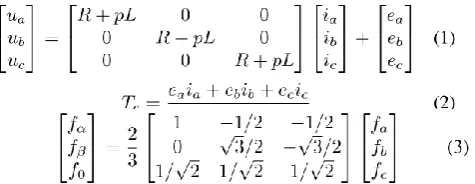
The BLDC is demonstrated in the stationary reference casing utilizing stage streams, speed, and rotor position as state variables. As the stator winding unbiased point is not available, which makes it difficult to specifically measure stage voltages, it is important to define a BLDCM model with line voltages as info variables. On the premise of the BLDCM model with stage voltages, the accompanying model has been determine.
Where ua,ub,uc, ia,ib,ic and ea, eb, ec are phase stator voltages, stator currents and back-EMFs respectively, R and L are the stator phase winding resistance and phase inductance, Te is the electromagnetic torque, ω is the rotor speed in angular frequency, p is the differential operator (d/dt). With the transformation in (3) and (4), the equations (1) and (2) can be transformed to the stationary frame.
ISSN (Print) : 2320 – 3765 ISSN (Online): 2278 – 8875
I
nternational
J
ournal of
A
dvanced
R
esearch in
E
lectrical,
E
lectronics and
I
nstrumentation
E
ngineering
(An ISO 3297: 2007 Certified Organization)
Vol. 4, Issue 12, December 2015
Where f represents the voltage, current and back EMF.The mathematical model of a BLDC drive can be describedby the following equations in a stationary frame as[3].
Where uα, uβ, iα, iβ and eαeβ are the αβ-axis rotor fluxlinkages, rotor stator voltages, rotor stator currents and back-EMFs respectively.
VI.
IMPLEMENTATION OF THE MODEL
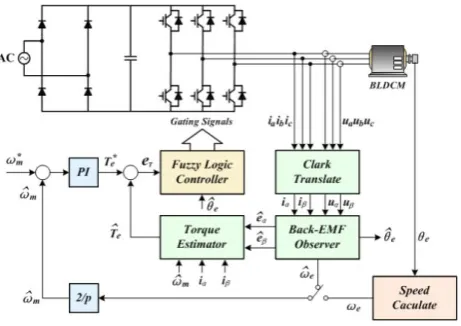
The piece chart of a sensorless BLDC drive with fluffy DTC may be as indicated in Fig, 4. In the proposed framework, there are the inward torque circle and external speed circle. The principle parts of the framework are speed PI controller, fluffy rationale controller, clark interpretation, back-EMF eyewitness and torque estimator and so on.. The reference torque is acquired from the speed controller and is restricted at a sure esteem. Stator currents (ia, ib, ic) and voltages (Va, Vb, Vc) are measured and after that changed into the stationary reference outline alpha and beta parts in
the framework.
Figure 4. Block diagram of the proposed control system
As portrayed over, a back-EMF spectator gives the assessed back-EMF. The rotor position, rotor speed and the torque are computed from appraisals of the back-EMF. A fluffy rationale controller creates the substitution signs taking into account the mistake between the reference and assessed torque. It is likewise seen that the DTC plan for BLDC is autonomous of motor parameters aside from the stator resistance and inductance, which influences just the low-speed execution of the drive and can be adjusted.
VII.
SIMULATION AND RESULTS ANALYSIS
ISSN (Print) : 2320 – 3765 ISSN (Online): 2278 – 8875
I
nternational
J
ournal of
A
dvanced
R
esearch in
E
lectrical,
E
lectronics and
I
nstrumentation
E
ngineering
(An ISO 3297: 2007 Certified Organization)
ISSN (Print) : 2320 – 3765 ISSN (Online): 2278 – 8875
I
nternational
J
ournal of
A
dvanced
R
esearch in
E
lectrical,
E
lectronics and
I
nstrumentation
E
ngineering
(An ISO 3297: 2007 Certified Organization)
Vol. 4, Issue 12, December 2015
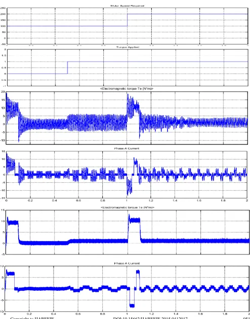
generated by previous and proposed technique.
Figure4 shows the performance comparison between the previous method using and the proposedmethod. The torque ripple and the current ripple are much less, compared with the previous scheme.
Figure 5: shows the required speed, applied torque and the Actual Speed Achieved by the motor using previous and proposed technique.
The results in figure shows that the previous fails in controlling of motor much before the proposed technique.
VIII.
CONCLUSION
In this paper, a novel sensorless Fuzzy-DTC for BLDC motors was proposed to accomplish torque swell decrease. The plan disposes of the flux linkage control and just has the torque control in the framework. Fluffy rationale control is connected to the framework, which appropriately fuzzify the torque lapse and rotor position into a few subsets to precisely select the voltage space vector. Considering the torque, the rotor position and speed of BLDC are difficult to ascertain specifically, a state spectator is intended to get the back-EMF, then, the torque, the rotor position and speed can be figure from back-EMF effectively. The reproduction results demonstrate that the proposed plan has great estimation execution in low and rapid extent and great control execution, contrasted and the PWM technique.
REFERENCES
ISSN (Print) : 2320 – 3765 ISSN (Online): 2278 – 8875
I
nternational
J
ournal of
A
dvanced
R
esearch in
E
lectrical,
E
lectronics and
I
nstrumentation
E
ngineering
(An ISO 3297: 2007 Certified Organization)
Vol. 4, Issue 12, December 2015
3. Hubik, V.; Sveda, M.; Singule, V. On the Development of BLDC Motor Control Run-Up Algorithms for Aerospace Application. In Proceedings of the 13th Power Electronics and Motion Control Conference (EPE-PEMC 2008), Poznan, Poland, September 2008; pp. 1620-1624. 4.Bonfe, M.; Bergo, M. A Brushless Motor Drive with Sensorless Control for Commercial Vehicle Hydraulic Pumps. In Proceedings of the IEEE International Symposium on Industrial Electronics (ISIE 2008), Cambridge, England, July 2008; pp. 612-617.
5. Bianchi, N.; Bolognani, S.; Jang, J.H.; Sul, S.K. Comparison of PM Motor Structures and Sensorless Control Techniques for Zero-Speed Rotor Position Detection. IEEE Trans. Power Electron. 2007, 22, 2466-2475.
6. Su, G.J.; McKeever, J.W. Low-Cost Sensorless Control of Brushless DC Motors with Improved Speed Range. IEEE Trans. Power Electron. 2004, 19, 296-302.
7. Damodharan, P.; Vasudevan, K. Indirect Back-EMF Zero Crossing Detection for Sensorless BLDC Motor Operation. In Proceedings of the International Conference on Power Electronics and Drives Systems (PEDS 2005), Kuala Lumpur, Malaysia, November 2008; pp. 1107-1111. 8. Naidu, M.; Nehl, T.W.; Gopalakrishnan, S.; Wurth, L. Keeping Cool while Saving Space and Money: A Semi-Integrated, Sensorless PM Brushless Drive for a 42-V Automotive HVAC Compressor. IEEE Ind. Appl. Mag. 2005, 11, 20-28.
9. Brushless DC Motor Control using the LPC2141 Application Note; AN10661, NXP Semiconductors: Eindhoven, the Netherlands, October 2007.
10. Brushless DC (BLDC) Motor Fundamentals Application Note; AN885, Microchip: AZ, USA. 2003.
11. Burger, F.; Besse, P.A.; Popovic, R.S. New Single Chip Hall Sensor for Three Phases Brushless Motor Control. Sens. Actuat. A-Phys. 2000, 81, 320-323.

![Figure 2. System configuration for speed and rotor position estimation of a BLDCM [6]](https://thumb-us.123doks.com/thumbv2/123dok_us/7781958.1285790/3.595.189.427.512.646/figure-configuration-speed-rotor-position-estimation-bldcm.webp)