Series Compensation to Mitigate Voltage Sag
and Transient Stability Analysis by Using
SVC of 11- Bus System
Pankaj Kumar1, Ankit Sachan1, Dr. Pankaj Rai2
Research Scholar, Department of Electrical Engineering, IIT (BHU) Varanasi, Varanasi, U.P., India1
Associate Professor, Department of Electrical Engineering, B.I.T. Sindri, Sindri, Jharkhand, India2
ABSTRACT: Power system stability is defined as the ability of power system to preserve its steady stability or recover the initial steady state after any deviation of the system’s operation. Present time power systems are being operated nearer to their stability limits due to economic and environmental reasons. Maintaining a stable and secure operation of a power system is therefore a very important and challenging issue. Transient stability has been given much attention by power system researchers and planners in recent years, and is being regarded as one of the major sources of power system insecurity. Shunt FACTS devices play an important role in improving the transient stability, increasing transmission capacity and damping low frequency oscillations. In this work 11-bus power system network has been modeled using MATLAB SIMULINK software. The power system network under study consist of three units of power plant each producing 20 KV and step up by two winding transformer to 230 KV. For parallel operation of three different power plants, the frequency and the terminal voltage has been kept constant to avoid circulating current in the existing network. A Static VAR Compensator and a series compensator have been used in the considered network for improving the transient stability and to increase the transmission capacity of the system.
KEYWORDS: Power System Stability, Transient Stability, SVC, Series Compensator.
I. INTRODUCTION
Power systems generally consist of three stages: generation, transmission, and distribution. In the first stage, generation, the electric power is generated mostly by using synchronous generators. Then the voltage level is raised by transformers before the power is transmitted in order to reduce the line currents which consequently reduce the power transmission losses. After the transmission, the voltage is stepped down using transformers in order to be distributed accordingly. Power systems are designed to provide continuous power supply that maintains voltage stability. However, due to undesired events, such as lightning, accidents or any other unpredictable events, short circuits between the phase wires of the transmission lines or between a phase wire and the ground which may occur is called a fault. Due to occurring of a fault, one or more generators may be severely disturbed causing an imbalance between generation and demand. If the fault persists and is not cleared in a pre-specified time frame, it may cause severe damages to the equipment’s which in turn may lead to a power loss and power outage. Therefore, protective equipment’s are installed to detect faults and clear/isolate faulted parts of the power system as quickly as possible before the fault energy is propagated to the rest of the system.
FACTS to power system stability in particular have been carried out using same databases. It was found that the ratio of FACTS applications to the stability study with respect to other power system studies is more than 60% in general.
II. CLASSIFICATION OF STABILITY
Fig.1 provides a comprehensive categorization of power system stability. As Depicted by Fig. 1, there are two main classes of stability: rotor angle stability and voltage stability. Rotor angle stability has two main subclasses: small-disturbance angle (steady-state) stability and transient stability. A power system is considered to be steady-state stable if, after any small disturbance, it reaches a steady state operating condition which is identical or close to the pre disturbance operating condition. A power system is transient stable for a large disturbance or sequence of disturbances if, following that disturbances it reaches an acceptable steady-state operating condition. Unlike steady-state stability which is a function only of the operating condition, transient stability is more complicated since it is a function of both operating condition and the disturbance [2]. Voltage stability also has two main subclasses: large disturbance voltage stability and small disturbance voltage stability.
Fig.1. Classification of power system stability
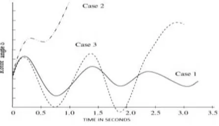
Transient stability is the ability of the power system to maintain synchronism when subjected to sever transient disturbance. The response to this type of disturbance involves large excursions of rotor angles and is influenced by nonlinear power-angle relationship. Stability depends on the initial operating state of the system and the severity of the disturbance. The system usually altered after the disturbance which may cause the system to operate in a different steady-state status from that prior the disturbance. Power systems are designed to be stable for a selected set of contingencies. The contingencies usually considered are short-circuits of different types: phase-to-ground, phase-to phase- to-ground, or three-phase. They are usually assumed to occur on the transmission lines, but occasionally bus or transformer faults are also considered. Methods of transient stability analysis comprising as swing equation, Equal area criterion, Numerical Integration Methods, Direct Methods Transient Stability Analysis.
Fig.2. Rotor angle response to a transient disturbance.
becomes unstable as a result of growing oscillations as the end state is approached. This form of instability occurs when the post fault steady-state condition is itself is small signal unstable. In transient stability studies, the study period of interest is usually limited to 3 to 5 seconds following the disturbance, although it may extend to about ten seconds for very large systems with dominant inter area modes of oscillation.
III. STATIC VAR COMPENSATOR (SVC)
The Static Var Compensator (SVC) is a shunt device of the Flexible AC Transmission Systems (FACTS) family using power electronics to control power flow and improve transient stability on power grids [1]. The SVC regulates voltage at its terminals by controlling the amount of reactive power injected into or absorbed from the power system. When system voltage is low, the SVC generates reactive power (SVC capacitive). When system voltage is high, it absorbs reactive power (SVC inductive). The variation of reactive power is performed by switching three-phase capacitor banks and inductor banks connected on the secondary side of a coupling transformer. Each capacitor bank is switched on and off by three thyristor switches (Thyristor Switched Capacitor or TSC). Reactors are either switched on-off (Thyristor Switched Reactor or TSR) or phase-controlled (Thyristor Controlled Reactor or TCR). It is a variable impedance device where the current through a reactor is controlled using back to back connected thyristor valves. The application of thyristor valve technology to SVC is an offshoot of the developments in HVDC technology. The major difference is that thyristor valves used in SVC are rated for lower voltages as the SVC is connected to an EHV line through a step down transformer or connected to the tertiary winding of a power transformer. The application of SVC was initially for load compensation of fast changing loads such as steel mills and arc furnaces. Here the objective is to provide dynamic power factor improvement and also balance the currents on the source side whenever required. The application for transmission line compensators commenced in the late seventies. Here the objectives are to Increase power transfer in long lines, improve stability with fast acting voltage regulation, damp low frequency oscillations due to swing (rotor) modes, damp sub synchronous frequency oscillations due to torsional modes, control dynamic over voltage. The SVC is configured in two ways (i) Fixed Capacitor-Thyristor Controlled Reactor (FCTCR) (ii) Thyristor Switched Capacitor (TSC-TCR).
Fig.3. A Typical SVC (TSC-TCR) Configuration
The second type is more flexible than the first one and requires smaller rating of the reactor and consequently generates fewer harmonic. The schematic diagram of a TSC-TCR type SVC is shown in Fig.3, this shows that the TCR and TSC are connected on the secondary side of a step-down transformer. Tuned and high pass filters are also connected in parallel which provide capacitive reactive power at fundamental frequency. The voltage signal is taken from the high voltage SVC bus using a potential transformer.
SVC are much less than the voltage ratings of a HVDC valve as a step down transformer is used in the case of SVC. To limit in a TSC it is necessary to provide a small reactor in series with the capacitor.
The block diagram of basic SVC Controller incorporating voltage regulator is shown in Fig.4, This shows that both voltage (Vsvc) and current (Isvc) signals are obtained from potential and current transformers and then rectified.
Fig.4. SVC Controller
The AC filter is basically a notch filter to eliminate the signal component of frequency corresponding to the parallel resonance in the system viewed from the SVC bus. The line capacitance (in parallel with SVC capacitance) can result in parallel resonance with the line inductance. The SVC voltage regulator has a tendency to destabilize this resonant mode of oscillation and the notch filter is aimed at overcoming this problem. As a matter of fact, any parallel resonance mode (of frequency below second harmonic) can have adverse interaction with SVC voltage regulator.. If series capacitors are used along with SVC, then they can cause parallel resonance with a neighboring shunt reactor. If the second (parallel resonance) mode has a lower frequency (say below 20 Hz), a high pass filter in addition to the notch filter has been suggested The rectified signal is filtered. The DC side filters include both a low pass filter (to remove the ripple content) and notch filters tuned to the fundamental and second harmonic components The notch filters are provided to avoid the adverse interactions of SVC caused by second harmonic positive sequence and fundamental frequency negative sequence voltages on the SVC bus. For example, second harmonic positive sequence voltages at the SVC bus cause a fundamental frequency component in the rectified signal that results in the modulation of SVC susceptance at the same frequency. This in turn (due to amplitude modulation) results in two components at side band frequencies (0,2f) in the SVC current. The dc component can result in unsymmetric saturation of the SVC transformer and consequent increase in the magnetization current containing even harmonics. It has been observed that this adverse harmonic interaction between the SVC and the network can result in large distortion of the SVC bus voltage and impaired. Distortion of the SVC bus distortion of the SVC bus voltage and impaired operation of SVC (termed as second harmonic instability). The auxiliary signals mentioned in Fig.3 are outputs from the susceptance (or reactive power) Regulator (SR) and Supplementary Modulation Controller (SMC). The Susceptance Regulator is aimed at regulating the output of SVC in steady state such that the full dynamic range is available during transient disturbances. The output of Susceptance Regulator modifies the voltage reference in steady state. However its operation is deliberately made slow such that it does not affect the voltage regulator function during transients.
IV. SERIES COMPENSATOR
Fig.5. Series Compensation of Subsystem
The capacitor is protected by the MOV block. A gap is also connected in parallel with the MOV block. The gap is fired when the energy absorbed by the surge arrester exceeds a critical value of 30 MJ. To limit the rate of rise of capacitor current when the gap is fired, a damping RL circuit is connected in series. Open the Energy & Gap firing subsystem. It shows how you calculate the energy dissipated in the MOV by integrating the power (product of the MOV voltage and current). When the energy exceeds the 30 MJ thresholds, a closing order is sent to the Breaker block simulating the gap.
V. SIMULATION AND RESULTS
In this paper three plants has been considered of 900 MW each generating 20 KV and then fed to two winding
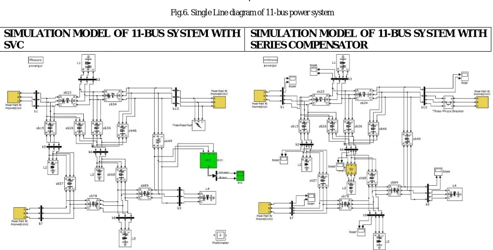
Fig.6. Single Line diagram of 11-bus power system
SIMULATION MODEL OF 11-BUS SYSTEM WITH SVC
SIMULATION MODEL OF 11-BUS SYSTEM WITH SERIES COMPENSATOR
transformers where voltage is step up to 230 KV and then connected to the transmission system which consist of 11buses. There are five loads connected in the buses 3,5,6,8 and 9 respectively. Simulation model has been developed using MATLAB SIMULINK software. A three phase fault has been created near bus no 10 for time 0.01 to 0.03 sec and its impact has been taken down with the help of different bus scopes connected in the model. In the same system i have introduced a series compensator which is 55 % compensated near bus no. 6 to reduce the overshoot caused due to fault and see the amount of overvoltage and over current reduced by the use of it. The system is modeled without and with SVC to observe the phenomena of transient oscillation and subsequently how it is damped out by the SVC. It is found that the SVC can effectively damp out the resulting oscillating. In the result part we have compared the outputs of two models with and without SVC. Thus it has been clearly observed that the transient oscillations sustain up to 0.03 sec without SVC and with the use of SVC the transient oscillation vanishes before 0.01 sec. Further it has been observed that with use of series compensator the fault amplitude for current and voltages at different buses reduces and transmission capacity increases thus improving the power transfer capability.
Fig.9. Voltage Waveform of 10 Bus Systems (a).without SVC (b) with SVC
Fig.10. Voltage Waveform of 9 Bus Systems (a) without SVC (b) with SVC
Fig.12. Current Waveform of 9 Bus Systems (a) without SVC (b) without SVC
Fig.13. Voltage Waveform of 1 Bus System (a) without Compensator (b) with Compensator
Fig.14. Voltage Waveform of 2Bus Systems (a) without Compensator (b) with Compensator
VI. CONCLUSION
The system is modeled without and with SVC to observe the phenomena of transient oscillation and subsequently how it is damped out by the SVC. It is found that the SVC can effectively damp out the resulting oscillating. In the result part we have compared the outputs of two models with and without SVC. Thus it has been clearly observed that the transient oscillations sustain up to 0.03 sec without SVC and with the use of SVC the transient oscillation vanishes before 0.01 sec. Further it has been observed that with use of series compensator the fault amplitude for current and voltages at different buses reduces and transmission capacity increases thus improving the power transfer capability.
REFERENCES
[1.] L. Gyugyi, “Reactive Power Generation and Control by Thyristor Circuits" IEEE Trans., v. IA-15, n.5, 1979, pp.521531
[2.] A.Olwegard et al, “Improvement of Transmission Capacity by Thyristor Controlled Reactive Power", IEEE Trans .v. PAS100, 1981, pp. .3930-3939.
[3.] R.M. Mathur, Editor, Static Compensators for Reactive Power Control, Canadian Electrical Association, Cantext Publications, Winnipeg, 1984 [4.] A. E. Hammad, “Analysis of power system stability enhancement by static var compensators”, IEEE Trans. On Power Systems, vol. 1, No. 4, pp.
[5.] M. O'Brien and G.Ledwich, “Static Reactive Power Compensator Controls for Improved System Stability", IEEE Proc., v.134, Pt.c, n.1, 1987, pp.38-42
[6.] L. Gyugyi, “Power Electronics in Electric Utilities : Static Var Compensators” in Proc. IEEE’ 76, paper 4, p. 483–494, 1988.
[7.] K. R. Padiyar and R.K.Varma, “Concepts of Static Var System Control for Enhancing Power Transfer in Long Transmission Lines", Electric machines and Power Systems, v.18, 1990, pp.337-358
[8.] K. R. Padiyar, and R. K. Verma, “Concepts Of Static VAR System Control For Enhancing Power Transfer In Long Transmission Lines”, Electric Machines and Power Systems, vol. 18, p. 337-358, 1990.
[9.] K. R. Padiyar and R.K. Varma,”Damping Torque Analysis of Static Var System controller ", IEEE Trans., Power Systems, v.6, n.2, 1991, pp.458-465
[10.]P. Kundur, Power System Stability and Control, EPRI Power System Engineering Series, New York, McGraw-Hill Inc, 1994.
[11.]V. Rajkumar and R. R. Mohler , “Nonlinear control methods for power systems : A comparison", IEEE Trans. on Control Systems Technology, v. 3, n. 2, 1995, pp. 231-237.
[12.] V. Venkatasubramanian , K.W. Schneider and C.W. Taylor, “ Improving Pacific intertie stability using existing static VAR compensators and Thyristor Controlled Series Compensation", Bulk Power System Dynamics and Control IV { Restructuring, Santorini, Greece, August
[13.]N. G. Hingorani, and L. Gyugyi, Understanding FACTS, Concept and Technology of Flexible AC Transmission Systems, New York, Wiley Publishers, 2000.
[14.] H. Saadat, Power System Analysis, Tata McGraw-Hill, 2002.
[15.]G. Sybille and P. Giroux, ” Simulation of FACTS Controllers using the MATLAB Power System Blockset and Hypersim Real-Time Simulation”,
IEEE PES, Panel Session Digital Simulation of FACTS and Custom-Power Controllers Winter Meeting, New York, p. 488– 49, 2002.
[16.] M. H. Hague, “Improvement of first stability limit by utilizing full benefit of shunt FACTS devices”, IEEE Transactions On Power Systems, vol. 19, no.4, pp. 1894 – 1902, 2004.
[17.] IEEE TASK FORCE: ‟ Proposed Terms and Definitions for Flexible AC Transmission, vol.12, No.4, Systems (FACTS)”, IEEE Trans. On Power Delivery 2005.
[18.]S. Panda, and Ramnarayan M. Patel, “Improving Power System Transient Stability with an. Off–Centre Location of Shunt Facts Devices ”, Journal of Electrical Engineering, vol. 57, No. 6, 2006
[19.]K. R. Padiyar, FACTS Controllers in Power Transmission and Distribution, New Age International Publishers, 2007.
[20.]A. Ghosh, D. Chatterjee, "Transient Stability Assessment of Power Systems Containing and Shunt Compensators", Power Systems, IEEE Transactions on Power Delivery, vol. 22, no.3, p. Series 1210-1220, Aug. 2007.
[21.]A. A. Edris, R. Aapa, M. H. Baker, L. Bohman and K. Clark, “Proposed Terms and Definitions for Flexible Ac Transmission Systems (FACTS)”, IEEE Trans. On Power