IJEDR1402136
International Journal of Engineering Development and Research (www.ijedr.org)2134
Optimal Reactive Power Dispatch
(ORPD) Using Generalized Differential Evolution
Algorithm
1
Arvindkumar J. Bhakta,
2Prof. Shabbir H. Ghadiali
1Master of Engineering, 2Associate Professor & HEAD T&P
Department of Electrical
Sarvajanik College of Engineering and Technology, surat
1[email protected], 2[email protected]
_______________________________________________________________________________________________________
Abstract— Optimal Reactive Power Dispatch (ORPD) is required for power system control and proper operation. ORPD
reduces the power system losses and improves the voltage profile, power system security, power transmission capability and overall system operation. The reactive power control variables like generator voltage, transformer tap-settings and switchable VAR sources are adjusted to solve ORPD problem. In this paper, the ORPD problem is solved as nonlinear constrained optimization problem with equality and inequality constraints for minimization of power losses and voltage deviation. The proposed approach employs Matpower Optimization toolbox of Matlab for the optimal setting of ORPD control variables. The Matpower Optimization toolbox has been implemented using generalized differential evolution on a standard IEEE 30-bus system to minimize power losses and voltage deviation. The simulation results of the proposed approach are compared with the results obtained from particle swarm optimization (PSO) based algorithm.
Keywords—Load Flow, Loss Minimization, Voltage Profile Improvement, Reactive power dispatch, Differential Evolution,
Penalty function
________________________________________________________________________________________________________
I. INTRODUCTION
The purpose of the reactive power dispatch (RPD) in power system is to identify the control variables which minimize the given objective function while satisfying the unit and system constraints. This goal is achieved by proper adjustment of reactive power variables like generator voltage magnitudes, switchable VAR sources and transformer tap setting [1].
In the past two decades, the problem of RPD for improving economy and security of power system operation has received much attention. The main objective of optimal reactive power control is to improve the voltage profile and minimizing system real power losses via redistribution of reactive power in the system. In addition, the voltage stability can be enhanced by reallocating reactive power generations. Therefore, the problem of the RPD can be optimized to enhance the voltage stability, improve voltage profile and minimize the system losses as well [2–4].
To solve the RPD problem, a number of conventional optimization techniques [5,6] have been proposed. These include the Gradient method, Non-linear Programming (NLP), Quadratic Programming (QP), Linear programming (LP) and Interior point method. Though these techniques have been successfully applied for solving the reactive power dispatch problem, still some difficulties are associated with them. One of the difficulties is the multimodal characteristic of the problems to be handled. Also, due to the non-differential, non-linearity and non-convex nature of the RPD problem, majority of the techniques converge to a local optimum. Recently, Evolutionary Computation techniques like Genetic Algorithm (GA) [7], Evolutionary Programming (EP) [8] and Evolutionary Strategy [9] have been applied to solve the optimal dispatch problem. In this paper, a new evolutionary computation technique, called Differential Evolution (DE) algorithm is used to solve RPD problem.
Recently, differential evolution (DE) algorithm has been proposed and introduced [10–13]. The algorithm is inspired by biological and sociological motivations and can take care of optimality on rough, discontinuous and multi-modal surfaces. The DE has three main advantages: it can find near optimal solution regardless the initial parameter values, its convergence is fast and it uses few number of control parameters. In addition, DE is simple in coding and easy to use. It can handle integer and discrete optimization [10–13].
IJEDR1402136
International Journal of Engineering Development and Research (www.ijedr.org)2135
In [21–23], the DE algorithm is used as an optimization tool for the reactive power optimization with propose of minimizing the system power losses while maintaining the dependant variables including voltages of PQ-buses and reactive power outputs of generators, within limits. In [24], the DE algorithm is used to solve reactive power dispatch for voltage stability enhancement.In this paper, a novel DE-based approach is proposed to solve the RPD problem. The problem is formulated as a nonlinear optimization problem with equality and inequality constraints. In this study, different objectives are considered such as minimizing the power losses, improving the voltage profile, and enhancing power system voltage stability. The proposed approach has been examined and tested on the standard IEEE 30-bus test system. The potential and effectiveness of the proposed approach are demonstrated. Additionally, the results are compared to those reported in the literature.
II. PROBLEM FORMULATION
The objective of RPD is to identify the reactive power control Variables, which minimizes the objective functions. This is mathematically stated as follows:
A. Problem Objective
In this study, the following objectives are considered: B. Minimization of system power losses
The minimization of system real power losses Ploss (MW) can be calculated as follows:
where ng is the number of transmission lines; gk is the conductance of the kth line; Vi and Vj are the voltage magnitude at the end
buses i and j respectively, and are the voltage phase angle at the end buses i and j. C. System Constraints
Equality constraints: Active power flow balance equations at all buses excluding slack bus
Reactive power flow balance equations at all PQ buses (load buses)
Inequality constraints: Reactive power generation limit for each generator bus
Voltage magnitude limit for each bus
Transformer tap-setting constraint
III. DEFFRENTIAL EVOLUATION ALGORITHAM A. Overview
In 1995, Storn and Price proposed a new floating point encoded evolutionary algorithm for global optimization and named it differential evolution (DE) algorithm owing to a special kind of differential operator, which they invoked to create new off-spring from parent chromosomes instead of classical crossover or mutation [10].
IJEDR1402136
International Journal of Engineering Development and Research (www.ijedr.org)2136
B. DE computational flowDE algorithm is a population based algorithm using three operators; crossover, mutation and selection. Several optimization parameters must also be tuned. These parameters have joined together under the common name control parameters. In fact, there are only three real control parameters in the algorithm, which are differentiation (or mutation) constant F, crossover constant CR, and size of population NP. The rest of the parameters are dimension of problem D that scales the difficulty of the optimization task; maximum number of generations (or iterations) GEN, which may serve as a stopping condition; and low and high boundary constraints of variables that limit the feasible area [10,11].
The proper setting of NP is largely dependent on the size of the problem. Storn and Price [10] remarked that for real-world engineering problems with D control variables, NP=20D will probably be more than adequate, NP as small as 5D is often possible, although optimal solutions using NP<2D should not be expected In [13], Storn and Price set the size of population less than the recommended NP=10D in many of their test tasks. In [14], it is recommended using of NP≥4D. In [15], NP=5D is a good choice for a first try, and then increase or decrease it by discretion. So, as a rough principle, several tries before solving the problem may be sufficient to choose the suitable number of the individuals.
The DE algorithm works through a simple cycle of stages, presented in Fig. 1.
Figure.1 DE Stage of cycle
These stages can be cleared as follow: 1) Initialization
At the very beginning of a DE run, problem independent variables are initialized in their feasible numerical range. Therefore, if the jth variable of the given problem has its lower and upper bound as x
L j and x
u
j , respectively, then the jth component of the ith
population members may be initialized as,
Where rand (0,1) is a uniformly distributed random number between 0 and 1. 2) Mutation
In each generation to change each population member _Xi(t), a donor vector _vi(t) is created. It is the method of creating this donor vector, which demarcates between the various DE schemes. However, in this paper, one such specific mutation strategy known as DE/rand/1 is discussed.
To create a donor vector _vi(t) for each ith member, three parameter vectors xr1, xr2 and xr3 are chosen randomly from the current population and not coinciding with the current xi. Next, a scalar number F scales the difference of any two of the three vectors and the scaled difference is added to the third one whence the donor vector _vi(t) is obtained. The usual choice for F is a number between 0.4 and 1.0. So, the process for the jth component of each vector can be expressed as,
3) Crossover
To increase the diversity of the population, crossover operator is carried out in which the donor vector exchanges its components with those of the current member _Xi(t).
Two types of crossover schemes can be used with DE technique. These are exponential crossover and binomial crossover. Although the exponential crossover was proposed in the original work of Storn and Price [10], the binomial variant was much more used in recent applications [14].
IJEDR1402136
International Journal of Engineering Development and Research (www.ijedr.org)2137
Moreover, in the case of exponential crossover one has to be aware of the fact that there is a small range of CR values (typically [0.9, 1]) to which the DE is sensitive. This could explain the rule of thumb derived for the original variant of DE. On the other hand, for the same value of CR, the exponential variant needs a larger value for the scaling parameter F in order to avoid premature convergence [26].In this paper, binomial crossover scheme is used which is performed on all D variables and can be expressed as:
Ui,j(t) represents the child that will compete with the parent Xi,j(t).
4) Selection
To keep the population size constant over subsequent generations, the selection process is carried out to determine which one of the child and the parent will survive in the next generation, i.e., at time t=t+1. DE actually involves the Survival of the fittest principle in its selection process. The selection process can be expressed as,
where, f() is the function to be minimized. Above eq. we noticed that:
• If ui(t) yields a better value of the fitness function, it replaces its target _Xi(t) in the next generation. • Otherwise, _Xi(t) is retained in the population.
Hence, the population either gets better in terms of the fitness Function or remains constant but never deteriorates.
C. DE-based approach implementation
The proposed DE-based approach has been developed and implemented using the MATLAB software. Several runs have been done with different values of DE key parameters such as differentiation (or mutation) constant F, crossover constant CR, size of population NP, which is used here as a stopping criteria to find the optimal DE key parameters. In this paper, the following values of DE key parameters are selected for the optimization of power losses and voltage profile enhancement:
F = 0.5; CR = 0.5; NP = 50; D = 500
The first step in the algorithm is creating an initial population. All the independent variables which include generator voltages, transformer tap settings and shunt VAR compensations have to be generated according to Eq. (12), where each independent parameter of each individual in the population is assigned a value inside its given feasible region. This creates parent vectors of independent variables for the first generation.
After, finding the independent variables, dependent variables will be found from a load flow solution. These dependent variables include generators reactive power, voltages at load buses and transmission line loadings.
IV. RESULTS AND DISCUSSION
The proposed DE-based algorithm has been tested on the standard IEEE 6-generator 30-bus test system shown in Fig. 2. The system data is given in Appendix B [27]. This system has 19-control variable as follows: 6-generator voltage magnitude, 4-tap transformer setting and 9-switchable VAR.
To demonstrate the effectiveness of the proposed algorithm, Two different cases have been considered as follows: Case1: Minimization of system power losses.
IJEDR1402136
International Journal of Engineering Development and Research (www.ijedr.org)2138
Figure.2 Single line diagram of IEEE30 Bus System.
A. Case1 (minimization of system power losses)
In the first case, the proposed algorithm is run with minimization of real power losses as the objective function. As mentioned above, the real power settings of the generators are taken from [2]. The convergence characteristic of the algorithm is shown in Fig. 3. The optimal values of the control variables are given in the second column of the minimum loss obtained by the proposed algorithm is compared with the results reported in [2–4] using the evolutionary computation techniques for the same test system. The results of the comparison are given in Table VI 2. From the comparison, the proposed algorithm gives the minimum losses which demonstrate the effectiveness of the proposed algorithm.
B. Case2 (improvement of voltage profile)
In the second case, the proposed DE-based approach is applied for improvement of voltage profile. The convergence characteristic of the algorithm for this case is shown in Fig. 3. The optimal values of the control variable settings obtained in this case are given in the third column of Table iV-2. In this case, the voltage deviations are reduced from 1.096 in the initial state to 1.092. From the comparison, the proposed algorithm gives the best results for voltage deviations which demonstrate the effectiveness of the proposed algorithm.
IJEDR1402136
International Journal of Engineering Development and Research (www.ijedr.org)2139
Table IV-1Comparison of losses obtained before and after optimization.
Sr. Power Loss Losses before optimization Losses after optimization % reduction in losses
1 Active power losses (Ploss) MW 17.514 16.165 7.70
2 Reactive power losses (Qloss) MVAR 67.54 63.94 5.33
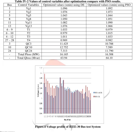
Table IV-2 Values of control variables after optimization compare with PSO results.
Bus Control Variables Optimized values (xmin) using DE Optimized values (xmin) using PSO
1 Vg1 1.096 1.092
2 Vg2 1.076 1.073
5 Vg5 1.043 1.044
8 Vg8 1.050 1.051
11 Vg11 1.082 1.090
13 Vg13 1.076 1.066
6 – 9 T1 1.033 0.979
6 – 10 T2 0.979 1.015
4 – 12 T3 1.011 1.033
27 – 28 T4 0.969 0.982
3 QC3 11.425 10.788
10 QC10 12.752 7.589
24 QC24 7.313 11.790
- Total Ploss (MW) 16.165 16.308
- Total Qloss (Mvar) 63.94 64.10
Figure.4 Voltage profile of IEEE-30 Bus test System
V. CONCLUSION
In this paper, ORPD problem with conflicting objectives such as real power loss minimization, bus voltage profile improvement is considered. The uncertainties in the load drifts are handled effectively in multi-objective problem formulation. And also improve,
1. It can reduce costs and system loss and modify voltage profile.
2. It can increase the transfer capacity and thus increase the MW power Delivery of tie lines.
This also comprehensively applies all kinds of optimal reactive power dispatch methods to solve power system operation problems. Some contents are analyzed and discussed in detail in paper. This paper covers not only traditional methods and implementation in power system reactive power optimization and optimal power flow problems evolutionary programming, and particle swarm optimization.
VI. REFERENCES
Hyperlink Ref.:
1. www.pserc.cornell.edu/matpower
2. http://www1.icsi.berkeley.edu/~storn/code.html 3. http://www.ee.washington.edu/research/pstca Book Ref.:
IJEDR1402136
International Journal of Engineering Development and Research (www.ijedr.org)2140
[2] D.P. Kothari, J.S Dhillon, “power System optimization” Second Edition, PHI Publication , 2011.[3] Journal/conference paper Ref-
[4] Durairaj S., Kannan P.S. and Devaraj D., “ Multi-objective VAR dispatch using particle swarm optimization” , International Journal of Emerging Electric Power Systems, 4 (1), 1–16,2005.
[5] B. Zhao C. X. Guo, and Y. J. Cao, “ A Multi-agent - Based Particle Swarm Optimization Approach for Optimal Reactive Power Dispatch”, IEEE Trans. On Power Systems, vol. 20, no. 2, May 2005, pp. 1070-1078.
[6] Wu, Q.H. and Ma, J.T., “Power system optimal reactive power dispatch using evolutionary programming ”. IEEE Transactions on Power Systems, 10 (3), 1243–1248. 1995.
[7] M. Varadarajan, k s Swarup, “Differential evolution approach for optimal reactive power dispatch” Science Direct, 2007. [8] A.A. Abou El Ela, M.A. Abido, S.R. Spea, “Differential evolution algorithm for optimal reactive power dispatch”,
Electric Power Systems Research, science direct, 2011.
[9] Storn, R. and K. Price, “Differential evolution- a simple and efficient heuristic for global optimization over continuous spaces. Journal of Global Optimization”, 11(3), 341–359,1997
[10] Price, K. V., R. M. Storn, and J. A. Lampinen, “Differential Evolution – A Practical Approach to Global Optimization”.Springer-Verlag, 2005.
[11] S. Ramesha, S. Kannanb and S. Baskarc, “An improved generalized differential evolution algorithm for multi-objective reactive power dispatch” Taylor & Francis, Engineering Optimization, 44:4, 391-405, 2012
[12] R.D. Zimmerman et al. ,“MATPOWER: Steady-State Operations, Planning and Analysis Tools for Power Systems Research and Education,” IEEE Trans. On Power Systems, vol. 26, no. 1, Feb. 2011, pp. 12-19.
[13] B. Zhao et al., “A Multiagent-Based Particle Swarm Optimization Approach for Optimal Reactive Power Dispatch”, IEEE Trans. On Power Systems, vol. 20, no. 2, May 2005, pp. 1070-1078.