University of South Carolina
Scholar Commons
Theses and Dissertations
12-14-2015
Impact of Formulation and Processing Parameters
on Mechanical Properties of Magadiite/Elastomer
Composites
Yating Mao
University of South Carolina - Columbia
Follow this and additional works at:https://scholarcommons.sc.edu/etd
Part of theChemical Engineering Commons
This Open Access Dissertation is brought to you by Scholar Commons. It has been accepted for inclusion in Theses and Dissertations by an authorized
administrator of Scholar Commons. For more information, please [email protected].
Recommended Citation
I
MPACT OFF
ORMULATION ANDP
ROCESSINGP
ARAMETERS ONM
ECHANICALP
ROPERTIES OFM
AGADIITE/E
LASTOMERC
OMPOSITESby
Yating Mao
Bachelor of Science,
Dalian University of Technology, 2011
Submitted in Partial Fulfillment of the Requirements
For the Degree of Doctor of Philosophy in
Chemical Engineering
College of Engineering and Computing
University of South Carolina
2015
Accepted by:
Harry J. Ploehn, Major Professor
James A. Ritter, Committee Member
Xiao-dong Zhou, Committee Member
Hanno zur Loye, Committee Member
John W. Weidner, Committee Member
ii
iii
DEDICATION
iv
ACKNOWLEDGEMENTS
I would like to thank my advisor, Dr. Harry Ploehn, who helped me through my
graduate education. Everything that I learned from him will still guide me after my
graduation.
I want to thank my committee members to help to better my work.
I appreciate all my lab colleagues. Special appreciation goes to Dr. Shigeng li,
who taught me how to use everything in the lab when I was new to graduate school. I
really appreciate his help in research and important career advice. Dr. Xiaoming Chen
helped me in my project and lab work patiently, even after he left USC.
My appreciation also extends to all the research groups in Horizon building. I had
a wonderful time in this building. Dr. Benicewicz gave me very useful guide in the
cooperation project. Dr. Frank Chen offered me the permission to use the equipment in
his lab. Dr. Hongying Zhao is a great friend and colleague. I am also thankful to Warren
for the help and funny conversations.
Many people from other departments in USC helped me in my work. I enjoyed
learning in EM center with Dr. Jibin Zhao. Dr. Chao allowed me to run tensile test in his
v
I want to thank all my friends in department of chemical engineering who helped
me to start the new life in the US in 2011. Thanks for Hang Li who offered me exciting
cooperative opportunities. I am very thankful to my dear friends Qiuli Liu, Dr. Lujing
Zhan, Dr. Lei Zhang, Lei Wang, Chao Wang, I can’t forget the time we spent together.
Thanks to my great roommates Dr. Xuan Zhao, Yang Cao, Shengnan Meng and Liang Li
for spending the beautiful days with me. I miss those days in Pavilion Tower and Granby
Oaks.
To my best friends Gloria Sifan Liu and Oclin Lin Wang, the sweetest
conversations encouraged me in the past four years, especially when I was recovering
from surgery and looking for jobs. Our friendship will be forever. Lai Wei, April Yang,
Shixi Qu, Jennifer Zhang, Ying Zhang, Bo Guan, they always gave me strength and made
me happy.
Finally, I want to thank my parents Yun Mao and Hui Jiang. Without their love
and support, I could never make it. I am very proud of my parents and my family. I miss
my grandparents so much. I really wish they were here for me now, but I know they will
vi
ABSTRACT
This work seeks a better understanding of mechanical reinforcement and energy
dissipation in elastomer composites containing the layered silicate magadiite (MGD,
Na2Si14O29·nH2O). We characterized the elastomer’s accessibility into MGD interlayer
spaces and studied the factors that influence the composite mechanical properties. We
also compare the mechanical reinforcement of MGD with montmorillonite (MMT, a
layered aluminosilicate clay mineral), which is widely used as filler in other kinds of
nanocomposites. The study explores the grafting chemistry, vulcanization, and
reinforcement mechanism in MGD/elastomer composites, which may help us to
formulate the platelet/elastomer composites with superior mechanical properties and
performance in the future.
We continued previous work in our group on the influence of organosilane
pre-functionalization on MGD reinforcement.1 Various organosilane-functionlized MGD
(OS-MGD) were reacted with squalene (SQ), a small molecule model for natural rubber.
For OS-MGD with larger initial interlayer spacing, more SQ entered the interlayer space.
For OS-MGD with smaller initial interlayer spacing, SQ was excluded from intercalation.
By calculating the composition based on TGA and EA results, we studied the MGD
grafting chemistry and quantified the SQ accessibility into the MGD interlayer space.
1 Li, S. Reinforcement and Energy Dissipation in Platelet-Filled Elastomers. Ph.D. Dissertation,
vii
Then, we explored various factors that influence the mechanical reinforcement of
composites consisting of MGD dispersed in styrene-butadiene rubber (SBR), such as the
interlayer spacing, various mixing times, the addition of silane coupling agents, different
sulfur sources, the presence of surfactant, and varying elastomer chemistry. Rationalizing
the relationship between those factors and composite mechanical properties provides a
deeper understanding of the reinforcement mechanism and energy dissipation in
MGD/SBR composites.
Finally, we compare the mechanical reinforcement of MGD and MMT in SBR
composites directly. Based on XRD results, MMT was speculated to be partially
exfoliated after compounding with SBR prepolymer, resulting in greater mechanical
reinforcement and higher crosslink density for MMT/SBR composites compared to
MGD/SBR composites. This work helps us to understand and formulate elastomer
viii
TABLE OF CONTENTS
DEDICATION ... iii
ACKONWLEDGEMENTS ... iv
ABSTRACT ... vi
LIST OF TABLES...x
LIST OF FIGURES………..xiii
CHAPTER 1 Introduction...1
1.1 Project Motivation ...1
1.2 Background ...2
1.3 Layered Silicates in Rubber Composites ...11
1.4 Squalene Research Review ...23
1.5 Overview of This Work ...24
CHAPTER 2 Magadiite Silylated with Sulfur-Functional Organosilanes: Investigation of Structure and Interlayer Accessibility ...26
2.1 Introduction ...26
2.2 Materials and Experimental Methods ...27
2.3 Results and Discussion ...30
ix
2.5 Discussion ...50
CHAPTER 3 Organo-MGD/SBR Composites ...52
3.1 Introduction ...52
3.2 Materials and Experimental Methods ...60
3.3 Results and Discussion ...70
CHAPTER 4 Comparison of MMT/SBR and MGD/SBR Composites ...147
4.1 Introduction ...147
4.2 Materials and Experimental Methods ...148
4.3 Results and Discussion ...153
4.4 Conclusion ...170
REFERENCES ...172
x
LIST OF TABLES
Table 2.1 List of ingredients and composition used for squalene grafting reactions with organosilane-functional magadiite (OS-MGD). ... 29
Table 2.2 Summary of TGA results for CTA-MGD and OS-MGD materials. ... 32
Table 2.3 Summary of EA results and composition for CTA-MGD and OS-MGD materials; the compositions are denoted as (CTA)x(OS)ySi14O29∙nH2O where “OS” stands for organosilane. ... 32
Table 2.4 TGA results summary for OS-MGD/SQ products. ... 42
Table 2.5 Summary of EA results and composition for OS-MGD/SQ materials. The compositions are denoted as (CTA)x(OS)ySy’(SQ)z Si14O29·nH2O, where x, y, y’, and z
are the moles of CTA+, organosilane (“OS”), free sulfur, and squalene, respectively, per MGD unit cell. ... 43
Table 2.6 Interlayer spacings of OS-MGD fillers, OS-MGD/SQ and OS-MGD/SBR composites... 48
Table 3.1 Generic recipe for MGD/SBR composites. ... 62
Table 3.2 Mixing procedure for preparation of silica/rubber, MGD/rubber and
MMT/rubber composites. ... 62
Table 3.3 List of samples prepared to explore influence of varying interlayer spacing .. 63
Table 3.4 List of samples prepared to explore the influence of CTA+ addition. ... 64
Table 3.5 List of samples prepared to explore influence of sulfur source. The amounts of sulfur and SI-69 are highlighted. ... 65
Table 3.6 List of samples prepared to explore the influence of mixing time. ... 65
Table 3.7 List of samples prepared to explore the influence of varying elastomer
chemistry. ... 66
xi
Table 3.9 Crosslink densities, Mc values and dispersion ratings of various OMGD/SBR
and silica/SBR samples. ... 86
Table 3.10 Tensile testing results for OMGD/SBR and silica/SBR composites. ... 90
Table 3.11 Dynamic mechanical properties of silica/SBR and various OMGD/SBR composites measured by DMA. ... 93
Table 3.12 Crosslink density and Mc values for CTA-MGD/SBR and silica/SBR composites... 106
Table 3.13 Tensile testing results for CTA-MGD/SBR and silica/SBR samples. ... 108
Table 3.14 Dynamic mechanical properties of CTA-MGD/SBR-1~4 and silica/SBR composites measured by DMA. ... 110
Table 3.15 Crosslink density, Mc values, and dispersion ratings of CTA-MGD/SBR-1,-2, -5, and -6 samples. ... 116
Table 3.16 Tensile testing results for MGD/SBR-1, -2, -5, and -6 samples. ... 122
Table 3.17 Dynamic mechanical properties of CTA-MGD/SBR-1, -2, -5, and -6 composites measured by DMA. ... 124
Table 3.18 Crosslink density, Mc values and dispersion rating values of SBR and BR composites... 132
Table 3.19 Tensile testing results for various BR and SBR composites. ... 135
Table 3.20 TGA results for silica and organically-modified silica samples. ... 137
Table 3.21 Vulcanization characteristics of silica/SBR and CTA-silica/SBR ... 140
Table 3.22 Crosslink density, Mc values and filler dispersion ratings of silica/SBR and CTA-silica/SB.R ... 140
Table 3.23 Tensile testing results for silica/SBR and CTA-silica/SBR composites... 142
Table 3.24 Dynamic mechanical properties of silica/SBR and CTA-silica/SBR composites measured by DMA. ... 143
Table 4.1 Recipes for CTA-MGD/SBR and CTA-MMT/SBR composites. ... 150
Table 4.2 Mixing procedure for preparation of CTA-MGD/SBR and CTA-MMT/SBR composites... 150
xii
Table 4.4 Tensile testing results for CTA-MGD/SBR, silica/SBR, and CTA-MMT/SBR composites... 164
xiii
LIST OF FIGURES
Figure 2.1 XRD patterns for m-SI-69-MGD and m-SI-69-MGD/SQ. ... 33
Figure 2.2 XRD patterns for MPTES-MGD and MPTES-MGD/SQ. ... 34
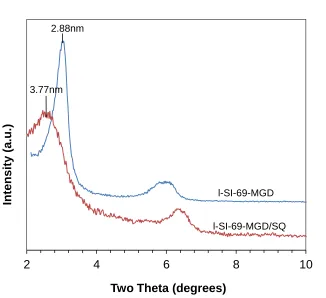
Figure 2.3 XRD patterns for l-SI-69-MGD and l-SI-69-MGD/SQ. ... 35
Figure 2.4 TEM images for (a) m-SI-69-MGD/SQ, (b) MPTES-MGD/SQ, and (c) l-SI-69-MGD/SQ. ... 37
Figure 2.5 IR spectra of SQ, CTA-MGD/SQ, and OS-MGD/SQ. IR spectra with smaller scale are shown for clarity in bottom. ... 38
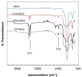
Figure 2.6 IR spectra of SQ, CTA-MGD, and OS-MGD. ... 39
Figure 2.7 TGA weight loss and rate of change (derivative weight) as functions of
temperature for pure squalene. The heating rate was 5 °C/min. ... 40
Figure 2.8 TGA weight loss and rate of change (derivative weight) as functions of
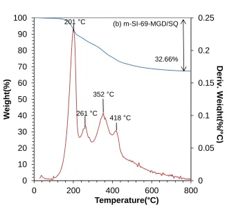
temperature for m-SI-69-MGD/SQ. The heating rate was 5 °C/min. ... 41
Figure 2.9 TGA weight loss and rate of change (derivative weight) as functions of
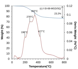
temperature for l-SI-69-MGD/SQ. The heating rate was 5 °C/min. ... 45
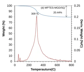
Figure 2.10 TGA weight loss and rate of change (derivative weight) as functions of temperature for MPTES-MGD/SQ. The heating rate was 5 °C/min. ... 46
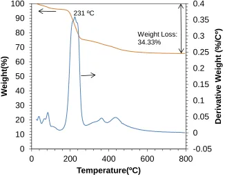
Figure 3.1 TGA weight loss and rate of change (derivative weight) as functions of
temperature for MGD. The heating rate was 5°C/min. ... 71
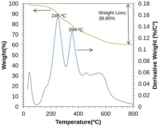
Figure 3.2 TGA weight loss and rate of change (derivative weight) as functions of
temperature for CTA-MGD. The heating rate was 5°C/min. ... 72
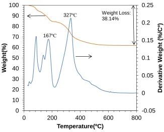
Figure 3.3 TGA weight loss and rate of change (derivative weight) as functions of temperature for DP-MGD. The heating rate was 5°C/min. ... 73
Figure 3.4 TGA loss and rate of change (derivative weight) as functions of temperature for HDA-MGD. The heating rate was 5°C/min. ... 74
xiv
Figure 3.6 XRD patterns for as-prepared Na-MGD and various OMGD materials. All peaks are (001) except as indicated on the plot. Patterns for CTA-MGD and HDA-MGD are shifted upwards for clarity. ... 76
Figure 3.7 XRD patterns for CTA-MGD/SBR-1 composite after batch mixing, milling, and thermal curing (curves labeled “mixed”, “milled”, and “cured”). Composites
prepared with SI-69 added in the batch mixing stage. ... 78
Figure 3.8 XRD patterns for HDA-MGD/SBR composites after batch mixing, milling, and thermal curing (curves labeled “mixed”, “milled”, and “cured”). ... 79
Figure 3.9 XRD patterns for DP-MGD/SBR composites after batch mixing, milling, and thermal curing (curves labeled “mixed”, “milled”, and “cured”). ... 81
Figure 3.10 SEM images of (a) silica/SBR, (b) CTA-MGD/SBR-1, (c) HDA-MGD/SBR, and (d) DP-MGD/SBR composites. ... 84
Figure 3.11 3D topography of CTA-MGD/SBR-1 composite... 85
Figure 3.12 Representative stress-strain curves for various OMGD/SBR and silica/SBR composites... 89
Figure 3.13 Storage modulus as a function of temperature for silica/SBR and various OMGD/SBR composites. ... 93
Figure 3.14 Loss tangent as a function of temperature for silica/SBR and various
OMGD/SBR composites. ... 94
Figure 3.15 XRD patterns for CTA-MGD/SBR-3 composite after batch mixing, milling, and thermal curing (curves labeled “mixed”, “milled”, and “cured”). Composite was prepared with SI-69 added prior to 6 min of batch mixing... 100
Figure 3.16 XRD patterns for CTA-MGD/SBR-2 composite after batch mixing, milling, and thermal curing (curves labeled “mixed”, “milled”, and “cured”). Composite was prepared with no added SI-69 but with 2 min of batch mixing. ... 101
Figure 3.17 XRD patterns for CTA-MGD/SBR-4 composite after batch mixing, milling, and thermal curing (curves labeled “mixed”, “milled”, and “cured”). Composite was prepared with no added SI-69 but with 6 min batch mixing. ... 102
Figure 3.18 SEM images of (1) MGD/SBR-1 (2) MGD/SBR-2 (3) CTA-MGD/SBR-2 (4) CTA-MGD/SBR-4 composites with and without added SI-69 and for varying mixing times as indicated. ... 105
Figure 3.19 Representative stress-strain curves for CTA-MGD/SBR and silica/SBR composites... 108
xv
Figure 3.21 Loss tangent as a function of temperature for silica/SBR and
CTA-MGD/SBR composites... 112
Figure 3.22 SEM images of (1) MGD/SBR-1, (2) MGD/SBR-2, (3) CTA-MGD/SBR-5 and (4) CTA-MGD/SBR-6 composites. The sulfur sources for each
composite are indicated on the image labels... 119
Figure 3.23 Representative stress-strain curves for CTA-MGD/SBR-1, -2, -5, and -6 composites... 121
Figure 3.24 Storage modulus as a function of temperature for CTA-MGD/SBR-1, -2, -5, and -6 composites. Panel (a) shows the full temperature range, and (b) emphasizes the rubbery regime. ... 125
Figure 3.25 Loss tangent as a function of temperature for CTA-MGD/SBR-1, -2, -5, and -6 composites. ... 126
Figure 3.26 XRD patterns for starting CTA-MGD and CTA-MGD in BR and SBR composites... 130
Figure 3.27 Torque profiles for mixing CTA-MGD and silica with SBR and BR. ... 131
Figure 3.28 SEM images of (a) silica/SBR, (b) CTA-MGD/SBR-1, (c) silica/BR, and (d) CTA-MGD/BR composites. ... 132
Figure 3.29 Representative stress-strain curves for SBR and BR composites. ... 134
Figure 3.30 TGA weight loss and rate of change (derivative weight) as functions of temperature for silica and CTA-silica. The heating rate is 5ºC/min. ... 138
Figure 3.31 Cure curves of CTA-silica/SBR and silica/SBR ... 139
Figure 3.32 SEM images of (a) silica/SBR and (b) CTA-silica/SBR composites. ... 141
Figure 3.33 Representative stress-strain curves for CTA-silica/SBR and silica/SBR composites... 142
Figure 3.34 Storage modulus as a function of temperature for silica/SBR and CTA-silica/SBR composites. ... 143
Figure 3.35 Loss tangent as a function of temperature for silica/SBR and
CTA-silica/SBR composites. ... 144
Figure 4.1 Weight loss and rate of change (derivative weight) as functions of
temperature for Na-MMT and CTA-MMT. The heating rate was 5 °C/min. ... 155
Figure 4.2 IR spectra of CTAB, MMT, and CTA-MMT... 156
xvi
Figure 4.4 XRD patterns for CTA-MMT/SBR composites after batch mixing, milling, and thermal curing (curves labeled “mix”, “mill”, and “cure”). The intensity values for cured CTA-MMT/SBR were multiplied by a factor of 30 for clarity... 158
Figure 4.5 XRD patterns for organo-fillers and corresponding SBR composites. Patterns for two SBR composites are shifted upwards for clarity. The curves for CTA-MMT/SBR and CTA-MMT were multiplied by factors of 10 and 0.125, respectively. Panel (a) plots the scale ... 161
Figure 4.6 SEM images of (a) CTA-MMT/SBR and (b) CTA-MGD/SBR composites 162
Figure 4.7 Stress-strain curves for CTA-MGD/SBR, silica/SBR, and CTA-MMT/SBR composites... 165
Figure 4.8 Storage modulus as a function of temperature for CTA-MGD/SBR,
silica/SBR and CTA-MMT/SBR composites. ... 168
1
CHAPTER 1
Introduction
1.1 Project Motivation
In the tire industry, people are familiar with the “magic triangle” for tire
performance: rolling resistance, tread wear and traction. A formulation change that leads
to improvement of one performance metric usually will lead to decreases in other
performance metrics. New additives, like highly dispersible (HD) silica modified with
bifunctional silanes, show promise to stretch this triangle by improving one or more
performance metrics without hurting others.
In our research, we are trying to stretch the magic triangle through the use of
layered silicates with surface chemistry similar to that of HD silica, but with different
particle shape, specifically platelets instead of spheres. Because platelets offer a higher
surface area per unit weight of filler, formulators may be able to use lower weight
loadings to achieve the same mechanical properties as elastomers filled with HD silica.
This would reduce tire weight and save energy. The challenge is to understand the
relationship between formulation and mechanical properties in platelet-filled elastomers,
especially due to the changes and complexities in filler chemistry and microstructure on
various length scales.
This study seeks a better understanding of mechanical reinforcement and energy
2
magadiite platelets (MGD, unit cell formula unit cell formula Na2Si14O29·nH2O. This
research project investigates the silane grafting and vulcanization chemistry of
MGD/SBR composites, the influence of grafting chemistry on MGD interlayer spacing
and particle dispersion, and how these factors influence composite microstructure and
composite mechanical properties.
1.2 Background
1.2.1 Elastomers
Natural rubber (NR) has been obtained from trees for centuries. The elasticity and
water proofing ability of NR initially attracted the attention of scientists. In 1839, Charles
Goodyear and Thomas Hancock discovered that vulcanization improved the strength and
elasticity of rubber and made it less susceptible to temperature changes. NR had low
production volume and high market price due to the limited availability of NR from
natural sources.1
NR was the only available kind of rubber until synthetic rubbers were first
produced in the early 1920s. Synthetic rubber was prepared from monomers derived from
natural gas and petroleum. Since World War II, due to the growth of synthetic rubber
production and the superior properties of synthetic rubber, the market share of NR
dropped from 100% in 1940 to 30% in 1978. Since then, the market share rebounded and
now remains at 40% due to the large need for NR in radial tire construction. Compared to
NR, synthetic rubber has better resistance to light, heat, and organic fluids. It is also
possible to modify the chemistry and structure of synthetic rubber so that the properties
3
Based on properties and structure, synthetic rubbers are divided into several types:
diene rubber, saturated rubber, solvent resistant rubber, temperature resistant rubber,
specialty rubber, thermoplastic rubber, etc.1 The applications of some common rubber
types will be introduced next.
(1) Diene Rubber
Styrene butadiene rubber (SBR), butadiene rubber (BR) and isoprene rubber (IR)
are common diene rubbers. In this group, SBR is produced in the greatest volume. It is
used to manufacture tires and tire products due to its excellent abrasion resistance and
better cost/performance/processing balance. BR is widely used in the tire treads. IR-based
NR polymers are widely used in the treads of heavy duty truck and bus tires because of
their good wear resistance and low hysteresis under heavy load conditions.
(2) Saturated Rubber
Saturated rubbers include propylene copolymers (EPM),
ethylene-propylene-diene terpolymers (EPDM), butyl and halobutyl rubbers (IIR and BIIR/CIIR),
and ethylene-acrylic elastomers (EAM). Saturated elastomers possess better
environmental aging resistance than diene elastomers. The main applications of EPM and
EPDM are in manufacturing of hoses and seals. IIR and BIIR/CIIR are commonly used in
inner tubes due to their low air permeability, as well as in some other tire products. EAM
is used in automotive applications.
4
Nitrile rubber (NBR) is a widely used solvent resistant elastomer. Its principal
uses are in seals, O-rings, and gaskets due to its great chemical resistance.1
1.2.2 Elastomer Composites
Pure, crosslinked rubber has poor physical properties, so filler materials are added
to prepare elastomer composites with improved properties. In fact, elastomer
nanocomposites have existed for decades, considering that carbon black and silica
particles added to elastomers have an average size ranging from 5 to 100 nm.2 The
concept of the nanofiller was introduced to the rubber industry in 1993.3 The term
“nanocomposite” was first introduced one year later4
: it represents a kind of material with
nanofillers dispersed into a matrix material.5,6,7 A nanofiller is a particulate material
having at least one nanoscale dimension (~100 nm) and thus a large specific surface area
(surface area per unit mass of filler). When dispersed uniformly in polymer matrix, the
nanofiller may have large interfacial surface in contact with polymer, which could have a
decisive effect on nanocomposite properties and performance.8
Compared to conventional composites, nanocomposites may be able to achieve
comparable (or better) mechanical properties using much lower amounts of filler,
reducing weight and improving strength/weight ratio. Also, nanofillers are used to
achieve enhanced properties of rubber products, such as tensile strength, hardness,
abrasion resistance, flame retardance, electrical conductivity, and permeability.
Nanocomposites have attracted considerable academic and industrial attention due to the
5
Carbon black (CB) has been used as a rubber-reinforcing agent since 1904. Most
CB is used in the tire industry, because the CB improves the strength and abrasion
resistance of automotive tires. Many other rubber products incorporate CB, including
conveyer belts and consumer products such as footwear and shock absorbers.1 However,
the application of CB is limited by its dark color, tendency to cause environmental
pollution, and shortcomings including poor aging resistance and fatigue.9
Going beyond CB, silica is another important reinforcing filler widely used in the
rubber industry. After the introduction of silica in passenger tires in the 1990s, the use of
silica in the rubber industry developed rapidly. Compared to CB, silica provides higher
wet traction and better rolling resistance without much loss of wear resistance. However,
the application of silica is restricted by higher process cost and performance issues
caused by filler agglomerations in rubber composites.8,9
1.2.3 Coupling Agents
The advent of coupling agents improved the performance of silica in rubber
composites.1 Coupling agents are generally bi-functional molecules that establish
molecular bridges at the interface between the polymer matrix and the filler surface.
Through these interfacial bonds, coupling agents are able to enhance the degree of
polymer-filler interaction by reducing surface energy of the fillers.10
Among all coupling agents, bis(3-triethoxysilylpropyl)tetrasulfane, known as
SI-69 (Scheme 1.1), is often used for tire tread formulation.11 Utilization of SI-69 in
silica-filled rubber compounds improves modulus, compression set, heat build-up, and abrasion
6
in the reaction between silica and SI-69.10 The ethoxy groups of SI-69 react with silanol
groups on the silica surface to produce grafted silane. The tetrasulfane group SI-69 opens
up under curing conditions. The two sulfur atoms attached to the silanes react with
unsaturated (-C=C-) alkene sites in the rubber to produce elastomer-silica crosslinks. The
tetrasulfane also releases two sulfur atoms that produce additional crosslinking.12 The
application of SI-69 is the key factor for the success of silica for partial replacement of
CB as an active filler in the tread compound of the “green tire”.13
Scheme 1.1 Structure of triethoxysilylpropyltetrasulfide (SI-69).
SI-69 is widely used to promote adhesion between inorganic fillers and polymer
matrices. Many articles reported that SI-69 improved dispersion of various fillers,
resulting in better mechanical properties. Tian et al.14 found, using Scanning Electron
Microscope (SEM) images, X-ray diffraction (XRD), and Payne effect results, that SI-69
improved the dispersion and enhanced interfacial adhesion of fibrillar silicate clay in
SBR composites, which resulted in better hardness, tensile modulus and the tear strength.
Alkadasi et al.15 found after treatment with SI-69, China clay showed better filler
dispersion in SBR and improved mechanical properties, such as tensile strength, tensile
modulus, Young’s modulus, and hardness. In Wang et al.’s work16, SI-69 modified
7
showed higher modulus and elongation at break values. Ismail et al.17 studied the
influence of SI-69 on mechanical properties of recycled poly(vinyl
chloride)/acrylonitrile-butadiene rubber/fly ash (PVCr/NBR/FA) composites. The
addition of SI-69 increased the interfacial interaction between fillers and polymer matrix,
and also improved the filler dispersion. The resulting tensile strength, tensile modulus,
and elongation at break also improved. Sun et al.18 concluded that SI-69 improved the
dispersion of silica in SBR composites and the increased silica-SBR bond strength,
leading to enhanced tensile properties of the vulcanized rubber. In conclusion, SI-69
improves filler dispersion as it makes the silicate particles less hydrophilic, which lowers
the dispersion energy. Thus the particle dispersion is promoted, resulting in improved
mechanical properties.
The effect of SI-69 on mechanical properties is influenced by other compositional
and processing parameters during reaction. Ward et al.19 found that the complex shear
modulus and stress-strain results were not changed much by the addition of SI-69 in
S-SBR with silica loading lower than 70 phr. They thought that S-S-SBR interacted with
silica by itself, and the addition of SI-69 did not improve the interaction very much. In
another study on organically modified MMT (OMMT)/NR composites20, the addition of
SI-69 didn’t influence the tensile properties of OMMT/NR composites. They speculated
that the mixing temperature of 50ºC was too low, which led to ineffective chemical
reaction between SI-69 and OMMT. Other factors are sometimes critical in fully
realizing the advantage of SI-69.
Some studies have noted that there is an optimum SI-69 amount in rubber
8
reinforcement. Yamsaengsung et al.21 claimed that in wood sawdust/ NR composites, the
crosslink density increased with SI-69 content increasing from 0 to 0.5 wt%, and then
decreased with greater amounts of SI-69. Similar results were reported in silica/SBR
composites18, fly ash/NR composites 22and silica/NR/SBR blends23. They attributed this
phenomenon to either the steric hindrance effect from tri-ethoxylsilypropyl groups, or the
formation of mono- and poly-layers from self-condensation of the SI-69. The addition of
an optimum amount of SI-69 improves the crosslink density and mechanical properties
effectively. Excessive SI-69 levels may diminish mechanical reinforcement.
The addition of SI-69 in elastomers also influences the scorch time (the time
delay before curing begins) and the cure time (the time to achieve 90% of complete
crosslinking). Increases in scorch time and cure time with increasing SI-69 amounts were
reported in grass fiber/NR composites24, NR/SBR blends filled with silica from fly-ash25,
and NR composite containing short cellulose fiber/silica hybrid filler26. However, the
addition of SI-69 decreased the cure time in SBR/NBR blends filled with CB/silica.27
Thus, the influence of SI-69 on scorch time and curing time depends on the chemistry of
the filler/elastomer system.
Some studies compare the performance of SI-69 with other coupling agents. Sun
et al.18 observed that silica/SBR composites with SI-69 had better performance for some
properties, such as tensile strength, modulus, shore hardness and resilience rate, when
compared with other coupling agents, including: γ-amino propyl- triethoxysilane
(KH550), γ –glycidoxypropyltrimethoxysilane (KH560),
3-(trimethoxysilyl)-1-propan-amine (KH540), 3-(methacryloxy) propyl-trimethoxysilane (KH570), and
9
preparing silica/SBR composites containing various silanes. They used two bifunctional
silanes: SI-69 and 2,5-(triethoxysilylpropylthia)-1,3,4-thiadiazole (S4), and four
monofunctional ones: 3-octanoylthio-1-propyltriethoxysilane (NXT),
1-[3-(octanoylthio)propyl]-1,1,3,3,3-pentaethoxy-1,3-disilapropane (S1),
bis[3-(octanoylthio)-1-propyl]-diethoxysilane (S2),
5-(triethoxysilylpropylthia)-2-potassium-1,3,4-thiadiazolate (S3). It was concluded that the bifunctional silanes produced more
crosslinking than the monofunctional ones. Each bifunctional silane molecule connected
two different silica particles with two separate polymer chains. Silanes containing
nitrogen atoms (e.g. S3 and S4) led to shorter cure time. SI-69 promoted the tensile
properties and abrasion resistance the best, but it was not as good as NXT, S1 and S2 at
improving the rolling resistance and wet traction of tire materials. Thus, the choice of
silane depends on the final application of the material.
1.2.4 Other Nanofillers
In addition to CB and silica, other novel nanofillers have been extensively studied:
nanoclay, carbon nanotubes, graphenes, nanocellulose and ceramics.2,28,29,30,31,32,33,34,35
The resulting rubber nanocomposites showed excellent mechanical properties, thermal
stability and electrical conductivity.2,36 Rubber composites based on nanoclays, known
better as layered silicates, are reviewed in the next section.
1.2.5 Rubber Vulcanization
Rubber vulcanization is the process by which chemical and physical crosslinks
are formed between individual polymer chains. It is an irreversible process. Vulcanized
rubber shows superior mechanical properties compared to uncured, green rubber. The
10
The curing process is commonly characterized using an oscillating disk rheometer.
The principle is to monitor the torque required to maintain given amplitude of oscillation
at a specific temperature. It is assumed that the measured torque during vulcanization
increases in proportion to the degree of crosslinking. The curing curve, a plot of torque
versus time, provides information on polymer crosslink formation during vulcanization,
and is extensively used to monitor the quality of rubber materials.37
Usually, each curing curve consists of three regions: scorch delay, curing, and
overcure. Scorch delay is an initial period in which the cure rate is very low. Most of the
accelerators react during the scorch delay period. Short scorch delay may cause
processing problems. The formation of three dimension network occurs during curing
period, indicated by a sudden increase of cure rate. At the end of curing reaction, a
plateau in torque is observed in the third region, known as overcure, indicating the
maturity of the network. Different polymers show different overcure trends, such as
increase, equilibrium or reversion.2
Sulfur vulcanization has been utilized primarily in the rubber industry for over 70
years. Sulfur vulcanization reactions could only proceed quickly due to the presence of
accelerators and activators. Without these, the reaction is not efficient and takes a long
time. The addition of activators and accelerators optimizes the vulcanization process,
such as shortening the cure optimum time, lowering reaction temperatures, and
improving thermal and oxidative antidegradation.2,37
Accelerators speed the crosslinking reaction and reduce the required sulfur
amount, thus avoiding “bloom” and improving compound aging. There are many types of
11
2-benzothiazyl sulfonamides are the most common accelerators used in rubber industry.
During vulcanization, sulfonamides produce crosslinking and also provide scorch delay
time for processing. Usually, accelerators are used in combination.37
The accelerators must be activated by activators. The most commonly used
activators are zinc oxide and stearic acid. The stearic acid reacts with the zinc oxide and
solubilizes the zinc ion to react with accelerators.38 The mechanism of sulfur
vulcanization involves Zn+ ions (from reaction between steric acid and zinc oxide) first
forming complexes with accelerators. The resulting complex with sulfur and activators
produces the active sulphureting agent that creates rubber polysulfides. The rubber
polysulfides react and form crosslinks (C-Sx-C). However,the mechanism of rubber
vulcanization is still in dispute concerning whether the main reaction occurs via ionic or
free-radical mechanism.2,39,40
In this work, n-cyclohexylbenz-thiazylsulfenamide (CBS) accelerator is used as
the primary accelerator. Diphenylguanidine (DPG) is used as an activator for
sulphenamides and as secondary accelerator in tire tread compounds. It is widely used in
silica/rubber to achieve low rolling resistance.38,39 The stearic acid and zinc oxide are also
activators.
1.3 Layered Silicates in Rubber Composites
Nanocomposites filled with layered silicates have been well known since the
famous work on Nylon 6 by Toyota.3,41 Clay minerals are obtained from natural sources,
can be purified and sold in large quantities of relatively low cost, and are not regarded as
12
been found to improve mechanical properties (such as tensile strength, tear strength,
abrasion resistance), increase solvent resistance or biodegradability, and decrease
permeability and flammability.2
1.3.1 Montmorillonite
Montmorillonite (MMT) plays a major role among the nanofillers. It is an
abundantly available natural resource with low price and important properties, like high
aspect ratio (length/thickness), the unique intercalation/exfoliation characteristics, and a
safe toxicological profile.42
MMT has a 2:1 layered structure consisting of an octahedral sheet (O) of alumina
sandwiched between two silica tetrahedral sheets (T), with the T and O sheets covalently
linked by the apical tetrahedral oxygens.35,43 Three sheets (TOT) form one clay layer.
These layers, called platelets, are stacked to form MMT particles. Due to isomorphous
substitution of Fe2+ for Al3+ in the octahedral sheets, each MMT layer has a net negative
charge that is balanced by cations in the interlayer space. The interlayer cations are
hydrated and loosely bound; they may be exchanged with other cations, so that MMT has
a relatively large cation exchange capacity.43
In each layer, strong iono-covalent interactions exist to keep the layer in one piece.
The layers are held together by relatively weak forces in the direction perpendicular to
the layers, so that upon dispersion into water, MMT layers are easily separated, or
exfoliated, into individual platelets.
The aspect ratio is defined as the average ratio of platelet length to thickness. The
13
aspect ratio and platelet-matrix interaction.44 Our group’s previous work45 used atomic
force microscopy (AFM) to quantify the distribution of MMT platelet aspect ratio, lateral
dimensions, and the degree of exfoliation in water. The aspect ratio of MMT platelets
closely follows a log-normal distribution. Exfoliated MMT platelets usually have aspect
ratios in the range between 50 to 2000.44
Due to the presence of hydrated interlayer cations, MMT platelets are hydrophilic
and have poor interaction and adhesion with organic polymers. The majority of past
studies show that when no compatibilizing ingredients are added, pristine MMT shows
little or no change in interlayer distance, indicating that polymer does not enter the
interlayer spaces.2 In order to improve compatibility with rubber, MMT may be modified
by organophilic surfactants, such as primary alkyl amines and various alkyl ammonium
cations. The resulting organo-modified MMT (OMMT) has better dispersion in rubber
matrices, resulting in improved mechanical properties.8,46
1.3.2 MMT/rubber composites
As nanofillers in rubber, clay minerals have excellent features: high aspect ratio
and nano scale thickness. However, platelets tend to stack and form agglomerates in
rubber.2 Only when fillers are intercalated or exfoliated by polymer, the resulting
composites are classified as nanocomposites.9 Intercalated nanocomposites occur when
polymer intercalates into the interlayers. This may be caused by the penetration of
polymer chains or the structural reorganization of organic modifier. Exfoliated
nanocomposites occur when individual clay layers are isolated and separated randomly.
This may be caused by intercalation of polymer chain into interlayers sufficient to fully
14
thought to be achieved in exfoliated nanocomposites in which platelets have greatest
interaction with rubber matrix through large interfacial surface area, resulting in superior
reinforcement.2,9
MMT has been used as a filler in various rubber composites, including NR, SBR,
BR and EPDM. Past studies of each kind of rubber composite will be reviewed below.
(1) Styrene Butadiene Rubber
There have been many reports about OMMT/SBR nanocomposites in which
intercalated or partially exfoliated MMT improves mechanical properties.47,48,49,50,51,52
Mousa et al.49 reported that the incorporation of up to 10 phr OMMT improved the
tensile stress and modulus at 300% elongation. MMT platelets with high aspect ratio
were most effective in reinforcing the material. Zhang et al.50 found that the tensile
properties and hardness of OMMT/SBR were comparable to CB/SBR when OMMT filler
loading was less than 40 phr. However, there are not many studies that compare
OMMT/rubber with CB/rubber composites using formulations that are realistic for tire
rubber mixes.
(2) Natural Rubber
Natural rubber (NR) is also commonly used as the matrix for
nanocomposites.53,54,55,56,57,58,59 OMMT has shown outstanding performance in
reinforcing NR composites. Varghese et al.58 prepared OMMT/NR nanocomposites with
10 phr OMMT. The nanofillers were partially exfoliated in rubber composites based on
phr denotes “per hundred rubber” by weight. Thus 10 phr OMMT in SBR represents a mixture of
15
XRD results and TEM images. Compared to pristine MMT, OMMT/NR showed shorter
curing time and enhanced tensile properties. In a work on OMMT/NR composites by
Arroyo et al.60, both tensile strength and elongation at break of NR composites with 10
phr OMMT were superior to the composite with 40 phr CB. Some groups have reported
that OMMT pre-intercalated by fatty acid or prepolymer will result in enhanced
mechanical properties. Rooj et al.55 pre-intercalated OMMT with fatty acid with 22
carbon atoms (docosanoic acid). Then, NR nanocomposites were prepared with 4 phr
pre-intercalated OMMT. MMT showed an pre-intercalated structure with interlayer spacing of
5.4 nm in NR composites. Compared with unfilled NR, tensile strength and modulus at
300% elongation improved 114% and 203% respectively. Similar results were obtained
in Das et al’s work.61 In Boonchoo et al.’s work54, polyisoprene–montmorillonite (PIP–
MMT) nanocomposites were synthesized via microemulsion polymerization. The
pre-intercalated PIP increased the interlayer distance of MMT from 3.1 nm to 3.8 nm. NR
with PIP-MMT showed improved tensile strength and elongation at break compared to
unfilled NR.
(3) Nitrile Rubber
Many studies reported nanocomposites with nitrile rubber (NBR) as the matrix
and OMMT as fillers.62,63,64,65,66 Sousa et al.64 found that the incorporation of OMMT in
NBR nanocomposites improved tensile properties compared to unfilled NBR. XRD
showed intercalated structure of MMT in NBR. Alhmadi et al.’s work66 showed OMMT
was exfoliated in NBR nanocomposites. Especially when nanofiller contents were more
than 5 phr, both modulus and ultimate strength were much larger in OMMT/NBR than
16
gamma radiation of nanocomposites improved the thermal stability and filler dispersion
more than OMMT/SBR.
(4) Ethylene Propylene Diene Terpolymer
Another extremely durable polymer, ethylene propylene diene terpolymer
(EPDM), has also been used to prepare rubber nanocomposites.67,68,69 Zheng et al.67
treated MMT with methylbis(2-hydroxyethyl)cocoalkylamine, and then prepared EPDM
nanocomposites containing 15 phr pretreated OMMT. Fillers showed exfoliated structure
in nanocomposites, which was verified by XRD patterns. The resulting exfoliated
nanocomposites show great improvement in modulus and hardness. Ahmadi et al.68
compared the mechanical reinforcement of OMMT and MMT in EPDM composites.
When OMMT loading was from 2 to 10 phr, an exfoliated structure was obtained based
on XRD results and TEM images. OMMT/EPDM nanocomposites show superior tensile
properties, hardness and solvent resistance compared to MMT/EPDM composites.
1.3.3 Magadiite
Magadiite (MGD) belongs to a group of aluminum-free layered silicate hydrates43
that has attractive properties, including resistance to acids, good ion exchange properties,
and ability to intercalate organic cations. Other minerals belonging to this group include
kanemite, octosilicate, kenyaite, and makatite. Hydrothermal synthesis conditions and the
ratio between the sodium and siliceous components play decisive roles in the formation
of two-dimensional structure in layered silicates.43
The general formula for layered silicate hydrates is (Na∙2H2O)aHa∙ [a(Si2O5)
17
composed of [SiO4] and [SiO3OH] units. Arrangements of the [SiO4] tetrahedral of some
layered silicates are shown in Scheme 1.2. The interlayer space contains cations to
neutralize the layer negative charge.
Scheme 1.2 Arrangements of the [SiO4] tetrahedra as structural building units of silicatic
layered materials. Reproduced with permission from Handbook of Layered Materials.43
The SiO2/Na2O ratio is used to classify layered silicates into different groups.
The basal spacing d and the interlayer distance Δd are characteristic features for the
layered silicates.43 Some research shows with the increase of the SiO2/Na2O ratio, the
basal spacing d decreases.
Of all the layered silicate hydrates, the crystal structures of kanemite and makatite
are the only ones to have been confirmed. Because no single crystal of magadiite has
been found, its crystal structure is not determined yet. According to many TGA and NMR
18
improvements in analytical technology will help us to better understand the sodium
silicate hydrate group, so far the structural relationship among group members has not
been figured out.43
In MGD, interlayer sodium cations compensate the negative charged layers. The
compensating cations are loosely bound and easily exchanged by inorganic and organic
cations.70 Iler published a study of layered silicates cation-exchanged with metal cations,
including Li+, Na+, Mg2+ and hexadecyltrimethylammonium cations in early 1960s.71
Other metal cations such as Zn2+, Eu3+ and Co2+ have been exchanged and absorbed into
MGD.72,73,74 Due to its cation exchange ability, MGD has been explored for use as
molecular sieve, cation exchanger, adsorbent and catalyst support. The lack of covalent
bond formed during cation-exchange reaction makes intercalated cations easily released
or exchanged.75
Incorporation of organic cations has been studied due to the potential application
of organo-modified modified MGD (OMGD) in polymer composites. OMGD has larger
interlayer spacing, making it much easier to be intercalated further by other organic
molecules. Lagaly et al.76explored MGD cation exchange and reported the interlayer
sodium cations were exchanged by alkylammonium-, dimethyldialkylammonium-,
trimethylalkylammonium, and alkylpyridinium cations. They also reported the surface
area of the MGD unit cell (Si14O29) to be 0.55 nm2. Kooli et al.77 quantified the maximum
amount of cetyltrimethylammonium cations (CTA+) exchanged per unit mass of MGD as
1.16 mmol /g. Wang et al.78,79 treated MGD with various octadecylammonium
19
ranging from C12 to C18, in order to explore the influence of various ammonium cations
on MGD interlayer distance and layered structure.
It is possible to control interlayer distance and grafting density by covalent
modification of the MGD interlayer surface. Mostly MGD intercalated by
alkylammonium cations have been used as intermediates. Layered silicates can be
modified covalently by various silanes, known as silylation. Okutomo et al.80 used the
dodecyltrimethylammonium-exchanged MGD as the intermediate and studied silylation
of MGD by trimethylchrolosilane, triethylchlorosilane, triisopropylchlorosilane,
butyldimethylchlorosilane, octyldimethylchlorosilane, and octadecyldimethylchlorosilane.
Isoda et al.81 successfully reacted γ-methacryloxypropyltrimethoxysilane with
dodecyltrimethylammonium-exchanged MGD. Fujita et al.82 used various amounts of
octyltrichlorosilane to react with dodecyltrimethylammonium-exchanged magadiite.
They found for samples reacted with lower amounts of silane, the resulting MGD
absorbed more alcohol guest molecules and showed larger final interlayer distance. The
covalent modifications make it possible for MGD to immobilize various functional
groups. The resulting silane functionlized MGD may have a wide variety of applications,
such as selective adsorbents, nanoparticle supports, and active fillers for
nanocomposites.70
1.3.4 Magadiite/Polymer Composites
Magadiite has not been used as widely as MMT as the inorganic filler in polymer
composites. Several reports describe the use of MGD in epoxy, polystyrene, and SBR
composites in order to compare the reinforcement performance directly with composites
20
cetyltrimethylammonium cations (CTA+) the resulting CTA-MGD was intercalated with
3-(2-aminoethylamino) propyltrimethoxysilane (AAPTS) or
aminopropylmethyldiethydiethoxysilane (APMDS). The AAPTS-MGD and
APMDS-MGD had interlayer distances of 2.419 nm and 1.862 nm, respectively. AAPTS-APMDS-MGD
was mixed with SBR prepolymer in toluene suspension, with the mass ratio of modified
MGD to SBR at 1:20. AAPTS-MGD/SBR had exfoliated structure based on XRD results.
AAPTS-MGD/SBR and APMDS-MGD/SBR had a 3.4% and 3.1% reduction,
respectively, in gas permeability compared to the control SBR. However, mechanical
properties of composites were not reported. A considerable amount of toluene was
needed to achieve MGD exfoliation via this preparation method, which is not practical in
industry.
Wang et al.84 treated MGD with styryldimethylhexadecylammonium cations, and
the resulting organo-MGD (OMGD) was used to prepare polystyrene nanocomposites via
bulk polymerization. The mass ratio of OMGD to monomeric styrene was 3:100. They
also prepared OMMT/PS composites using the same procedure.85,86 OMGD/PS
composites showed better Young’s modulus than OMMT/PS composites. They
speculated the larger MGD platelets might provide stronger filler-polymer interaction.
Wang et al.78 modified MGD with a mix of octadecylammonium cations and
octadecylamine. By adjusting the ratio of octadecylammonium cations to octadecylamine,
three OMGD structures were obtained: monolayer, lipid, and paraffin structure. These
three OMGD materials were reacted with epoxide resins to form OMGD/epoxy
composites with 15 wt% OMGD content. The paraffin-like OMGD was the only one to
21
pristine MGD and lipid-like OMGD composites. Wang and Pinnavaia79 also prepared
epoxy nanocomposites with various octadecylammonium Ch3(CH2)17NH3-n(CH3)n+
(n=1,2,3) exchanged MGD, denoted as C18A1M-, C18A2M-, and C18A3M-MGD.
Composite tensile strength was higher in exfoliated epoxy nanocomposites obtained from
C18A1M-MGD and C18A2M-MGD compared to the intercalated structure formed by
C18A1M-MGD. At the same time, they also prepared composites of C18A-MMT and
epoxy using the same procedure in order to compare with the reinforcement of
C18A-MGD directly. When filler loading (wt% SiO2) was below 5 wt%, C18A-MGD and
C18A-MMT showed comparable properties. When filler loading (wt% SiO2) was higher
than 5 wt%, C18A-MMT showed better reinforcement as measured by tensile strength
and modulus.
Some previous work aimed at preparing MGD/polymer composites for flame
retardancy applications.87 Wang et al.84 prepared polystyrene (PS) composites with MGD
exchanged with styryldimethylhexadecylammonium cations via bulk polymerization.
SEM images of MGD/PS composites clearly showed tactoids, indicating poor interaction
between filler and matrix. The addition of OMGD did not change the thermal degradation
onset and the pathway, which means that organo-MGD was not a fire retardant for PS.
Morgan et al.88 treated MGD with various inorganic and organic cations and prepared
MGD/polyethylene-co-vinyl acetate (EVA) composites. Compared to organo-MGD,
pristine MGD showed the better flammability performance in EVA. It was speculated
that MGD formed silicate glass to reduce the mass transfer during flaming.
Previous research on MGD/SBR was carried on by Dr. Shigeng Li in his
22
investigate MGD as an alternative filler material to silica. MGD has similar surface
chemistry to silica, but different filler particle shapes and sizes. Comparing MGD and
silica as fillers in SBR was carried out to explore reinforcement mechanisms and energy
dissipation in platelet-filled elastomers. In Dr. Li’s work, he generally made three types
of MGD/SBR composite materials: (1) unmodified MGD in SBR, (2) CTAB pretreated
MGD in SBR and (3) SI-69 pre-functionalized CTA-MGD in SBR. For samples with
unmodified MGD, the MGD did not disperse well during batch mixing with SBR
pre-polymer. Consequently the mechanical properties of cured MGD/SBR composites were
poor compared to silica/SBR.
The most interesting material was prepared by blending CTA-MGD with SI-69
and SBR pre-polymer in the batch mixer. The incorporation of CTA+ expanded the
interlayer space of MGD interlayers. The interlayer surface area was believed to be more
accessible to SBR pre-polymer in batch mixing, resulting more intimate interaction
between the SBR matrix and MGD. CTA-MGD/SBR has improved mechanical
properties compared to those of silica/SBR composites based on DMA and tensile test
results.
In addition to exploring CTA-MGD/SBR, Li also investigated pre-grafting SI-69
onto MGD and preparing composites using those sulfur-modified fillers. In this work, he
found that the added SI-69 would graft onto the MGD interlayer surface, replacing bulky
CTA+. When the graft density of SI-69 on MGD surfaces was high, SBR prepolymer
would not enter into the MGD interlayer space. The resulting composites did not have
improved mechanical properties. However, when lower amounts of SI-69 were grafted
23
spacing remained almost the same as that of CTA-MGD. The composites prepared from
the MGD with low SI-69 grafted amounts had the best mechanical properties, superior to
those of silica/SBR. However, these composites were prepared without added sulfur as
the curing agent, so they did not have mechanical properties as good as those of
CTA-MGD/SBR prepared with both added SI-69 and sulfur.
1.4 Squalene Research Review
The previous research of Li75 showed that MGD with pre-grafted
sulfur-functional silanes might be useful. The ability of SBR prepolymer to enter the MGD
interlayer space depends on the silane grafting density and possibly other factors.
Unfortunately, testing the usefulness of silane-functionalized MGD required the
preparation of elastomer composites and characterization of composite structure and
properties, which is a long, labor-intensive process. In the present work, Li’s
sulfur-functionalized MGD materials were reacted with squalene, a model compound for NR, to
test the accessibility of MGD interlayers. This work is described in Chapter 2.
Squalene (SQ) is a natural 30-carbon organic compound with six double bonds. It
was originally obtained from shark liver oil. Today, plant materials are now used as a
source of squalene, including amaranth seed, rice bran, wheat germ, and olives.89 The
24
Scheme 1.3 Structures of (a) squalene and (b) natural rubber.
Due to its structural similarity to NR, squalene has been used as a model
compound for NR in much research. Bloomfield et al. used SQ in the first published
studies of the reactions of sulfur and sulfur compounds with olefinic substances at the end
of the 1940s.90,91 Since then, SQ has been used extensively in the context of the Model
Compound Vulcanization (MCV) approach for investigating vulcanization reactions.92,93
Boretti et al. proved that, compared to simpler model compounds, SQ is a more realistic
model compound for polyisoprene in accelerated sulfur vulcanization, because of the
adjacent methylenic carbons.94 Many groups have used SQ/MCV to study various aspects
of vulcanization mechanisms, including heating source,95 filler surface structure,96
sulfonamide accelerators,93 zinc oxide, 39,97 and other inorganic activators,98 and mixed
metal oxide nanoparticles.99
1.5 Overview of This Work
The overall objective of this work is to study the nanoscale and macro-scale
structure of elastomer composites containing layered silicate fillers. It seeks a deeper
understanding of the reinforcement mechanisms of layered silicates, mainly MGD,
expanded with organic cations and then used in place of silica in realistic tire rubber
25
As mentioned in section 1.4, Chapter 2 reports on our investigation squalene (SQ),
a model compound for NR, which is introduced to explore the ability of elastomer to
intercalate into the MGD interlayer space and react with pre-grafted SI-69. This work
completes the study of sulfur-functionalized MGD initiated by Li.75
Based on Li’s dissertation research,75
CTA-MGD appears to be a promising active
filler for SBR. Building upon Li’s work, in Chapter 3 we explore various factors that
influence the reinforcement mechanism in organo-MGD/elastomer composites. The
factors include interlayer expansion by different organic cations, variations in composite
formulation (recipe), and variations in processing conditions. MGD structure and the
mechanical properties of elastomer composites are characterized, in order to rationalize
the relationship between various factors and the reinforcement of elastomer composites
by MGD.
In Chapter 4, we compare the SBR mechanical reinforcement by MGD with
another widely used layered silicate, montmorillonite (MMT). MGD and MMT are
blended into SBR to prepare elastomer composites using the same procedure and recipe.
The work aims at comparing the reinforcement of two different layered silicates in rubber
26
2
CHAPTER 2
Magadiite Silylated with Sulfur-Functional Organosilanes: Investigation of
Structure and Interlayer Accessibility
2.1 Introduction
In Li’s previous work75
, organosilane-MGD (OS-MGD) was prepared to explore
the influence of silane pre-functionalization on MGD reinforcement. OS-MGD was
prepared by reacting CTA-MGD with varying amounts of silane. The OS-MGD showed
varying interlayer spacings and silane grafting densities. When a larger amount of silane
was used, most of the CTA+ in CTA-MGD was replaced by silane, resulting in a smaller
interlayer spacing and poor mechanical reinforcement in SBR composites. When a lower
amount of silane was used, some CTA+ remained in the interlayers and maintained a
large interlayer spacing. The best mechanical properties were observed in SBR filled with
OS-MGD with lower silane graft density.
The preparation of rubber composites is complicated, labor- and time-consuming.
The cured rubber composites are not soluble in many solvents, which limits the use of characterization methods to study the surface chemistry of the filler. In this chapter, we introduce a small chemical compound, squalene (SQ), to react with OS-MGD in order to
study the chemistry of MGD in SBR composites. Much research on rubber vulcanization
mechanisms has been carried out using SQ due to its structural similarity (Scheme 1.3) to
27
accessibility of the OS-MGD interlayer to elastomer chains by characterizing the amount
of grafting SQ. We also explore the relationship between the initial starting interlayer
spacing and the amount of grafting SQ per sulfur site (S-site). To evaluate SQ grafting as
a screening test for active fillers in rubber composite formulation, we compare the
interlayer spacing of OS-MGD/SBR composites directly with the corresponding layer
spacing in MGD/SQ. The preparation and characterization of MGD and
OS-MGD/SBR were mostly reported by Li in his dissertation research.75 In this chapter, we
focus on the preparation and characterization of OS-MGD/SQ.
2.2 Materials and Experimental Methods
2.2.1 Material Preparation
2.2.1.1 Modification of Magadiite
Sodium magadiite (Na-MGD) was synthesized using the hydrothermal method83
and treated with cetyltrimethylammonium bromide (CTAB, Sigma-Aldrich, used as
received), resulting in cation exchange of CTA+ for interlayer protons to produce
CTA-MGD.75
2.2.1.2 Silylation of CTA-magadiite
Varying amounts of bis-triethoxysilylpropyltetrasulfide (TESPT, also known as
SI-69, provided by Michelin Americas Research) were mixed with dried toluene. Then
MGD was added to the SI-69/toluene solution, resulting in various silylated
CTA-MGD materials. The samples are denoted as l-SI-69-CTA-MGD, m-SI-69-CTA-MGD, and
28
concentration. Another coupling agent, 3-mercaptopropyltriethoxysilane (MPTES, Sigma
Aldrich) was also used to prepare silylated CTA-MGD with medium initial concentration.
The resulting product was denoted as MPTES-MGD. More details about the reaction may
be found in Chapter 3 of Li’s dissertation.75
2.2.1.3 Squalene Grafting Reaction
Organosilane-grafted MGD (OS-MGD) materials plus appropriate additives
(Table 2.1) were dispersed in liquid squalene (SQ, Sigma Aldrich) and subjected to
conditions simulating elastomer curing. Liquid SQ was added to a round bottom flask,
followed by addition of other chemicals (ZnO, stearic acid, and CBS) with stirring for 20
min. These additives act as activators and accelerators in sulfur-mediated vulcanization.
However, no pure sulfur was added in the SQ grafting reaction; the only sulfur in the
recipe came from the organosilane grafted on the MGD (OS-MGD). OS-MGD
(l-SI-69-MGD, m-SI-69-MGD or MPTES-MGD) was dispersed in the suspension and thoroughly
stirred. The flask was then immersed in an oil bath at 150°C and refluxed under N2 for 24
h. The suspension was cooled and centrifuged, and the solid product was washed with
toluene and acetone (twice) to remove excess SQ. The SQ-grafted OS-MGD products
(SQ-OS-MGD) were also washed with dilute, aqueous HCl solution (pH 5.0) to dissolve
29
Table 2.1 List of ingredients and composition used for squalene grafting reactions with organosilane-functional magadiite (OS-MGD).
Ingredients phr(a) wt% in mix weight (g)
squalene 100 93.53 8.999
OS-MGD 2.22 2.08 0.2
ZnO 1.75 1.64 0.1575
stearic acid 1.75 1.64 0.1575
sulfur 0 0 0
CBS (b) 1.2 1.12 0.108
Total 106.92 100 9.622
(a) Parts per hundred rubber by weight.
(b) N-cyclohexyl-2-benzothiazole sulfonamide.
2.2.2 Characterization
Fourier transform infrared spectroscopy (FTIR) measurements utilized a
Shimadzu FTIR-8400 spectrometer with a diffuse reflectance solid state attachment (Pike
Technologies). FTIR was used to characterize the organic functional groups in
organically-modified MGD. Powder samples were placed on the sample stage for
measurement.
Thermogravimetric analysis (TGA) data were obtained using a model Q600 TGA
(TA Instruments) employing a heating rate of 5ºC/min from room temperature to 800ºC
in air. The TGA results were to quantify the amounts of the grafted SQ in MGD.
The structures of various OS-MGD materials were characterized by X-ray
diffraction (XRD). XRD patterns were acquired using an X-ray diffractometer (Rigaku
Ultima IV, Cu Kα radiation, λ = 1.5418 Å), typically over the 2θ range of 1-60º with a
step size of 0.02º and a scan speed of 1º/min. The XRD measurements were carried out
by Dr. Michael Chance and Allison Latshaw from Dr. zur Loye’s research group in the
30
The weight percentages of C, H, N and S atoms were obtained via elemental
analysis (EA, Robertson Microlit Laboratories).
Transmission electron micrographs (TEM) were collected on a Hitachi H8000
transmission electron microscope using an accelerating voltage of 200 kV. TEM was
used to observe the morphology of OS-MGD/SQ. The samples were dissolved in CH2Cl2
and then ultra-sonicated for 30 min. The resulting solution suspension was dropped onto
a lacey carbon grid, dried, and imaged. This work was conducted with the help of Dr.
Jibin Zhao from the USC Electron Microscopy Center.
The structures of OS-MGD/SBR composites were characterized by scanning
electron microscopy (SEM). SEM images, obtained using a Tescan Vega 3 SBU Variable
Pressure SEM, were used to observe the quality of filler dispersion in cured composites.
This work was conducted with the help of Dr. Jibin Zhao and Dr. Yingchao Yang from
the USC Electron Microscopy Center.
2.3 Results and Discussion
In Li’s dissertation research75
, he prepared and characterized all of the OS-MGD
materials. His OS-MGD samples were re-characterized in this work (except m- and
h-SI-69-MGD) using TGA, EA, and XRD. In all cases, there were no significant differences
between our characterization results. In this current work, the composition calculations
are based on the TGA (Table 2.2) and EA (Table 2.3) results measured in this study.
With regard to TGA results, the weight loss up to 150 ºC is assumed to be due to water
loss. There is an extra weight loss above 150 ºC due to MGD dehydroxylation.75 It is
31
composition of CTA-MGD and OS-MGD are denoted as (CTA)x(OS)ySi14O29∙nH2O,
where x and y indicate the moles of adsorbed CTA+ and grafting organosilane (“OS”) in
each unit cell.
For m- and h-SI-69-MGD, grafted silane displaced most of the CTA+ in the MGD
interlayers, resulting in much lower organic weight losses compared to those for
CTA-MGD and l-SI-69-CTA-MGD (Table 2.2). A considerable amount of CTA+ was left in the
l-SI-69-MGD interlayers, which correlates with the FTIR results from previous work.75 In the
EA results for CTA-MGD and OS-MGD materials (Table 2.3), N% and S% were from
CTA+ and silane SI-69, respectively. The material compositions (Table 2.3) were
calculated based on both TGA and EA results. For example, m-SI-69-MGD contains 0.09
mol of CTA+ and 0.5 mol of SI-69 per mole of MGD unit cells. Both h- and
m-SI-69-MGD have similar amount of CTA+ and SI-69s. l-SI-69-MGD has much more CTA+ and
less SI-69 per MGD unit cell compared to h- and m-SI-69-MGD, due to less intercalation
by SI-69 in the l-SI-69-MGD sample. The moles of MPTES per mole of unit cells in
MPTES-MGD is two times as much as that for m-SI-69-MGD, which is expected in
terms of the silane packing structure in the interlayers. More details about the calculations
32
Table 2.2 Summary of TGA results for CTA-MGD and OS-MGD materials.
Sample TGA weight
(mg)
Residue(Si14O29) Dehydroxylation Water
Organic loss
(%) (%) (%) (%)
CTA-MGD 14.81 63.2 1.58 5.24 29.98
h-SI-69-MGD 11.66 80.34 2.01 2.77 14.88
m-SI-69-MGD 14.30 79.27 1.98 2.77 15.98
l-SI-69-MGD 6.28 69.81 1.75 4.19 24.25
MPTES-MGD 12.94 80.67 2.02 3.38 13.93
Table 2.3 Summary of EA results and composition for CTA-MGD and OS-MGD materials; the compositions are denoted as (CTA)x(OS)ySi14O29∙nH2O where “OS” stands for organosilane.
Sample C% H% N% S% Composition
x y
CTA-MGD 21.43 4.54 1.31 0 1.24 0
h-SI-69-MGD 8.87 1.6 0.12 6.09 0.09 0.5
m-SI-69-MGD 8.94 1.74 0.14 6.47 0.12 0.59
l-SI-69-MGD 18.46 3.97 1.09 1.07 0.95 0.1
MPTES-MGD 10.14 2.3 0.43 3.4 0.35 1.2
After grafting SI-69 or MPTES on the MGD interlayer surfaces, we then treat the
OS-MGD materials with SQ in an attempt to simulate the reaction between OS-MGD
with SBR. The recipe of the SQ reaction (Table 2.1) is the same as that of MGD/SBR
composites prepared previously75 and in this work (Chapter 3), except that the SQ
reaction has no added sulfur.
After reacting with SQ, the interlayer spacing of m-SI-69-MGD increased from
2.26 nm to 2.32 nm (Figure 2.1), a change of 0.06 nm. The layer spacing of
MPTES-MGD increased from 2.15 nm to 2.23 nm (Figure 2.2) after reacting with SQ, an
33
expansion. Considering the initial m-SI-69-MGD and MPTES-MGD, most of CTA+ had
been replaced by silane coupling agent due to the moderately high OS concentration
(Table 2.3), resulting in MGD interlayer collapse and low OS-MGD interlayer spacing
(Figure 2.2). The MGD layers might be physically adhered or chemically crosslinked to
each other. Consequently the SQ was unable to enter the interlayer space, resulting in
little additional interlayer expansion (no more than 0.1 nm).
Figure 2.1 XRD patterns for m-SI-69-MGD and m-SI-69-MGD/SQ.
2 4 6 8 10
Intens
ity
(a.u.
)
Two Theta (degrees)
2.26nm
2.32nm
m-SI-69-MGD