Computational Issues of Automated
Extraction of Plasticity Parameters: A Case
Study of Spherical Indentation
Emeruwa Chibuzo1, Anisiji Emeka Obiora 2
Lecturer II, Dept. of Physics, Federal University, Otuoke, Nigeria1
Lecturer II, Dept. of Mechanical and Mechatronics Engineering, Federal University, Otuoke, Nigeria 2
ABSTRACT: Software packages are being developed for automated extraction of plasticity parameters from indentation data (primarily load-displacement plots, although residual indent dimension data are also likely to be useful). Their design must be closely integrated with the associated experimental measurements. The procedure involves iterative FE simulation of the penetration of a spherical indenter into a sample, with automated convergence on a best-fit set of parameter values characterizing the yielding and work hardening response of the material (in a
constitutive law). This paper outlines the main issues involved in optimization of model formulation. Illustrative experimental data are presented from extruded rods of 5 metallic materials. A brief study is presented of the potentially conflicting requirements of deforming a volume large enough to represent the response of the bulk and having a value
of δ/R that creates plastic strains in a range that will adequately capture the work hardening response. A key conclusion
of this study is that a “mid-range” indentation facility is likely to be optimal, with a load cap- ability of at least a few
kN, able to create δ/R values up to∼40%, with R∼0.5–2mm. Issues related to formulation of the FE model include specification of the domain and mesh, selection of the constitutive plasticity law and simulation of interfacial friction.
The convergence algorithm used is also described.
KEYWORDS: Plasticity, Indentation, Constitutive law, Friction, Algorithm.
I. INTRODUCTION
There has been increasing focus in recent time on obtaining true stress-strain curves (beyond the elastic limit) from outcomes of instrumented indentation experiments (mainly load-displacement plots). Since these stress-strain curves are regarded as prime indicators of the plasticity characteristics of a material, and indentation is a much more versatile and convenient procedure than conventional uniaxial testing, this quest has a strong motivation. The approach ([1][2][3][4][5][6][7][8][9][10][11]) is to use FEM modeling to accurately capture these evolving stress and strain
fields, with the challenge then being to establish the stress-strain curve most closely consistent with measured indentation outcomes. This is a major challenge, but the approach is conceptually transparent, rigorous and simple. However, its wide implementation has been inhibited by the need to carry out FEM modeling runs that are specific to
concerning computational formulation. Some of these, including the development of algorithms for convergence on best fit parameter combinations, have been addressed by [12], while [13], among others explored the influence of
friction, concluding that it has a significant effect at penetration ratios above about 20%, particularly on the residual indent shape. The present paper is aimed at examining all of the main issues in some detail as it concerns numerical simulations. This is done using a wide range of experimental indentation data, illustrating how they are used in an automated way within software packages to obtain the values of parameters in constitutive stress-strain laws.
II. BACKGROUND
For any approach involving iterative simulation of a deformation process, the stress-strain relationship (material plasticity response) must be characterized via a small set of parameter values. Of course, for a single simulation, it would be possible to use an arbitrary set of stress-strain data pairs, but when the objective is to infer the optimal relationship consistent with obtaining a particular outcome, this leaves too many degrees of freedom for tractable convergence, so a functional form (involving a relatively small number of parameters) is required. There have been many efforts to rationalize stress-strain curves in terms of micro structural features and their effect on dislocation mobility, which is at least the primary factor determining the ease of plastic deformation in metals. However, the concept of predicting stress-strain curves on the basis of identifiable features has not proved to be workable and the
formulations in use are simply based on empirical fitting to experimental data. A further point worthy of note concerns
the possibility of asymmetry between (uniaxial) stress-strain curves obtained in tension and in compression. Any difference between the two is in principle indicative of a dependence of yielding (and subsequent progression of plastic straining) on the hydrostatic component of the stress state. In general, while variations are sometimes observed, they are normally due only to experimental diffculties - often associated with barreling (compression) or necking (tension). Genuine asymmetry is very rarely observed, at least for metals. This is consistent with the incompressibility of metals, the nature of metallic bonding and the main mechanisms of plastic deformation. The shear stress needed to cause dislocation glide (and also deformation twinning, which is significant in some cases) is effectively independent of the hydrostatic stress and so the uniaxial stress-strain relationship is expected to apply under any stress state, provided attention is focused on the deviatoric (von Mises) stresses and strains. This is implicit in virtually all FEM modeling of metal deformation.
III.LUDWIK–HOLLOMON
Arguably the most common stress-strain relationship, and one that has been in use over an extended period (Hollomon 1945), is that usually designated the Ludwik–Hollomon equation:
= + (1)
where σ is the (von Mises) applied stress, is its value at yield, is the plastic (von Mises) strain, K is the work hardening coeffcient and n is the work hardening exponent.
A power law of this type is consistent with strain hardening being mainly caused by the increasing density of dislocations (impairing their mobility as more jogs, tangles etc. are formed), but with a hardening rate that falls off with continued straining (as the dislocation density approaches a saturation level). The fact that no power law expression actually allows complete saturation (a plateau stress) can lead to problems with this formulation, particularly at high strain levels. It can be seen that there are 3 parameter values in the general case.
IV.VOCE
The Voce relationship (Voce 1948) is commonly expressed in this form:
= −( − )exp (2)
This formulation thus simulates the competition between dislocation creation and annihilation reaching equilibrium (no further hardening) at suffciently high strain levels ([14][15][16]), although in practice the approach to this condition often does not conform very well to an exponential curve. In this case also, there are 3 unknown parameter values.
Table.1: Values of Elastic Constants Used as Input Data
Materials Young’s Modulus, E (GPa) Poisson ratio, v(.)
Al 68 0.33
Brass 107 0.33
Cu (both) 117 0.33
Low C steel 210 0.3
Cermet 650 0.21
V. OTHERRELATIONSHIPS
A number of other stress-strain relationships have been proposed, some aimed primarily at non-metallic systems such as polymers and rubbers. Some, such as that of Ramberg–Osgood, are oriented towards cyclic loading and a focus on the transition between elastic and plastic deformation [17]. There are others, such as the Ludwigson relationship, as described, for example, in Samuel and Rodriguez [18], that are effectively combinations of the above two, but involve more parameters and hence are likely to slow down convergence considerably. While there could be a motivation in some circumstances for exploring a wider range of formulations than the above two, in general the stress-strain curves of most metallic materials can be captured reasonably well using at least one of these two equations.
VI. STRAINRANGE
There is also the issue of the range of strain over which a representation is required, or is likely to be reliable. In practice, it is not usually either necessary or viable for levels above about 25% to be considered, although indentation testing is much better suited than uniaxial testing (tension or compression) to the reliable generation of higher strains than this and, if there is interest in the material response in this regime, it should probably be studied solely via indentation. In fact, the uniaxial (compressive) stress-strain curves presented here may not be entirely reliable beyond strains of about 10%, since the apparent work hardening rate could be raised slightly in this regime by the effect of friction. Of course, in addition to plasticity characteristics, there may be interest in how damage and failure (crack propagation) might occur when strains start to get relatively large. However, despite various aspirations in this direction, there are severe limits to the information of this type that might be obtainable via indentation testing.
VII. EFFECTOFINTERFACIALFRICTION
The effect of interfacial friction is routinely simulated via a coeffcient of friction, μ, such that sliding between the two surfaces requires a shear stress, τ, given by
= (3) where is the normal stress at the interface.
VIII. INPUTANDOUTPUTDATA
The input data included the elastic constants of the materials examined, plus those of the cermet. All were assumed to be isotropic. The values employed are listed in Table 1. The Young's moduli were measured directly, using an ultrasonic resonance system, although in all cases the values obtained were close to those in standard handbooks. Poisson ratio values were taken directly from handbooks. The simulation runs were carried out under displacement control, so the output was predicted loads at a series of (∼50) specified displacement values over the range concerned.
The residual indent shape, and the surrounding fields of residual stress and plastic strain, were also predicted in each
case. An investigation has also been made into how the plastic work is distributed in terms of prior strain. After each increment of strain, for each volume element, the stress, incremental strain and prior strain are recorded. The work done during that increment is evaluated (= stress×strain×volume) and that increment of work is associated with the strain concerned. Expressed mathematically, the increment of work done in the jth volume element during the kth increment of strain can be written
∆ , = , ∆ , (4)
Clearly, the work done during the kth strain increment is given by
∆ =∑ ∆ , (5)
Where the summation is over the total number (M) of volume elements, and the total work done is
=∑ ∆ (6)
With this summation being over the total number (T) of strain increments. The total strain range is divided into a
number of sub-ranges (bins) and the work done within each bin is then evaluated after a binning operation. This can be
expressed as
, =∑ ∑ (∆ , , , ) (7)
Where , , is a function ascribed a value of 1 or 0, depending on whether the strain associated with the increment of
work ∆ , does or does not fall within the range of the pth bin.
IX. QUANTIfiCATION OF THE GOODNESS-OF-fiT
The procedure used in the current work to quantify the goodness-of- fit between predicted and target indentation
outcomes was least squares regression. This is popular for optimizing a set of model para- meter values, by quantifying the fit between the modeled values of a scalar variable and corresponding expected values [18]. These are the parameter values that minimize the sum of the squares of the residuals, which are the differences between expected and modeled values of the variable. For the current work, the main outcome is a load-displacement plot, the variable is the load (as a function of displacement) and the parameters are those in the selected constitutive law for material plasticity. It would also be possible to include in this set other parameters that influence the indentation process, such as the coefficient of friction, although that has not been done for the results presented here. It may also be noted that other outcomes could be used, either alternatively or additionally. For plasticity, the other outcome that is likely to be used is the residual indent shape (indent depth as a function of radial location), although again that has not been done in the current work. More generally, when other material properties are being sought, there are several options concerning the outcomes that might be obtained from experiment. For example, in the recent work of Burley et al. [20], aimed at evaluating a strain rate sensitivity parameter from ballistic indentation experiments, both displacement-time and residual indent shape datasets were used as outcomes. Having more than one outcome can complicate the convergence procedure, although, in that particular case (with just a single material property parameter to evaluate), simple linear scans in parameter space allowed rapid identification of optimum values. The sum of the squares of the residuals, S, can be expressed:
Where , is the ith value of the modeled displacement (predicted by FEM) and , is the corresponding experimental
(target) value. The value employed for N was around 50. Perfect fit will lead to a value of zero for S. Since S is dimensional, it has units and its magnitude cannot be used to give a universal indication of the quality of the fit. For this purpose, the quantity , a reduced sum of squares is used, defined by
=∑ ( , , )
, (9)
where , is the average of the experimentally-measured loads (across the range of displacements being used) and N
is the total number of displacement increments.
The parameter is a positive dimensionless number, with a value that ranges upwards from 0 (corresponding to perfect fit). As a generalization, modeling that captures the material plasticity response reasonably well should lead to a
solution (set of parameter values) for which is less than, say, 10 .
X. CONVERGENCE ON THE OPTIMAL SOLUTION
The algorithm is terminated once a specified convergence criterion has been met. This can be defined as a relative
difference (commonly 10 )in S and/or x between successive iterations. In the present work, this requirement was applied to both S and x. The number of iterations to achieve convergence depends on a number of factors, in addition to this criterion specification. These mostly relate to the way that the goodness of fit varies in parameter space, which in turn depends on several issues (including how well the stress-strain curve can be captured by the selected constitutive law). There may in some cases be a danger of converging on a local minimum. Difficulties can also arise from the presence of “plateau regions”, where various parameter value combinations give very similar degrees of fit. In general,
however, it has been found that the algorithm employed performs well in this context.
Overall, the computational operation is tractable in most cases. The procedure could, however, be facilitated if the starting values for the simplex were in an appropriate region of parameter space - i.e. if the initial trial values are fairly close to the best solution set. Otherwise, the number of iterations for convergence may go up significantly. One way of
ensuring that these starting values are at least in the right part of parameter space would be to generate a pre-run matrix of simulations, and resultant load-displacement plots, and simply select the one giving the best fit (lowest S value). One
drawback of this is that all such “pre-running” would need to be done for specified values of certain parameters that are
not in the set being searched, notably the elastic constants of the material and the friction coefficient. It would also need to be done for at least two constitutive laws. However, provided the “pre-run” matrix is a relatively coarse one, it would not be a prohibitive operation to do this for several values of those parameters.
XI. PENETRATION RATIO
A key issue concerns the penetration ratio (δ/R) necessary to sample the stress-strain characteristics of the material to sufficiently high levels of strain. Clearly, if the plastic strains created beneath the indenter do not extend beyond a few %, then the outcome will not be sensitive to the work hardening characteristics. Moreover, the levels of strain
created at a given (δ/R) do depend on the work hardening characteristics. This is illustrated by the strain fields shown in
Fig. 2, which are for 40% penetration into the as-received and annealed copper. It can be seen that, while the peak strains are ∼150% for the as-received Cu, they are only ∼60% for the annealed Cu. This is because the more pronounced work hardening of the latter leads to the strains becoming significant in a larger surrounding region, while
limiting the peak levels close to the indenter. It can also be seen that the two residual indent shapes are very different, with considerably more “pile-up” in the material that does not work harden much. It follows that, for a material that exhibits pronounced work hardening, deeper penetration is advisable, in order to interrogate higher strain regions of the stress-strain curve. There is, of course, more to this than just the issue of peak strain levels. The real requirement here is an insight into how much of the deformation (that influenced the indentation response) took place in different regimes of strain. A general conclusion of studies of this type is that, in order to be confident of ensuring an indentation
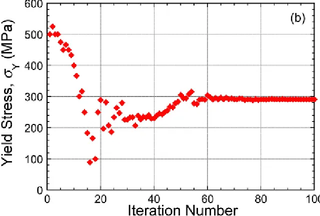
Fig. 1: Nelder–Mead convergence on an optimal (Ludwik–Hollomon) parameter set, targeting a load-displacement plot from indentation of a brass sample, showing the evolution with iteration number of the goodness-of-fit parameter, Sred.
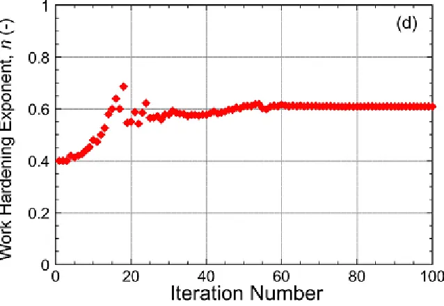
Fig. 3: Nelder–Mead convergence on an optimal (Ludwik–Hollomon) parameter set, targeting a load-displacement plot from indentation of a brass sample, showing the evolution with iteration number of work hardening coefficient.
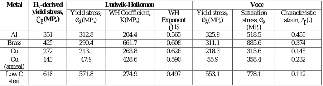
Table 2: Inferred Plasticity Parameter Values
Metal Hv-derived
yield stress, (MPa)
Ludwik-Hollomon Voce
Yield stress, (MPa)
WH Coefficient, K(MPa)
WH Exponent
η(.)
Yield stress, (MPa)
Saturation stress,
(MPa)
Characteristic strain, (.)
Al 351 312.8 204.4 0.565 325.9 518.5 0.455 Brass 425 290.4 661.7 0.608 311.1 885.6 0.374 Cu 272 213.1 263.8 0.626 218.3 315.6 0.145 Cu
(anneal)
143 47.9 428.6 0.590 55.9 358.4 0.232
Low C steel
618 571.8 274.9 0.497 553.1 778.1 0.112
XII. CONCLUSIONS
The following conclusions can be drawn from this work:
(a) The methodology of iterative FEM simulation of the indentation process is basically sound and can in principle be used to infer various mechanical properties. While the present work is focused on plasticity, the approach is also applicable to others, such as creep and superelasticity. It will always be necessary to use a constitutive law of some type, with the objective being to evaluate the parameters in such an equation.
(b) The current work has involved detailed study of computational aspects of how this methodology can be optimized (for plasticity). It is already recognized that yielding and work-hardening characteristics of most (metallic) materials can be well captured by at least one of the two most commonly-used constitutive laws (Ludwik–Hollomon and Voce), both of which incorporate 3 parameter values. Finding the set of these values that best captures the behavior thus requires searching 3-D parameter space for the location where predicted outcomes of an indentation test match the corresponding experimental outcomes most closely. However, the friction coefficient, μ, during indentation is a further
parameter that needs to be included in this optimization. It is shown here that neglect of friction will often introduce a significant error. On the other hand, it appears that, above ∼0.15, the effect of it being changed is small. A value of 0.2 has been used in all of the results presented here.
(c) The prime outcome used in the current work has been the load-displacement plot obtained during testing (with a spherical indenter), although the residual indent shape has also been used. An important deduction is that, in order to obtain outcomes that are reasonably sensitive to the work hardening characteristics, relatively deep indenter penetration
is required. The penetration ratio, δ/R, should be at least ∼25% and preferably ∼40%. The other key issue relating to scale is that the sample volume deformed during the test must be large enough to capture the “bulk” response, which usually means that it must contain a sizeable number of grains (perhaps>∼20). This leads to a requirement for relatively large indenters (∼ mm range) and loads (∼kN range).
(d) Information is also presented about the computational approaches and algorithms. Searching of plasticity parameter space is done on the basis of a goodness-of-fit parameter and the current work has involved minimizing S (the sum of
the squares of the residuals). It is shown that an adaptation of the Nelder–Mead simplex search al- gorithm is efficient
in converging fairly rapidly on the best-fit solution. Computing time requirements will depend on a number of factors,
but the procedure is basically a tractable one, with “answers” often obtainable in a matter of minutes (particularly if a “pre-run” matrix of predicted outcomes is available).
REFERENCES
[1] Dao, M., Chollacoop, N., Van Vliet, K.J., Venkatesh, T.A., Suresh, S., “Computational modeling of the forward and reverse problems in instrumented sharp indentation”. Acta Mater. 49, 3899–3918. 2001.
[2] Bolzon, G., Maier, G., Panico, M., “Material model calibration by indentation, imprint mapping and inverse analysis”. Int. J. Solids Struct. 41 (11-12), 2957–2975. 2004.
[3] Bouzakis, K., Michailidis, N., “Coating elastic-plastic properties determined by means of nanoindentations and FEM-supported evaluation algorithms”. Thin Solid Films 469, 227–232. 2004.
[4] Bouzakis, K., Michailidis, N., “An accurate and fast approach for determining materials stress-strain curves by nanoindentation and its FEM-based simulation”. Mater. Charact. 56, 147–157. 2006.
[5] Pelletier, H., “Predictive model to estimate the stress-strain curves of bulk metals using nanoindentation”. Tribol. Int. 39 (7), 593–606. 2006. [6] Guelorget, B., Francois, M., Liu, C., Lu, J., “Extracting the plastic properties of metal materials from microindentation tests: experimental
comparison of recently published methods”. J. Mater. Res. 22, 1512–1519. 2007.
[7] Heinrich, C., Waas, A.M., Wineman, A.S., “Determination of material properties using nanoindentation and multiple indenter tips”. Int. J. Solids Struct. 46, 364–376. 2009.
[8] Dean, J., Wheeler, J.M., Clyne, T.W., “Use of quasi-static nanoindentation data to obtain stress-strain characteristics for metallic materials”. Acta Mater. 58, 3613–3623. 2010.
[9] Bobzin, K., Bagcivan, N., Theiss, S., Brugnara, R., Perne, J., “Approach to determine stress strain curves by FEM supported nanoindentation”. Materialwiss. Werkstofftech. 44 (6), 571–576. 2013.
[10]Patel, D.K., Kalidindi, S.R., “Correlation of spherical nanoindentation stress-strain curves to simple compression stress-strain curves for elastic-plastic isotropic materials using finite element models”. Acta Mater. 112, 295–302. 2016.
[11]Dean, J., Clyne, T.W., “Extraction of plasticity parameters from a single test using a spherical indenter and FEM modeling”. Mech. Mater. 105, 112–122. 2017.
[12]Isselin, J., Iost, A., Golek, J., Najjar, D., Bigerelle, M., “Assessment of the constitutive law by inverse methodology: Small punch test and hardness”. J. Nucl. Mater. 352 (1-3), 97–106. 2006.
[13]Karthik, V., Visweswaran, P., Bhushan, A., Pawaskar, D.N., Kasiviswanathan, K.V., Jayakumar, T., Raj, B., “Finite element analysis of spherical indentation to study pile-up/sink-in phenomena in steels and experimental validation”. Int. J. Mech. Sci. 54 (1), 74–83. 2012.
[14]Mecking, H., Kocks, U.F., “Kinetics of flow and strain-hardening”. Acta Metall. 29 (11), 1865–1875. 1981.
[15]Estrin, Y., Mecking, H., “A unified phenomenological description of work hardening and creep based on one-parameter models”. Acta Metall. 32 (1), 57–70. 1984.
[16]Sainath, G., Choudhary, B.K., Christopher, J., Samuel, E.I., Mathew, M.D., “Applicability of Voce equation for tensile flow and work hardening behaviour of P92 ferritic steel”. Int. J. Press. Vessels Pip. 132, 1–9. 2015.
[17]Skelton, R.P., Maier, H.J., Christ, H.J., “The Bauschinger effect, masing model and the Ramberg-Osgood relation for cyclic deformation in metals”. Mater. Sci. Eng. a- Struct. Mater. Prop. Microstruct. Process. 238 (2), 377–390. 1997.
[18]Samuel, K.G., Rodriguez, P., “On power-law type relationships and the Ludwigson explanation for the stress-strain behaviour of AISI 316 stainless steel”. J. Mater. Sci. 40 (21), 5727–5731. 2005.
[19]Riley, K.F., Hobson, M.P., Bence, S.J., “Mathematical Methods for Physics and Engineering”. Cambridge University Press. 2006.